ISSN (Online): 2320-9364, ISSN (Print): 2320-9356
www.ijres.org Volume 3 Issue
10ǁ
October. 2015 ǁ PP.06-10
Design and research of CNC platform based on CAN bus
Hui Luo
1, Xiang Yang Du
21
(College of Mechanical Engineering, Shanghai University of Engineering Science, China) 2
(College of Mechanical Engineering, Shanghai University of Engineering Science, China)
Abstract: The conventional CNC systems mostly adopt closed design in the structure and function, so the
product is not compatible with each other Open CNC system based on CAN bus solves this problem.The advancement of CAD and CAM technology based on CAN bus can make CAD / CAM system generate NC code which directly control machine tool to achieve automated production . CAN bus networking communication connect dispersed CNC machine tools,so that you can lower cost to achieve directly digital control with DNC. The design are required to complete a open three-axis CNC platform based on CAN bus. Required to have openness, each CNC system collects real-time data which is uploaded to a central control room, then the host computer produce control instructions after co-synthesis process. In addition, each module has a strong independence NC which can also be used in other systems. In all,the system has reliable, responsive, cheap performance and so on.
Keywords: open NC; CAN bus; CAD/CAM; digital control.
I.
Introduction
Open field bus is critical. Because open CNC system usually requires field bus as an interface between CNC system and servo-drive . Domestic CNC systems are lagging behind foreign manufacturers in field bus standards,and digital servo drive products . Interface between CNC and servo drive is still a "pulse or analog interfaces" standard, which can not meet the communication requirements of high speed and high precision of CNC system. Thus, field bus technology is backward, which severely restrict the development of China's open-software CNC system.
Judging from point of view of the current domestic research on the field bus, field bus protocols and standards suitable for direction of China's national conditions is the introduction of numerical control system based on CAN bus . Importantly, its transfer rate is superior to foreign mature field bus. Application of CAN and PROFIBUS bus, etc., can make up for the absence of hardware in our country. In the shortest possible time,the core technology of the case is to adopt a common electronic devices to break the foreign aspects of field bus technology blockade against our country.
CAN bus ;that is Controller Area Network, is a serial communication network in the support of real-time and distributed control . Because of its outstanding features and high reliability, it is ideal for processing monitoring equipment of interconnection.Except ,its connection is simple, scale, highly cost-effective. CAN 2.0B protocol includes only the data link layer and physical layer, which can customize the application layer protocol,with great flexibility.
room. Design of online communication rate use 250kbps, improving the response speed of the system; while branch distance, less information, can be used by low-rate of 60kbps in long-distance communication .
Rs232
CAN BUS
...
Figure 1. Composition structure of CAN bus and CNC system
II.
The introduction and concept of open tri-axial CNC platform
Open CNC system is the beginning of the developed countries in the 1990s.The new controllers rush computer software and hardware technology, information technology Operation, control technology into numerical control technology. According to the definition of IEEE, Open CNC system: an open system should enable a variety of applications. which can effectively run on different platforms suppliers, and other applications have Systems interoperable and user switching characteristics.
2.1 aspects of hardware architecture
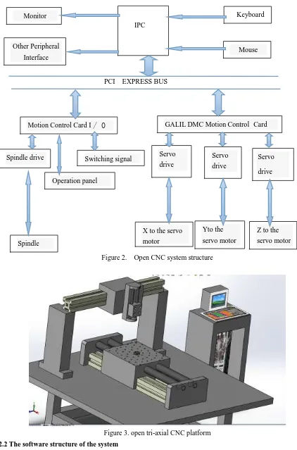
Currently, there are two basic structures for open systems: (1) CNC + PC board:To insert a PC motherboard in a conventional CNC machine.PC board is run in non-real-time control,and CNC main axes is run in movement-based real-time Control. (2) PC + intelligent motion control board: the motion intelligent control
Central control room
IPC Server
Hub
Communication node 1 1
Communication node 2 2
Communication node n
Motion interpol ation 器
Position loop
Encod er
Mot or Commutation
Rotor position Speed
loop
Speed
loop
Speed
loop
Speed
loop
Speed
loop
panel insert Standard PCI slots in the PC for real-time control, and the PC is mainly for Non-real-time control. For many familiar with computer applications, systems manufacturers, often use the second scheme. The structure is shown in Figure 2 and Solidworks Modeling Figure 3.
PCI EXPRESS BUS
Figure 2. Open CNC system structure
Figure 3. open tri-axial CNC platform 2.2 The software structure of the system
Monitor
Other Peripheral Interface
IPC
Keyboard
Spindle drive
Motion Control Card I
/ 0
口
Yto the servo motor
X to the
servo
motor
机
Mouse
GALIL DMC Motion Control Card
Switching signal
Operation panel
Z to the servo motor Spindle
motor
Servo drive
X to the servo motor
X to the
servo motor
Servo drive
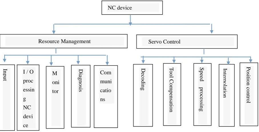
The software structure(figure 4) of the system use a structured pattern front and back, where the foreground program is a real-time interrupt program. to achieve real strong mandate interpolation device communication and control. Background program, whose part of the task is performed by the IPC .It complete whole CNC system by software Windows2000. The operating platform, as well as C programming environment, and modular programming use object-oriented technology, dynamic link library functions to develop and achieve the task through the GT-400 SV motion controller .
Figure 4. Open CNC System Software Framework
III.Achieve data communication based on CAN bus 3.1 PC Command frame format / conversion module of upload data frame
PC Command frame format / conversion module of upload data frame is listed in Table 1.Adopt fixed length format, and include every consultative node information.
Header machine module commands one .... Check End of Frame
1B 3B 8B .... 8B 1B
0XFB Module address Issue command /
upload data
.... CRC 0XFC
Table 1.PC send command frame format
Module address: monitoring node address
Command: Command alarm 、trigger linkage command;
Check: 32-bit CRC.
3.2 The NC node receive / transmit frame format
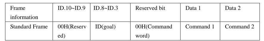
According to the design requirements, the design uses two frame formats: data frame format, the command frame format. Data frames are used to transmit the machine tool offsets, position and speed information about processing parameters.Each module has node real-time acquisition of speed tool path location field, and post-processing temperature of the framing and other information,and send data frames onto the bus. Command frame is a control command issued by the PC , including the alarm command, triggering linkage device command, interpolation algorithm command.
Command is listed in Table 2
NC device 数控装置 数控装置 Resource Management 数控装置 数控装置 Servo Control In p u
t M
oni tor Diag n o sis Com muni catio ns Dec o d in g T o o l Co m p en satio n
Compensation
Compensation
Sp ee d p ro ce ss in g In ter p o latio n Po sitio n co n tr o lFrame information
ID.10~ID.9 ID.8~ID.3 Reserved bit Data 1 Data 2
Standard Frame 00H(Reserv
ed)
ID(goal) 00H(Command
word)
Command 1 Command 2
Table 2. Command frame format
IV. Conclusion
This paper studies the characteristics of CAN bus and structural analysis based on the traditional CNC system, and discusses the open CNC system design.and finally design and implement a field bus based CAN bus on the Open CNC system. The experimental results show that the NC system based on CAN bus to meet the requirements of processing performance . A good next step to prepare the research and introduce group of technology into the numerical control system, which is combined with the characteristics of field bus.Last we will study real-time components technology and its application in Open CNC system .
Reference
[1] Delta Tau.Creatinga Simulated ServoLoopon PMAC(Phanto m Axis).
[2] FREDERICK P,JAMES S A.Open architecture controllers [J].IEEE SP ECTRUM,June,1997.
[3] Y. Koren, C. C. Lo and M. Shpitalni. CNC interpolators: algorithms and analysis. In: Proc. of the ASME Prod EngngyDiv Manuf Sci and Engng. 1993, (64): 83~92.
[4] B. Bahr, X. M. Xiao and K. Krishnan. A real-time scheme of cubic parametric curve interpolations for CNC systems. Computers in Industry. 2001, (45): 309~317 .
[5] Abdel-Ghaf f ar H F, etal . Perf ormance analysis of f ieldbus in process cont rol sys tems [ C] . In: Pr oc. the 2003 American Control Conference, 2003, 1, 591-596.
[6] YASKAWA Document s [ Z] . MECHAT ROLIN-II Application Mod ule Us er' s Manual, 2005. [7] Sungsik Park, Sun-Ho Kim, Hyunbo Cho. Kernel software for efficiently building, configuring, and
distributing an open CNC controller [J]. Institute J Advertise Manufacture Technology. 2006 (27):788-796.