© 2017 IJSRSET | Volume 3 | Issue 2 | Print ISSN: 2395-1990 | Online ISSN : 2394-4099 Themed Section: Engineering and Technology
A Survey on Efficient Rational Sampling Rate Conversion
Algorithms
Priyati Gupta
*1, Amita Verma
2, Ravikant Sharma
3Department of Electronics and Communication Engineering, Green Hills Engineering College, Kumarhatti, Himachal Pradesh, India
ABSTRACT
In many practical applications of digital signal processing sampling rate conversion is a problem. The process of converting a signal from a given rate to a different rate is called Sampling Rate Conversion. Sampling rate conversion process may be based on an integer or a rational factor. In this paper, the process of rational sampling rate conversion is discussed in detail. Along with this, a complete survey of efficient structures for implementing the sampling-rate conversion by a rational factor of L/M is presented.
Keywords: Sampling Rate Conversion, Rational Factor, Finite-impulse-response filter, Linear Phase, Multirate System
I.
INTRODUCTION
In the world today, the demands for digital products with programmability are growing day by day. Because various industries like audio, video, and cellular, rely heavily on digital technology. A best part of digital technology deals with digital signal processing. The digital industry is ever growing, and the development of digitally based products is rising. Most of the common functions performed by almost all DSP chips are FFTs, FIR filters, Interpolator, Decimator. This aspect in engineering has gained increasing interest, because most of the world now turning to wireless technology and its applications to keep businesses and industries connected. Finite impulse response (FIR) digital filters are common DSP functions and are widely used in sampling rate converter implementations. The next section will cover various aspects of both types (FIR and IIR) digital filters.
Sampling rate conversion is a process used to convert sampling rate of a signal from one rate to another. Sampling rates can be increased or decreased according to requirement. Increasing the sampling rate known as interpolation and decreasing the sampling rate is decimation. The multirate techniques are used to convert the given sampling rate to desired sampling rate and are
called multirate system. The basic building blocks of multirate system are interpolators and decimators. This technique is used in many applications like digital audio, communication systems, speech processing, radar systems, antenna systems etc. Sampling rate converter is used in many communication and signal processing applications where two signals or systems having different sampling rates need to be interconnected. For example, in digital audio, the different sampling rates used are 32 KHz for broadcasting, 44.1 kHz for compact disc and 48 kHz for audio tape. In digital video, the sampling rates for composite video signals are 14.318MHz and 17.73MHz for NTSC and PAL respectively. But the sampling rates for digital component of video signals are 11.5 MHz and 6.75 MHz for luminance and color difference signal.
II.
RATIONAL SAMPLING RATE CONVERSION
The need for a non-integer sampling rate conversion may appear when the two systems operating at different sampling rates have to be connected. The change of the sampling frequency by a rational factor L/M, sometimes called the fractional sampling rate alteration or re-sampling, can be achieved by increasing the sampling frequency by L first, and then decreasing by M. Hence, the sampling rate conversion by L/M is achieved by a cascading factor-of-L interpolator and a factor-of-M
decimator.
Here, factors L and M are positive relatively prime integers, i.e. there is no common integer between L and
M. This system can perform SRC for the following cases:
1) Decimation by a factor of M 2) Interpolation by a factor of L 3) SRC by a rational factor of L/M.
SRC by L/M requires performing an interpolation to a sampling rate which is divisible by both L and M. The final output is then achieved by decimating by a factor of M. Appropriate lowpass filtering is required to prevent both imaging and aliasing.
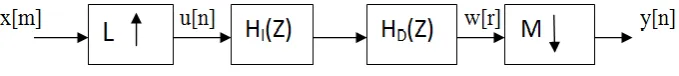
Figure 1: General implementation scheme of sampling rate converter
Figure 2: Efficient implementation of sampling rate converter
In the implementation scheme of Figure 1.10, the original signal {x[n]} is up-sampled-by-L and then filtered by the low pass interpolation filter HI(z). The interpolated signal {w[r]} is filtered with the lowpass anti-aliasing filter HD(z), and then down-sampled-by-M. The sampling rate of the output signal {y[m]} is L/M
times the sampling rate of the original signal {x[n]}. Since the interpolation filter HI(z) and the decimation filter HD(z) operate at the same sampling rate, they can be replaced by the single lowpass filter H(z). The improved diagram is shown in following Figure 1.11.
The relation between the output sampling rate, denoted
by
f
out, and the input sampling rate, denoted byf
in, for the system is given by:out in
L
f
f
M
(1)For sampling rate converter shown in Figure 2, the time domain relations are given as
0, , 2 ,...
[ ]
0
n
x
for n
L
L
u n
L
otherwise
(2)0
[ ] [ ]
N
k k
w n h u n k
(3)[ ]
[
]
y n
w Mn
(4)where
h
k’s are the coefficients of the transfer function
H z . The relationship between u n
and y n
isgiven by the following equation:
0 [ ]
N
k k
Mn k
y n h x
L
(5)Following expression may be considered for
thn
KL
output sample, to represent these0
0
( )
[ ]
N
k k
N
k k
M n KL k
y n KL h x
L
Mn k
h x KM
L
(6)
III. LITERATURE REVIEW
Various techniques have been proposed over the years in order to increase the efficiency and reduce the implementation complexity of the overall system.
Vesa Lehtinen [1] compares four methods for ensuring impulse response symmetry. Comparison of different symmetrization schemes is made. The results indicate that optimization based on the discrete time model often results in better performance than optimization based on the continuous time model and that there are significant performancedifferences between symmetrization schemes. Farrow structure suits well for increasing the sampling rate but performs poorly in decimation.
Robert Bregovic [2] have presented that by designing frequency-response masking approach filters building the FB in such a way that the periodic filters are evaluated at the input sampling rate and the masking filters at the output sampling rate, the design as well as the implementation complexity can be further reduced when compared with the designs obtained by using other existing techniques.
In [3] authors give the alternatives for use of MCM in polyphase decomposed interpolation and decimation FIR filters. It was shown that using the proposed matrix-vector multiplication often is an attractive approach in terms of area, sample rate, and power consumption. To exemplify the area, speed, and power trade-offs for the different approaches we have implemented one interpolation and one decimation filter. The filters are described in VHDL and synthesized using a 0.35 µm standard cell library. Area and sample rates are as reported from the synthesis tool.
Oscar Gustafsson and Hakan Johansson [4] have shown that rational sampling rate conversion based on an FIR filter can be written as a constant matrix multiplication. It was shown that the proposed method in general reduces the arithmetic complexity of the realizations compared with using separate MCM blocks.
Furthermore, it was shown that the number of registers varies between direct form and transposed direct form FIR filter based rational sample rate converters. The structure with the smallest number of registers depends on if the total sample rate is increased or decreased. It is shown that polyphase decomposed FIR filters for rational sampling rate conversion can be viewed as a matrix multiplication and several parallel delay chains. The delay chains are placed before or after the matrix multiplication depending on whether direct form or transposed direct form subfilters are used.
Kyung-Ju Cho [5] represents an efficient structure for sampling rate conversion from 44.1-kHz compact disc to 48-kHz digital audio tape formats. For efficient conversion, we propose a new infinite-impulse response (IIR) fractional delay filter based on Thiran-based IIR allpass filter. It is shown that the proposed method requires less hardware complexity and maintains high quality of signal-to-noise ratio compared with other methods. The proposed SRC shows improved performance compared with Farrowstructure based SRC with less hardware complexity. The application of the proposed algorithm to other SRC cases will be an interesting future work.
Robert Bregovic [6] have proposed a method for implementing a linear-phase prototype filter building a nearly perfect reconstruction cosine-modulated FB in such a way that it enables one to partially utilize the coefficient symmetry, thereby reducing the number of required multiplications in the implementation. The proposed method can be applied for implementing FBs with an arbitrary filter order and number of channels. In this paper, an implementation method that reduces the number of required multiplications when implementing a linear-phase prototype filter of an arbitrary order used for building an NPR cosine-modulated FB has been proposed.
implementation and analysis of the above mentioned architecture. The design has been implemented and tested using ModelSim SE 6.5 and Xilinx ISE Project Navigator, with top level simulations being done in MATLAB. The architecture has been captured using VHDL. Since power consumption is one of the most important parameter in software radio design, the power dissipation measurement of the proposed scheme is compared with an ASIC implementation of two-stage decimation filter in a wireless transceiver. The proposed scheme has been realized onto a Vertex II Pro FPGA using a design methodology which is flexible and allowsthe design and simulation to take place in one step.
Robert Bregovic in [8] has proposed an efficient structure for implementing a linear-phase finite-impulse-response (FIR) filter of an arbitrary order N for the sampling-rate conversion by a rational factor of L/M, where L(M) is the integer up sampling (down sampling) factor to be performed before (after) the actual filter. In this implementation, the coefficient symmetry of the linear-phase filter is exploited as much as possible and the number of delay elements is kept as low as possible while utilizing the following facts. When increasing (decreasing) the sampling rate by a factor of L(M) , only every Lth input sample has a nonzero value (only every Mth output sample has to be evaluated). In this way, the number of required multiplications per output sample is reduced approximately by a factor of two compared with the conventional polyphase implementation.
Yu Huijun [9] has proposed novel design of sampling rate converter based on least square method. To improve the accuracy of signal resampling, a resampling realization method is proposed in this paper. It converts a resampling problem into a time-variable filter designing, so the least square method can be used to obtain the filter coefficients and obtain better accuracy. The experimental results proved that high accuracy signal resampling can be realized with the proposed method. There are two main ways to convert sample rate of a discrete-time system. One is based on polynomial approximation. Although this method has the advantage of high accuracy, the disadvantage is that it has high computation cost. Another is based on multi-rate techniques. This method has the advantage of low computing cost, but the disadvantage is that the filter designing is difficult. A new design of sample-rate converter based on least-square method is proposed to
improve the resampling accuracy. To avoid the ill-conditioning problem which may arise in solving the least-square equations, QR decomposition based on householder transformation is used. This resampling method can obtain higher accuracy and easy be implemented. Further work will improve the algorithm to decrease the computation cost.
Dr S. Ramachanderan and Dr B.S. Nagabushan [10] have proposed a novel architecture for sampling rate converter of the demodulator for processing satellite data communication. The overall receiver algorithm is divided into two parts: one to be implemented on an FPGA and the other on a DSP processor. A new distributed arithmetic based architecture for implementing a Sampling Rate Converter is also proposed. The main advantage of this architecture is that it does not employ any MAC unit, whose operational speed is, generally, a bottleneck for high filter throughput. Instead, it makes extensive use of LUTs and hence is ideally suited for FPGA implementation. The main design goals in this work were to maintain low system complexity and reduce power consumption and chip area requirements. The design of a new distributed arithmetic based architecture for sampling rate converter is presented. The main advantage of this architecture is that it does not employ any MAC unit, whose operational speed is, generally, a bottleneck in filter throughput. It makes extensive use of LUTs and hence, is ideally suited for FPGA implementation.
In [11] a rational sampling rate conversion by L/M is proposed by cascading an L-fold up-sampler and an M-fold down-sampler with a linear phase FIR lowpass filter in the middle. When both L and M have large values, the lowpass filters are required to have an extremely narrow normalized bandwidth and a sharp transition characteristic, causing difficulty in design and implementation. It describes a technique to overcome this difficulty for the case both L and M are composite numbers, giving an multistage converter structure where each stage is consisting of an up-sampler and a down-sampler, both of a small conversion ratios, with a filter having not so sharp normalized transition characteristic in the middle, remarkably reduced total computation complexity.
conversion ratio 2:1 and 4:1. Filter design and implementation are the key points for the converter. First, excluded data and coefficients memories, adopting multiplier-free arithmetic unit (AU) and rounding methods allows its realization in a cell area of only 0.038 mm2 in 0.18 mum technology; next a new timing division multiplexer (TMD) scheme lowers clock working rate to minimum in order to save power; third, a novel memory addressing scheme reduces 20% data memory at least. Experiments show proposed methods could not only saved hardware resources but also reduce power consumption, so it is very suitable for consumer electronics.
In [13], SRC design methods that combine group delay flatness and out-of-band rejection criteria with the minimum mean square error equalization criterion is presented. Data receivers for storage systems normally operate at a fixed sampling rate 1/TS which is asynchronous to the baud rate 1/T. A sampling-rate converter (SRC) serves to convert the incoming signal from the asynchronous to the synchronous clock domain. These receivers also contain an equalizer that serves to suppress intersymbol interference and noise. To limit receiver complexity, equalization burden can be shifted towards the SRC. This possibility is not exploited in any existing SRC. Numerical examples for an idealized optical recording channel validate the design methods.
In [14], a new architecture of a sampling rate converter for high oversampling delta-sigma analog-to-digital converters is presented. The proposed system using a negative feedback technique can greatly reduce the hardware, achieving the rate conversion of the large decimation ratio and the sufficient aliasing suppression with linear phase shift characteristic. A design example is given to demonstrate that the sine function. Compared with a conventional cascaded integrator-comb decimation Alter, a 67% area saving is achieved by the proposed converter.
In [15], sampling rate converters for Software Defined Radio (SDR) is discussed. SDR can implement different wireless standards through software while using a static hardware platform. This can be possible by means of digital signal processing. So, in SDR receiver, received analog Radio Frequency (RF) signal is converted to digital signal by an Analog to Digital Converter (ADC) just after the receiving antenna. Digital signal coming out from ADC has a fixed sample rate. This sample rate
should be converted to another sample rate, according to different wireless standards. This technique is known as Sample Rate Conversion (SRC). This is done for making the digital signal suitable for baseband processing. This paper discusses different techniques to perform SRC and their implementations. This paper also highlights roles of filters in SRC technique and some important constraints to be maintained while designing these filters. Finally it focuses on three types of filters suitable for SRC and mentions some of their advantages and disadvantages.
IV. CONCLUSION
In this paper, a review of rational sampling rate conversion is presented. The design and mathematical analysis of rational sampling rate converters is discussed. Different equations for converter design are discussed. First, basic time domain input and output relations of the converter are outlined. Next, matrix based relations from these time domain relations are extracted for efficient representation and implementation purpose. A brief review of the associated literature is also discussed.
From the literature survey it can be concluded that various approaches of sampling rate converter designed by using various different techniques has presented and unified into an integrated design methodology. Some techniques give good results but complexity increases. In most of the research work two main ways are used to convert sample rate of discrete time system (1) Polynomial approximation (2) Multirate techniques.
V. REFERENCES
[1] Vesa Lehtinen, Djordje Babic and Markku Renfors, “ On impulse Response Symmetry of Farrow Interpolators in Rational Sample Rate Converter”, IEEE Conference on Control, Communication and Signal Processing, pp.693- 696, 2004.
[2] Robert Bregovic, Yong Chng and Tapio Saramaki,“ Frequency Response Masking Based Design of Two-Channel FIR Filterbanks with Rational Sampling Factors and Reduces Implementation Complexity”, IEEE International Conference on Image and Signal Processing and Analysis, pp. 121-126, 2005.
[3] Oscar Gutafsson and Hakan Johanson, “ Implementation of polyphase decomposed FIR filters for interpolation and decimation using multiple constant multiplication techniques”, IEEE Asia Pasific Conference on Circuits and Systems, pp. 924-927, 2006.
[4] Oscar Gutafsson and Hakan Johanson, “Efficient Implementation of FIR Filter Based Rational Sampling Rate Converters Using Constant Matrix Multiplication”, IEEE International Conference on Signals, Systems and Computers, pp. 888-891, 2006.
[5] Kyung-Ju Cho, Ji-Suk Park and Byeong-Kuk Kim, “Design of a Sample-Rate Converter From CD to DAT Using Fractional Delay All pass Filter”, IEEE Transactions on Circuits and Systems, Vol. 54, No.1, pp. 19-23, January 2007. [6] Robert Bregovic, Ya Jun Yu and Ari Viholainen,
“Implementation of Linear-Phase FIR Nearly Perfect Reconstruction Cosine-Modulated Filter banks Utilizing the Coefficient Symmetry”, IEEE Transactions on Circuits and Systems, Vol. 57, No. 1, pp. 139-151, January 2010.
[7] Muhammad ali siddiqui, Nabeel Samad and Shahid Masud, “FPGA based Implementation of Efficient Sample Rate Conversion for Software defined Radios”, IEEE International Conference on computer and Information Technology, pp. 2387-2390, 2010.
[8] Robert Bregovic, Ya JunYu, Tapio Saramaki, “Implementation of Linear-Phase FIR Filters for a Rational Sampling-Rate Conversion Utilizing the Coefficient Symmetry”, IEEE Transactions on Circuits and Systems, Vol. 58, No. 3, pp. 548-561, March 2011.
[9] Yu Huijun, “Design Of A Sample-Rate Converter Based On Least-Square Method”, IEEE International Conference on Computer Science and Information Processing, pp. 332-335, June 2012.
[10] K. R. Nataraj, Dr S. Ramachandran and Dr B. S. Nagabushan, “Design of Architecture for Sampling Rate Converter of demodulator”, IEEE International Conference on Computer and Electrical Engineering, Vol. 2, pp. 427-430, 2009. [11] Takahashi N, Takago D,“Efficient multistage
Implementation of Rational Sampling Rate Converter”, IEEE International Conference on Circuit Theory and Design, pp. 1-4, September 2013.
[12] Haipeng Kuang and Dejiang Wang,“An 8- channel, Area efficient, low power Audio Sampling Rate Converter”, IEEE International Conference on Electronic Measurement and Instruments, pp. 262-265, August 2009.
[13] Raini J,Van Beneden,“Equalizing Sampling Rate converter for Storage Systems”, IEEE International Conference on Acoustics, Speech and signal Processing, Vol. 3, May 2006.
[14] Toshiba Corp and Kawasaki,“An Area Efficient Sampling Rate Converter Using Negative Feedback”, IEEE International Conference on circuits and systems, pp. 1922-1925, May 2008. [15] D. Sinha, A. K. Verma and S. Kumar, "Sample