XML to Annotations Mapping Definition with Patterns
Milan Nosál’ and Jaroslav Porubän
Department of Computers and Informatics, Faculty of Electrical Engineering and Informatics,
Technical University of Košice Letná 9, 042 00, Košice, Slovakia [email protected], [email protected]
Abstract. Currently, the most commonly created formal languages are configura-tion languages. So far source code annotaconfigura-tions and XML are the leading notaconfigura-tions for configuration languages. In this paper, we analyse the correspondence between these two formats. We show that there are typical XML to annotations mapping so-lutions (mapping patterns) that indicate a correspondence between embedded and external metadata formats in general. We argue that mapping patterns facilitate cre-ating configuration tools and we use a case study to show how they can be used to devise a mapping between these two notations.
Keywords:Mapping Patterns, Language Design, Source Code Annotations, Attribu-te-oriented Programming, XML.
1.
Introduction
Usually, a programmer associates the term formal language with compiler/interpreter, maybe parser generators, concrete and abstract syntax, etc.. Therefore when he is asked whether he had already designed a language himself, if he did not work with any of such abstractions and tools, he is going to answer that he did not. However, that would almost definitely be false. Formal languages that are designed and implemented on a daily basis areconfiguration languages. A configuration language is a language that defines what can be customized in a software system. Nowadays each non-trivial system is customizable. User interface style, size and type of font, etc.; even small utilities that programmers implement to help themselves do their everyday work have some options that can be set. Even command line arguments are tiny languages. Such a language may have multiple notations, even graphical, as we argue in our earlier work [11].
This paper concentrates on software system configuration formats. We will use the termsoftware system metadatafor the total sum (everything) of what one can say about any program element, in a machine or human understandable representation. This defini-tion complies with the understanding of software system metadata in Guerra et al. [7].
By the association model (Duval et al. [4]) there are two types of metadata.
– Embedded metadata are metadata that share the source file with the target data. Embedded metadata use in-place binding, they are associated with the target data by their position.
A metadata format is a case of a generic language [1] that can be used to host any formal domain-specific language that conforms to some syntactic restrictions. A generic language is not a language itself; it rather provides a syntactic skeleton that can be used as a basis for the design and implementation of a new language (usually domain specific languages [3]). A generic language restricts the concrete and abstract syntax of the hosted language and in return provides a generic parser that can be used to parse the sentences of the hosted language. The same way, metadata formats provide means to easily define an abstract syntax and a concrete syntax of a language. The configuration module of a system is the implementation of the configuration language semantics. Currently in the industry the most popular embedded and external metadata formats are attribute-oriented programming and XML respectively. Kollár [8] even experiments with an XML format as an intermediate format in language parsing.
Attribute-oriented programming(@OP) is a program level marking technique. This definition shared by many works in the field [10, 15] is a basis for classifying @OP as a form of embedded metadata. A source code annotation (shortly: an annotation) is a concrete mark annotating a program element.
XMLon the other hand is a classic form of external metadata [5, 18, 11]. XML allows structuring metadata and storing them externally to the source code.
The popularity of these formats can be illustrated by many frameworks and systems that use them. For example, Java EE uses both formats in many technologies such as the Java Persistence API (JPA) or Enterprise Java Beans (EJB). The .NET framework extensively uses both XML formats (e.g., in the Enterprise Library) and .NET attributes.
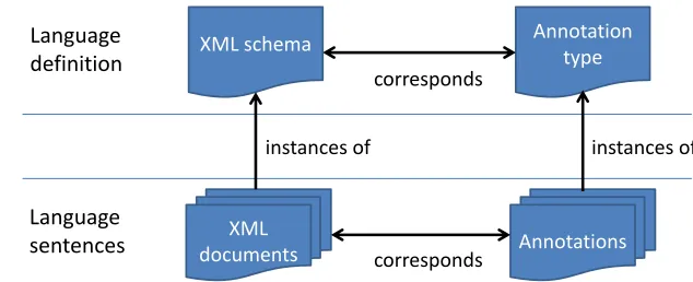
XML and annotations are both generic languages. They both allow "borrowing" their syntax for language design and provide standard parsers (often called processors). Their correspondence in this sense is outlined in Figure 1. The scheme explains that the mapping between them works on two levels – language sentences, and language definitions. An XML document corresponds to annotations where an XML document is a sentence of an XML language and annotations are a sentence of an annotation-based language. On the level of language definition, an annotation-based language is defined using annotation types, which correspond to the XML language definition. In Figure 1, we chose the most popular XML definition language, XML schema.
XML schema Annotation
type
XML
documents Annotations
instances of instances of
corresponds
corresponds
Language
definition
Language
sentences
The similarities between annotations and XML allow for mapping a configuration language to both formats (as many frameworks do). An example is a mapping of an XML element to an annotation and XML subelements and attributes to annotation parameters. In the XML language, a sequence of the same XML elements is a common structure. In annotations, a sequence can be represented by an array.
The two formats do not correspond in all aspects. So far the implementations of source code annotations provide some restrictions that impair full correspondence to XML. In XML, there can be a tree of elements of infinite depth. Current implementations of an-notations do not allow that. Even between implementations there are some discrepancies. For example, .NET attributes allow multiple occurrences of the same annotation types to annotate the same program element. Java annotations do not support that. Therefore, it is sometimes useful to look at annotations and XML as complementing notations and not just as interchangeable.
In our research we have analysed the potential correspondence between these two for-mats. The hypothesis of this research was our assumption thatthere are typical mapping solutions between annotations and XMLthat can be found across multiple frameworks that support configuration through both annotations and XML.
2.
XML to Annotations Mapping
Why would anyone want to map a language in one notation to the other? There are char-acteristics of these notations that make them complement each other. In some situations, annotations are better; sometimes XML documents are advantageous.
2.1. Related Work
Fernandes et al. [5] present a case study that compares three forms of configuration meta-data – annotations, meta-databases and XML. They compare these formats according to three criteria: the ability to change metadata during runtime of a system; the ability to use multiple configurations for the same program elements; and support for the definition of custom metadata. Tilevich et al. [18] compare annotations and XML in few aspects such as programmability, reusability, maintainability, and understandability.
Annotations’ association model and their native support in a language is the reason why Tansey et al. [17] talk about annotations as a tool for more robust and less verbose software system metadata. The XML navigational binding is more fragile during refac-toring and evolution of the program than in-place binding [16, 18]. Annotations’ com-pactness and simplicity is a consequence of native support in a language, that lowers the redundancy of structural information [13]. Since the annotations are a part of a host lan-guage, changes in annotations need recompilation. If runtime changes of configurations are a requirement, external metadata are a viable solution [7, 11].
All these arguments show that the use of both annotations and XML have their sense and meaning. Therefore, we think that there are situations when one language notation is no longer the better and there is a need to map one configuration language to the other. If it is expected that there will be situations in which annotations are more adequate and also situations in which XML is better, then it is useful to support two notations for a config-uration language, one annotation-based and one XML-based. This we consider the main motivation for a mapping definition. An interesting related work that deals with finding mappings between XML and object-oriented notations is a comprehensive discussion of XML to objects mapping by Lämmel et al. [9].
2.2. Mapping Usage Scenarios
Above we have presented a motivation for finding a mapping definition. In this section we want to consider the scenarios that require mapping definition. The mapping definition is needed in the following scenarios:
– Rewriting an existing system from one configuration format to another – a system author decides to change the configuration notation from XML to annotations or vice versa. He/she has to map the old configuration to a new one to make the new config-uration language easily usable by the users of the system.
– Adding a new configuration notation to an existing system– in this situation a system supports XML or annotations but not both. A system author wants to support a new configuration notation in order to gain benefits of supporting multiple configuration formats. Again a mapping definition is needed.
– Building a new system supporting multiple configuration notations– a mapping is needed even when the two configuration notations for the language are designed si-multaneously from scratch. It is similar to adding a notation to an existing system. However, in this situation it may be a little easier since a programmer can adapt one notation (concrete syntax) to the capabilities of the other thus creating two balanced notations. During the addition of a new notation the old one is usually frozen to keep backward compatibility.
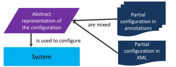
These situations can be abstracted and are summarised in Figure 2. In short, there is a need to define mappings between annotations and XML to define configurations both with XML and annotations. If the case is that configurations are moving from one format to another, then mappings are needed to reuse domain knowledge from the old language.
2.3. XML to @OP Mapping Patterns
System
Partial configuration in
annotations
Partial configuration in
XML Abstract
representation of
the configuration are mixed
is used to configure
Fig. 2.XML and annotation-based configurations
A new version of the tool was built upon a notion of a metamodel. A metamodel de-fines an abstract syntax of a configuration language and its mapping to multiple concrete syntaxes. We designed a metamodel for annotations and XML (we describe it in detail in [11]). It allowed us to define arbitrary mappings between annotations and XML.
However, new experiments showed us that although we could map configuration lan-guages from all chosen industrial frameworks, suddenly even a simple and straightforward mapping required a significant effort (because of the metamodel generality). Even in stan-dard situations a user had to define the mapping in detail. The final effort was comparable with implementing a processor of both formats in adhoc manner. We have realised that if there were typical mapping solutions we could use them to implement a mapping DSL that would significantly reduce mapping definition efforts for most common cases. A DSL would be transformed to a metamodel. Considering the number of frameworks using both annotations and XML as configuration formats we assumed that there should be typical mapping solutions. We took the second prototype and designed a new configuration inter-face to it built upon an annotation-based mapping DSL. A parsed sentence resulted in a metamodel instance that could be modified programatically if there was a need for some specific mapping.
By analysing mappings from industrial systems we discovered multiple typical map-ping solutions that we callXML to @OP mapping patterns (shortly: mapping patterns). A catalogue of discovered patterns is presented in Section 3. Most of the discovered patterns found their place in the prototypes’s configuration interface, some of them were discov-ered later and are to be implemented in the future. These patterns prove our hypothesis about typical mapping solutions. There are three consequences of their discovery.
First,mapping patterns indicate a correspondence between embedded and external metadata. Even with these essentially different format types we can see that most of the languages can interchangeably use annotation-based and XML-based notations.
Second,mapping patterns are beneficial for creating configuration interfacesof soft-ware systems including tools for transformation between different formats. This conse-quence is illustrated in detail by a case study presented in Section 4.
notions of the mapping definition a programmer can just refer to a concrete pattern. This reduces documentation costs since it is easier and faster to just refer to the pattern than to explain how the mapping works for a particular case.
3.
Patterns Catalogue
In this paper, we will focus on mapping definition construction. We will present shortened version of the mapping patterns catalogue where some details and examples are omitted. For a detailed version of the catalogue we refer the reader to [12]. The patterns are cate-gorized into structural mapping patterns and program element binding patterns.
The following describes a pattern’s description elements.
– TheMotivationpresents a problem context in which the pattern’s solution is suitable. – TheProblemstates the question to which a pattern provides an answer.
– Forceslists conflicting forces that the pattern should help balance. – TheSolutiondescribes the mapping pattern.
– Consequenceslist the possible positive/negative consequences of pattern application. – Known Useslist selected known uses of the described pattern.
3.1. Structural Mapping Patterns
The first group of patterns are structural patterns. They aim to show the fundamental map-pings between XML and annotations. They do not deal with the relationship of a configu-ration to the program structure, they deal only with the structural mappings between XML and annotations.
An example when these patterns can be applied without target element binding pat-terns are global configurations that are not configurations of some program element but of a system as a whole. In case of configurations through annotations this means that the binding of configuration annotations to program elements does not have to be significant. Probably the best case would be if they could just annotate a system as a whole. However, currently the source code annotations do not support annotating a whole system. In Java, there are package annotations that are usually used for this purpose. In the .NET frame-work, there is an option to annotate assemblies. Another solution may be annotating an arbitrary class or a class that is significant for configuration.
Direct Mapping Pattern
Motivation.The first and basic problem when mapping a language from XML to anno-tations (or vice versa) is the question of how to represent language constructs from one language in another. For example, if there is an annotation-based configuration language and the new language is supposed to be built on XML, there has to be a simple and direct way to match constructs from one language to another to have a starting point.
Problem.What is the most straightforward way to map annotations’ constructs to XML and vice versa?
Forces.
– An annotation-based and an XML-based language need to be able to represent the same configuration information.
Solution.The most common and straightforward way is to use the Direct Mapping pat-tern. By default, the Direct Mapping pattern proposes to map annotation types to XML element types with the same name. Annotation type parameters are mapped to element types with the same name, too. An annotation is then mapped to an XML element. From the point of view of XML an XML element is by default mapped to an annotation that has its simple name identical to the corresponding XML element’s name. XML attributes are mapped to annotation type parameters of the same name.
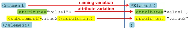
There are pattern variations concerning the name mapping and XML attribute/element mapping choice. Naming pattern variation allows different names (in this context we can speak of keywords) for mapped constructs in both languages. It allows keeping nam-ing conventions in both formats, identifiers startnam-ing with uppercase for Java annotation types and identifiers starting with lowercase in XML. For some language constructs in annotation-based languages it might be interesting to use XML attributes instead of el-ements. This concerns only marker annotations (see [19]) and annotation members that have as return type a primitive, string or a class (if its canonical name is sufficient in XML). For example, arrays are excluded since XML attributes are of simple type and there cannot be more than one attribute with the same name. The scheme of the Direct Mapping pattern with both variations is shown in Figure 3.
@Element(
attribute="value1", subelement="value2" )
<element
attribute="value1">
<subelement>value2</subelement> </element>
naming variation attribute variation
Fig. 3.Direct Mapping pattern scheme
Consequences.
[+] Simple XML structures can be mapped to annotations and vice versa. [+] Naming parameterization allows different names in annotations and in XML. [+] In some cases element/attribute choice parameterization allows more convenient XML notation, because XML attributes are less verbose than XML elements.
[–] More complex mappings cannot be realised with this pattern.
Known Uses.
– JAX-WS’s mapping of theserviceNameparameter of the@WebService anno-tation towsdl:serviceelement of WSDL language.
– JSF’s maps the@ManagedBeanannotation tomanaged-beanelement. – JPA also uses this pattern, see the case study in Section 4.1.
Nested Annotations Pattern
Motivation.Another structural problem of mapping is handling the XML tree structure in annotations. The tree structure of XML is usually significant.
Forces.
– XML allows to structure configuration information to trees of element nodes and their attributes.
– The meaning of the tree structure is significant and therefore it has to be preserved in some form in annotations.
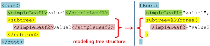
Solution.The Nested Annotations pattern nests annotations in order to model a tree struc-ture. The root of the tree in XML is modelled by an annotation type and its direct descen-dants (in XPath the children axis of the XML element) are modelled by the parameters of the annotation type. This pattern can be applied recursively. If one of the descendants has children itself, its type will be an annotation type, too. The children of the descendant will become annotation type parameters. Figure 4 shows a scheme of the Nested Annotations pattern. However, the Nested Annotations pattern is still rather limited as it cannot be used in several situations, like in .NET or for modelling cyclic XML structures.
@Root(
simpleLeaf1="value1", subtree=@Subtree( simpleLeaf2="value2" )
) <root>
<simpleLeaf1>value1</simpleLeaf1> <subtree>
<simpleLeaf2>value2</simpleLeaf2> </subtree>
</root> modeling tree structure
Fig. 4.Nested Annotations pattern scheme
Consequences.
[+] XML tree structures can be mapped to annotations.
[–] Currently available annotations’ implementations do not support cyclic nesting. If the XML language has an element that can have itself as a descendant, this pattern cannot be used. XML allows modelling arbitrary trees, e.g., there can be anodeXML element with child elements of the same type. The same is not allowed in annotations.
[–] The sequence of annotation members is not preserved during the compilation; there-fore if the order is significant, this approach will fail. The only way of preserving the order of the elements in annotations is the use of an array as an annotation parameter type. [–] In programming languages that do not support annotation nesting at all (e.g., .NET) the pattern is not applicable.
[–] All nested annotations inherit the target program element from the root annotation. Therefore, the modelled XML tree has to apply to the same target program element.
Known Uses.
– In JPA there is a@Tableannotation with the parameteruniqueConstraints
that is of the type array of@Uniqueannotations. The@Tableis mapped totable
element anduniqueConstraints are mapped to its unique-constraint
subelement with its own children.
map-ped to themessage-drivenelement and the parameteractivationConfig
to theactivation-config-propertyelement.
– The@WebFilterannotation in the Java Servlets technology uses the Nested Anno-tations pattern. Its parameterinitParamsis an array of@WebInitParam anno-tations. The@WebFilteris mapped to thefilterXML element and the config-uration branch represented by theinitParamsannotation parameter is mapped to an XML subtreeinit-param(or in fact multiple subtrees, since theinitParams
parameter is an array).
Enumeration Pattern
Motivation.Sometimes there is a piece of configuration information represented by a set of mutually exclusive marker annotations. Designing an XML language with "marker" XML elements might seem a little too verbose and it increases the complexity of XML instance documents.
Problem.How to elegantly map a set of mutually exclusive marker annotations to XML?
Forces.
– There is a configuration property that is in annotation represented by a set of mutually exclusive marker annotations.
– The Direct Mapping pattern makes the XML language too complex.
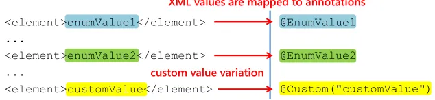
Solution.The Enumeration pattern proposes to map a set of mutually exclusive marker annotations to XML element values instead of elements themselves. Each of the marker annotations is mapped to an enumeration value.
This pattern can be extended by allowing more occurrences of the enumeration ele-ment tu support also marker annotations that are not mutually exclusive. Custom value parameterization allows to have one annotation with a parameter (such as in case of JSF managed beans) that is mapped to XML element’s values that are not part of the enumer-ation. In Figure 5 there is a scheme of the Enumeration pattern including also a custom value parameterization.
@EnumValue1
@EnumValue2
@Custom("customValue") <element>enumValue1</element>
...
<element>enumValue2</element> ...
<element>customValue</element>
XML values are mapped to annotations
custom value variation
Fig. 5.Enumeration pattern scheme
Consequences.
[+] The XML language can be more compact and comprehensible.
Known Uses.
– The JSF technology uses this pattern to specify the scope of their managed beans. The JSF scoping annotations (e.g.,@RequestScoped) are mapped to a single XML el-ement – themanaged-bean-scopeelement. The@CustomScopedannotation has a parameter that is mapped to themanaged-bean-scopevalue thus imple-menting custom value pattern parameterization.
– EJB use@Stateless,@Statefuland@Singletonannotations to configure session beans. These three annotations are mapped to thesession-typeXML element’s value in the XML deployment descriptor.
Wrapper Pattern
Motivation. In some situations there may be an implicit grouping property in annota-tions that has to be mapped to XML. An example may be a grouping of some pieces of configuration information according to their bound target elements. In annotations, this structuring is implicit according to their usage, for example they annotate the members of the same class.
Problem.How to represent grouping in XML that is based on some implicit property of annotations?
Forces.
– Annotations use some implicit grouping property that does not have an appropriate language construct that could be mapped to XML.
– Grouping is closed on branches and depth – grouping is defined strictly on one branch in a tree and it groups only constructs on the same level in the tree.
Solution.The Wrapper pattern proposes to map implicit groupings from annotations to so called wrapper XML elements. A Wrapper XML element is an element that groups together elements according to some property. A Wrapper XML element does not have its counterpart in annotations, at least not an explicit language construct like an annotation or an annotation parameter. The Wrapper pattern is usually just a notation enhancement. For example, binding to the members of the same class can be recovered from target program element specifications. The Wrapper pattern structurally enhances the notation in XML, for example, for design reasons. To increase comprehensibility we recommend using a naming convention for the Wrapper XML element so that its name will refer to the common property of wrapped information. For example, when annotations annotate the fields of the same class the Wrapper XML element should be namedfields. Another viable option is to use a domain-specific term. In the same example if the class represents an entity and its fields the entity attributes thenattributesWrapper element would be good, too.
Consequences.
[+] XML can model some implicit properties of the annotations or the target program. [+] The Wrapper pattern may increase the readability of the XML configuration language. [+] Wrapper pattern is used to overcome the problem of annotating the program element with more annotations of the same type (Vectorial Annotation idiom from [6]).
public class SomeClass { @Element
private String field1; @Element
private String field2; @AnotherElement
private String field3; ...
<wrapper>
<element field="field1"/>
<element field="field2"/>
<anotherElement field="field3"/>
</wrapper>
no explicit equivalent in @OP
X
X
Fig. 6.Wrapper pattern scheme
Known Uses.
– JPA uses theattributesWrapper XML element, for details see the case study in Section 4.1.
– JPA also uses the@NamedQueriesvectorial annotation that is a Wrapper for an ar-ray of@NamedQueryannotations. In XML, the@NamedQueriesannotation does not have an equivalent, thenamed-queryXML elements (that are mapped to the
@NamedQueryannotations) are directly situated in the rootentity-mappings
element.
– The@MessageDrivenannotation from EJB has a parameter that is of typearray of
@ActivationConfigProperty. The XMLactivation-config wrapper element wrapsactivation-config-propertyelements representing
@ActivationConfigPropertyannotations.
Distribution Pattern
Motivation.Sometimes the same configuration information is supposed to be distributed in one configuration language differently than in another. There may be some configu-ration information that in XML, due to design reasons, is separated from its logical tree structure, but it still has to be somehow associated together as a logic unit. An example may be dealing with so called Fat Annotation annotations’ bad smell (Correia et al. in [2]). While an XML element with many children elements might be good, overparameterized annotations might increase code complexity and reduce code readability.
Problem.How to handle different distributions of configuration information in XML and annotations?
Forces.
– Due to design decisions one or more constructs in the first language are mapped to one or more constructs in the second language, while the mapping is not straightforward. – Distributed constructs need to be tied together to form a logical unit.
– Logical units in both languages need unambiguous mapping to their counterparts.
there is a simple scheme of the distribution pattern, where the information from one an-notation is distributed to two elements in XML. However, the Distribution pattern signif-icantly increases the complexity of the mapping and therefore its use should be carefully considered.
@Annotation( id="identifier", info1="value1", info2="value2" )
public class SomeClass { ...
<element>
<id>identifier</id> <info1>value1</info1> </element>
...
<anotherElement> <id>identifier</id> <info2>value2</info2> </anotherElement>
bound with identifier
Fig. 7.Distribution pattern scheme
Consequences.
[+] More complicated tree structures of configuration languages are possible that do not have to strictly follow each other.
[–] The pattern may require adding an identifier to the pre-existing configuration notation in the scenario of converting from one configuration language to the other.
[–] Differences in the notations increase the complexity and readability of the mapping.
Known Uses.
– The Java Servlets technology uses the@WebServletannotation to annotate a serv-let implementation and through parameters specify a servserv-let’s name and its URL map-pings. XML configurations distribute these pieces of information to theservlet
XML element, that specifies the servlet and binds it to its implementation, and to possibly multipleservlet-mappingXML elements (one for each URL mapping in annotations). Theservlet-mappingand theservletelements are tied to-gether by the servlet’s name, which is the servlet’s identifier.
– Java Servlets use the same approach with the@WebFilterannotations.
3.2. Program Element Binding Patterns
Target Pattern
Motivation. @OP is a form of embedded metadata. Annotations are always bound to program elements. XML elements that carry the configuration information have to be bound to program elements, too.
Problem.How to bind XML elements and/or attributes to program elements?
Forces.
– XML does not have in-place program element binding as embedded metadata do. – XML elements/attributes have to be bound to the same program elements as their
corresponding annotation constructs.
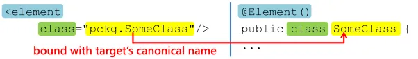
Solution.The Target pattern proposes to use a special dedicated XML element or attribute to set a target program element for an XML element. An attribute is preferred to make the notation more compact. The name of the dedicated element/attribute has to be unique in a given context for the node to be distinguishable from other nodes used to carry configura-tion informaconfigura-tion. By default the generic name is used (e.g., "class" for binding elements to class definitions). By means of parameterization a special name can be used, that may suit better for the language. Another reason may be preventing name clashes if the lan-guage already defines a node with the same name that is used to represent configuration information. To make the notation shorter, the target program element is inherited in XML branches, analogously to XML namespaces. Thus, by default a whole branch is bound to the same target program element. Figure 8 shows a scheme of the Target pattern.
@Element()
public class SomeClass { ...
<element
class="pckg.SomeClass"/>
bound with target’s canonical name
Fig. 8.Target pattern scheme
A more structured approach can be used as well. The reference can be structured to multiple XML elements/attributes. For example, a canonical name of the class member can be split to the class name and to the simple name of the member. This can be useful when there is a need to use both of these pieces of configuration information. Then the canonical name does not have to be parsed every time the configuration is read. EJB uses this approach in the example mentioned in Known Uses.
Consequences.
[+] XML elements and attributes can be bound to target program elements.
[–] Navigational binding using the names of target program elements is error-prone due to the absence of code refactoring that would take into account the composition of languages. If a programmer changes the name of a method, thanks to in-place binding, annotations will still be valid while XML will need manual refactoring or a respective tool.
Known Uses.
– The JSF technology uses the Target pattern in themanaged-beanXML element to bind it to the program element, to which its counterpart – the@ManagedBean an-notation, is bound. Themanaged-beanelement has themanaged-bean-class
– Servlets have the XMLservletelement with a childservlet-classelement that binds the servlet to its implementation.
– EJB use theresource-refXML element as an equivalent to the@Resource an-notation. Theresource-refelement is bound to its target program element by the
injection-targetXML element, that has two descendants,injection-tar get-classspecifying the target class, andinjection-target-name identi-fies the actual field to be injected (a structured variation of the pattern).
– JPA also uses this pattern, see the case study in Subsection 4.1.
Parent Pattern
Motivation.Sometimes the Nested Annotations pattern is not suitable for modelling the XML tree. In case of the object-relational mapping tools such as JPA the columns of the database table belong to the table. In XML, this is modelled by putting the column element into the table element. Using the Nested Annotations pattern this would be mod-elled by a single annotation@Tablewith a member that would have the type ofarray of @Columnannotations. But these annotations have a different target program element than the@Tablethat annotates the class. They should annotate the class members. Ac-cording to the Target element pattern, in the Nested Annotations pattern, the parameters of annotations are bound to the same target program element as the annotations themselves.
Problem.How to model an XML tree structure in annotations when the descendants of the branch root element belong to a different target program element than the branch root?
Forces.
– XML allows to group elements by their meaning and to create trees of element nodes. – The meaning of the structure is significant and therefore it has to be preserved in some
form in annotations.
– Some of the XML elements or attributes in the branch belong to different target pro-gram elements than the branch root.
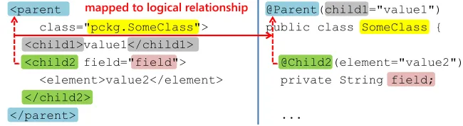
Solution. The Parent pattern proposes to define parent-child relationships between an-notation types. This relationship defines two roles, parent and its children. Parent-child relationships can be used to define logical tree structures consisting of annotations. Meta-data carried by annotations in the children role are considered to be on the same level as the parent’s parameters.
relationship will stay explicit in annotations too (annotation as parent and its parameter as child). That makes the annotation-based notation more comprehensible.
@Parent(child1="value1") public class SomeClass {
@Child2(element="value2") private String field;
... <parent
class="pckg.SomeClass"> <child1>value1</child1> <child2 field="field"> <element>value2</element> </child2>
</parent>
mapped to logical relationship
Fig. 9.A scheme of the Parent pattern on the descendant-axis (using relative naming)
In the XML tree the new target program element of some of the descendants can be specified both using its absolute name – the full canonical name of the program element; or using a relative name, specifying the identifier relative to the current target element context1.
This pattern allows to override the inherited target program element in XML by ex-plicitly specifying a new target program element. Annotations have to define a logical relationship to preserve the desired structure from XML and to still properly annotate different target program elements.
Consequences.
[+] XML tree structures can be mapped to annotations.
[+] Different target program elements of the configuration information in the tree are preserved in the annotation’s concrete syntax.
[+] In programming languages that do not support annotation nesting this pattern can substitute the nested annotations pattern (using the self axis).
[–] Using unnatural or complicated matching algorithms may decrease annotation-based language’s understandability and usability. We believe the direct descendant axis can be understood most easily.
Known Uses.
– JSF uses the Parent pattern on the self axis with annotations@ManagedBeanand scope annotations, such as@RequestScopedor@SessionScoped. Scope an-notations are logical descendants of the@ManagedBeanannotation.
– JPA also uses this pattern, see the case study in Section 4.1.
Mixing Point Pattern
Motivation.If the system supports both XML and annotations, there has to be a mech-anism to recognize whether some configuration information is in both annotations and XML or just in one of the formats. The common situation may be using an annotation-based configuration language to define a default configuration and an XML-annotation-based
lan-1
guage to override the default configuration. In such a situation processing only one con-figuration format based on users choice is not sufficient, finer granularity in mixing is required than just on the root construct level. The languages should not only be substi-tutable but rather be able to complement each other.
Problem.How to provide finer granularity for duplicity checking in XML and annotation-based configuration languages?
Forces.
– The annotation-based and XML-based configuration languages can both be used to define the configuration.
– Some pieces of the configuration are duplicated in either XML and annotations. – Both the XML and annotation-based configurations are incomplete, a complete
con-figuration is a combination of both.
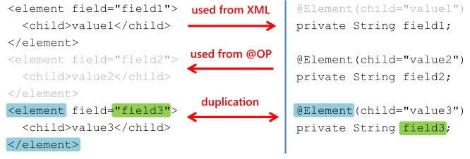
Solution.The Mixing Point pattern proposes to define so called mixing points in a tree structure of the languages. A mixing point node has to be unambiguously identified, e.g., by its name and target program element. These two properties are represented in both formats using the Direct Mapping and the Target pattern. When a node in a tree is a mixing point, the checks for duplication on its level must be performed in both annotation and XML-based trees and the configuration information is mixed from both sources. If a node is not a mixing point, no mixing is performed and the information is taken from the language with higher priority. The Mixing Point pattern varies in the priority parameter. In case of duplication the configuration in notation with highest priority is used. A root node is by default a mixing point. Figure 10 shows the scheme of the pattern.
@Element(child="value1") private String field1;
@Element(child="value2") private String field2;
@Element(child="value3") private String field3; <element field="field1">
<child>value1</child> </element>
<element field="field2"> <child>value2</child> </element>
<element field="field3"> <child>value3</child> </element>
duplication used from @OP
used from XML
Fig. 10.Mixing Point pattern scheme
Consequences.
[+] A finer granularity of combining two partial configurations in XML and annotations. [–] Sometimes even this granularity is too coarse-grained. Components of array annota-tion members share the same name and target element. To combine two arrays without duplicates, a different duplication detection approach must be used (e.g., based on values).
Known Uses.
– Hibernate (JPA compliant ORM framework) supports mixing, too. However, as mix-ing points there are classes and not fields. It is possible to configure one class through annotations and one through XML, but not to configure one class by mixing both formats. The annotations have higher priority in the Hibernate framework.
4.
JPA Configuration Case Study
In this section we will look closer at how mapping patterns presented in the catalogue work together and how they can be used to efficiently define a mapping between anno-tations and XML. Instead of designing a new configuration language we decided to take an existing technology and study the mapping of its configuration notations. We chose the Java Persistence API (JPA) that is an object-relational mapping specification for Java. It uses a configuration language to specify mappings between entities’ representations in the code and their representations in a relational database.
In Table 1 there is a short summary of the patterns. It can be used for better orientation in choosing the appropriate patterns according to the problem that needs to be solved.
Name Problem
Structural Direct Mapping How to map XML to annotations to keep the map-ping straightforward?
Nested Annotations How to preserve the XML tree structure in annotation-based languages?
Enumeration How to reduce the effort of mapping a set of mutu-ally exclusive marker annotations to XML? Wrapper How to represent grouping in XML that is based on
an implicit property of annotations?
Distribution How to handle a different distribution of configura-tion informaconfigura-tion in XML and annotaconfigura-tions?
Element Binding Target How to bind XML elements to program elements? Parent How to model the XML tree structure with multiple
target elements in annotation-based language? Mixing Point How to provide finer granularity for mixing XML
and annotations?
Table 1.Summary table of patterns
4.1. The JPA Configuration Language
Source 1.A simplePersonentity class
public class Person { private int id;
private String lastName;
... }
This entity class will be mapped to a table namedTABLEPERSON in a relational database. The table will have columns corresponding to the fields of thePersonclass. The correct JPA object-relational mapping using XML and annotations is shown in Source 2 (there may be more basic attributes).
Source 2.Correct equivalent JPA mappings of the Person entity using XML and @OP
<entity class="Person" name="Person">|@Entity(name = "Person")
<table name="TABLEPERSON"/> |@Table(name = "TABLEPERSON") |public class Person {
<attributes> |
<id name="id"> | @Id
<column name="ID"/> | @Column(name = "ID")
</id> | private int id;
|
<basic name="lastName"> | @Column(name = "LASTNAME") <column name="LASTNAME"/> | private String lastName;
</basic> |
</attributes> |...
</entity> |}
4.2. Patterns Application
We will devise an annotation-based notation for an existing XML notation. This transition has become more common in practice after the introduction of annotations on the Java platform since until then the most favourite configuration notation was XML. So in this point we assume that the XML notation shown in Source 2 already exists.
We will start with the most straightforward mapping.Which pattern uses straight-forward mapping?According to Table 1 it is the Direct Mapping pattern. In this case it means that every XML element would be mapped to an annotation, while its subele-ments and attributes would be mapped to parameters of the corresponding annotation. To keep the Java conventions of upper camel case notation for annotation types’ names (e.g.,
Direct Mapping
Nested Annotations
@Entity(name="Person", class="Person", table=@Table(
name="TABLEPERSON"), attributes=@Attributes(
id=@Id( name="id",
column=@Column(name="ID") )
basic={ @Basic(
name="lastName", column=@Column(
name="LASTNAME") )
} ) ) <entity name="Person"
class="Person"> <table
name="TABLEPERSON"/> <attributes>
<id
name="id">
<column name="ID"/> </id>
<basic
name="lastName"> <column
name="LASTNAME"/> </basic>
</attributes> </entity>
array for multiple elements of the same type
Fig. 11.First mapping version with the Direct Mapping and Nested Annotations patterns
The most significant deficiency of the annotation-based notation in figure 11 is that we do not use the natural relation between annotations and program elements. An annotation has to annotate a program element, thus indicating a close relation between the metadata in annotations and the program elements. As a result of using the Direct Mapping pattern there are still annotation parameters referring to program elements.The problem here is to naturally represent the binding of annotations to program elements.So the next step is using the Target pattern and removing the explicit links to the source code (highlighted in blue in Figure 12). In our example we can remove theclassparameter of the@Entity
and express this relation by annotating the proper entity class.
The same way we would like to remove links from@Idand@Basicthat navigate to class fields.Here the problem is to model an XML tree that has multiple target pro-gram elements– a candidate for the Parent pattern. The@Entityannotation will have the parent role and the@Idand@Basicannotations will be its children. It is easy to determine an axis on which the relationship will be defined. Because we need to move the child annotations to fields of the entity class, the pattern will be on the descendant axis of the program element tree. In practice this means that@Idand@Basicannotations can only annotate the fields of a class that is annotated by a parent@Entityannotation. The children are highlighted in green in Figure 12.
a consequence, we can omit theattributesparameter from the@Entityannotation (highlighted in red in Figure 12).
Target
Wrapper
Parent
@Entity(
name="Person",
table=@Table(name="TABLEPERSON")) class Person {
@Id(
column=@Column(name="ID")) int id;
@Basic(
column=@Column(
name="LASTNAME")) String lastName;
... } @Entity(class="Person",
name="Person",
table=@Table(name="TABLEPERSON"), attributes=@Attributes(
id=@Id( name="id",
column=@Column(name="ID"))
basic={
@Basic( name="lastName", column=@Column(
name="LASTNAME")) }
) )
Fig. 12.Second mapping version with the Target, Parent and Wrapper patterns
We were able to significantly reduce redundancy and fragility by using the Target pattern. Using links to code may cause inconsistencies in case of changing the code. Now relationships are expressed by annotating proper program elements.
We can make this notation even shorter and more concise by using the Parent pattern on the self-axis. For example, considering the@Idand the@Columnannotations if the
@Columnwas a child on the self-axis the notation would become shorter by removing the need of using the parameter assigment"column=". This makes the notation shorter and does not impair comprehension since the information that the fieldidis a column is not bound to the information that it is an identifier. Anidfield is an identifierandit is a column (not an identifier andthereforea column). Therefore, the@Idand the@Column
may be both used as two distinct annotations. The same can be done with the@Entity
and the@Tableannotations and with the@Basicand the@Columnannotations. After applying the Self-axis Parent pattern variation the mapping will look like in Figure 13.
The reader can notice that now the notation is shorter but still readable and com-prehensible. This notation is a valid JPA configuration. It differs from the example from Section 4 because there were no@Basicannotations. There the authors of the JPA spec-ification used the default value technique. By default every column attribute of an entity class is considered to be basic if not specified otherwise.@Basicannotations are optional unless some of their attributes differs from default (then they need be stated explicitly).
4.3. Summary
@Entity(name="Person",
table=@Table(name="TABLEPERSON")) class Person {
@Id(
column=@Column(name="ID")) int id;
@Basic(
column=@Column(name="LASTNAME")) String lastName;
... }
@Entity(name="Person") @Table(name="TABLEPERSON") class Person {
@Id
@Column(name="ID") int id;
@Basic
@Column(name="LASTNAME") String lastName;
... } Self-axis Parent
Fig. 13.Final mapping after the Self-axis Parent pattern variation
the Target pattern for binding the configuration information to the source code. These three problems are always present when a programmer defines mapping between XML and annotations. There is always the need to define at least this basic mapping, to map the tree structure of the XML to annotations and to bind the configuration information to the source code. Pattern variations are common, too. Especially, naming and attribute/element variations of the Direct mapping pattern to keep metadata format naming conventions. In case of the Parent pattern, most common are its variations on descendant and self axis.
5.
Conclusion
We analysed the correspondence between XML and annotations and we have presented the discovered XML to annotations mapping patterns that provide a proof of this corre-spondence. The correspondence between these embedded and external format representa-tives is a basis for our future research in which we want to analyse the nature of embedded and external metadata formats.
Discovered mapping patterns can be used to facilitate configuration language devel-opment. Therefore, recognition and formalization of mapping patterns from practice is a contribution to the field of configuration languages. For the complete pattern catalogue we refer to [12].
We presented a case study of constructing a mapping between XML and annotations for a JPA configuration language. The case study provides an insight on how mapping patterns can be used to devise a concise mapping from existing an XML notation to anno-tations. It also indicates which mapping patterns are most common in mapping definitions.
Acknowledgments.This work was supported by VEGA Grant No. 1/0305/11 Co-evolution of the Artifacts Written in Domain-specific Languages Driven by Language Evolution.
References
2. Correia, D.A.A., Guerra, E.M., Silveira, F.F., Fernandes, C.T.: Quality Improvement in Anno-tated Code. CLEI Electron. J. 13(2) (2010)
3. Demirkol, S., Challenger, M., Getir, S., Kosar, T., Kardas, G., Mernik, M.: A DSL for the Development of Software Agents working within a Semantic Web Environment. Computer Science and Information Systems 10(4), 1525–1556 (2013)
4. Duval, E., Hodgins, W., Sutton, S.A., Weibel, S.: Metadata Principles and Practicalities. D-Lib Magazine 8(4) (2002)
5. Fernandes, C., Ribeiro, D., Guerra, E., Nakao, E.: XML, Annotations and Database: a Compar-ative Study of Metadata Definition Strategies for Frameworks. In: Proceedings of XATA 2010: XML, Associated Technologies and Applications. pp. 115–126. XATA 2010 (2010)
6. Guerra, E., Cardoso, M., Silva, J., Fernandes, C.: Idioms for Code Annotations in the Java Language. In: Proceedings of the 17th Latin-American Conference on Pattern Languages of Programs. pp. 1–14. SugarLoafPLoP (2010)
7. Guerra, E., Fernandes, C., Silveira, F.F.: Architectural Patterns for Metadata-based Frameworks Usage. In: Proceedings of the 17th Conference on Pattern Languages of Programs. pp. 1–14. PLoP2010 (2010)
8. Kollár, J.: From XSL Transformation to Automated Software Evolution. Journal of Computer Science and Control Systems 6(1), 52–57 (2013)
9. Lämmel, R., Meijer, E.: Revealing the X/O impedance mismatch: changing lead into gold. In: Proceedings of the 2006 international conference on Datatype-generic programming. pp. 285–367. SSDGP’06, Springer-Verlag, Berlin, Heidelberg (2007)
10. Noguera, C., Pawlak, R.: AVal: an extensible attribute-oriented programming validator for Java: Research Articles. J. Softw. Maint. Evol. 19(4), 253–275 (Jul 2007)
11. Nosál’, M., Porubän, J.: Supporting multiple configuration sources using abstraction. Central European Journal of Computer Science 2(3), 283–299 (Oct 2012)
12. Nosál’, M., Porubän, J.: XML to Annotations Mapping Patterns. In: Leal, J.P., Rocha, R., Simões, A. (eds.) 2nd Symposium on Languages, Applications and Technologies. OpenAccess Series in Informatics (OASIcs), vol. 29, pp. 97–113 (2013)
13. Pawlak, R.: Spoon: Compile-time Annotation Processing for Middleware. IEEE Distributed Systems Online 7(11), 1– (Nov 2006)
14. Porubän, J., Nosál, M.: Leveraging Program Comprehension with Concern-oriented Source Code Projections. In: Pereira, M.J.V., Leal, J.P., Simões, A. (eds.) 3rd Symposium on Lan-guages, Applications and Technologies. OpenAccess Series in Informatics (OASIcs), vol. 38, pp. 35–50 (2014)
15. Rouvoy, R., Merle, P.: Leveraging Component-Oriented Programming with Attribute-Oriented Programming. In: Proceedings of the 11th International ECOOP Workshop on Component-Oriented Programming. WCOP’06, Karlsruhe University (Jul 2006)
16. Song, M., Tilevich, E.: Metadata invariants: checking and inferring metadata coding conven-tions. In: Proceedings of the 2012 International Conference on Software Engineering. pp. 694– 704. ICSE 2012, IEEE Press, Piscataway, NJ, USA (2012)
17. Tansey, W., Tilevich, E.: Annotation refactoring: inferring upgrade transformations for legacy applications. SIGPLAN Not. 43(10), 295–312 (Oct 2008)
18. Tilevich, E., Song, M.: Reusable enterprise metadata with pattern-based structural expressions. In: Proceedings of the 9th International Conference on Aspect-Oriented Software Develop-ment. pp. 25–36. AOSD ’10, ACM, New York, NY, USA (2010)
19. Wada, H., Takada, S.: Leveraging Metamodeling and Attribute-Oriented Programming to Build a Model-driven Framework for Domain Specific Languages. In: Proc. of the 8th JSSST Con-ference on Systems Programming and its Applications (2005)
work in the field of configuration formats and attribute-oriented programming. Currently his research focuses on attribute-oriented programming, metaprogramming, domain-specific languages and projectional programming.
Jaroslav Porubänis Associate professor and the Head of Department of Computers and Informatics, Technical university of Košice, Slovakia. He received his MSc. in Computer Science in 2000 and his PhD. in Computer Science in 2004. Since 2003 he is the member of the Department of Computers and Informatics at Technical University of Košice. Cur-rently the main subject of his research is the computer language engineering concentrating on design and implementation of domain specific languages and computer language com-position and evolution.