© 2016 IJSRSET | Volume 2 | Issue 3 | Print ISSN : 2395-1990 | Online ISSN : 2394-4099 Themed Section: Engineering and Technology
Analysis of a Squirrel Cage Induction Generator based Wind
Farm in ETAP
Shripad Ganapati Desai
*, Prof. Dr. D. S. Bankar, Vishal Vaman Mehtre
Department of Electrical Engineering, Bharati Vidyapeeth Deemed University College of Engineering, Pune, India
ABSTRACT
The recent past has witnessed a rising demand of electric energy. The near future will see depletion in the fossil fuels like the coal, diesel and the petrol reserves, so emphasis has to be given on the renewable energy sources. Wind Energy has proven to be a significant option for the present energy resources. There is need for more analysis in the Wind energy sector so that it can be more reliable and efficient. In this research a SCIG (Squirrel Cage Induction Generator) based Wind Farm was considered for analysis like Load Flow Analysis, Active Power at various Wind speeds, Short Circuit Analysis and Reactive Power Analysis and an effort has been made to demonstrate the capabilities of the SCIG based Wind Farm. The simulation studies were carried out in ETAP (Electrical Transient Analyser Program) and most of the results were compared with the theoretical values. The results were fruitful to prove the future of Wind energy in SCIG type machines.
Keywords: Active Power, Load flow, SCIG and Wind farm.
I.
INTRODUCTION
Today renewable energy sources are a promising option for the rising electricity demand. Amongst this the Wind energy sources are more reliable and efficient source of energy [1]. Today many countries have large wind farms with generator types like the SCIG, DFIG (Doubly fed Induction Generator) and the PMSG type (Permanent Magnet Synchronous Generator). Amongst this the SCIG type machines are rugged in construction, cost effective, reliable and less prone to faults [1]. Thus importance was given to a SCIG based Wind Farm, to prove the future of Wind development in SCIG type of Machines.
This document is a research work carried out in ETAP software and care was taken of the limited 50 number of buses while designing the Wind farm. The software compatibility was utilized in a wide range of analysis like the Load Flow analysis to find the power transmitted to the grid in steady state. The Wind farm was also analysed for its active power output for various wind speeds. The ETAP software helped to find the
Short Circuit capacity of the Wind Farm which included both the 3-phase fault and the Single L-G fault. Both these faults were studied for their impact and recovery time taken to bring the system in its normal state. As SCIG based machines are generally known to take a large reactive power from the grid [2][7]. This reactive power was studied and a suitable compensation with Capacitor design was suggested to compensate the reactive power. The simulation carried out in the software was as per the general specification given and the results were also compared by the theoretical values which were found to be similar. In this paper the research work is presented in detail to prove the significance of SCIG machines today and in near future.
II.
Wind Farm under Consideration
1. Description of the Considered Wind Farm
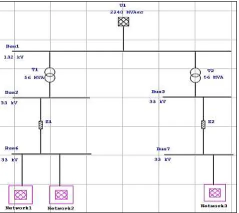
0.69 kV, 1500 rpm machine, the stator resistance Rs is 2.78 ohm with the operating frequency 50 Hz. The Network 1 consisted of 6 WTG’s of 2.1 MW each with a total capacity of 12.6 MW. The Network 2 consisted of 7 WTG’s of 2.1 MW each and the whole network with a total capacity of 14.7 MW. The Network 3 also consisted of 7 WTG’s of 2.1 MW each and a total capacity of 14.7 MW. The total capacity of the Wind Farm thus is 42 MW. The Wind Farm consists of 2 Step-Up Transformers of 56 MVA each. Along with this each WTG have individual Step-Up Transformers of 2500 KVA which was used to Step-Up the voltage from 0.69 kV to 33 kV. Most of the analysis carried out was at Bus 1 of 132 kV near the Utility Grid. The general Layout of the Wind farm is presented in the Figure 1 below.
Figure 1. Layout of the Wind Farm
2. Squirrel Cage Induction Generator
Here the system consists of a combination of a Wind Turbine, Gearbox and a SCIG type machine, where the Wind turbine is connected to a SCIG through a gearbox. The stator terminals of the SCIG are connected to the grid through back to back Converters and the system also consist of coupling inductors. They are used to filter the ripples occurred during Switching [2]. Induction machine generally implies the power being transferred inductively having high conversion efficiency [3]. The rotor consists of cylindrical laminated core with parallel slots for rotor conductors made up of bars of Aluminum, Copper or certain Alloys. The bars are placed in the slots
and bolted to the end rings giving it a Squirrel Cage construction. The rotor bars are permanently short circuited to give it a Cage like appearance and it is practically impossible to add any external resistance. The rotor slots are skewed to avoid any kind of Magnetic locking or humming in the machine [3]. The system configuration of the SCIG Type is presented in Figure 2 below.
Figure 2. Block diagram of SCIG based WECS
III.
RESULTS AND DISCUSSION
1. Simulation And Analysis
A. Load Flow Analysis
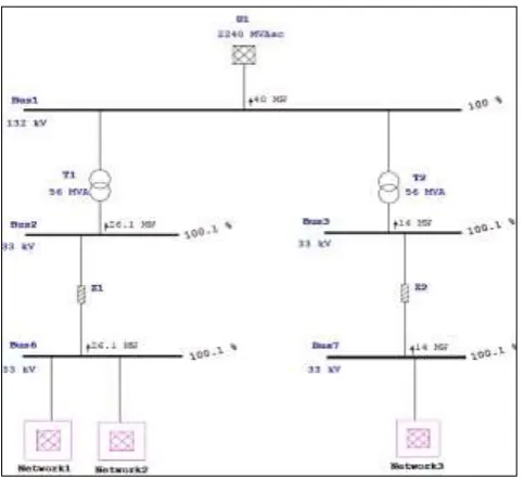
As discussed earlier the total capacity of the Wind Farm is 42 MW. The compatibility of ETAP software is useful in running a Load Flow, where the simulation result presented a total of 40 MW being generated and given to the grid at Bus 1 in steady state. The individual network examination yields a 12.1 MW by Network 1, 14.2 MW by Network 2 and 14.1 MW by the Network 3. It was also found that the Buses were operating in its normal range and no grid code violation was made. The simulation result obtained is shown in Figure 3 and also represented for individual network in Table 1.
TABLE I LOAD FLOW ANALYSIS
Theoretical (MW)
Simulation (MW) Network 1 12.6 12.1
Network 2 14.7 14.2
Network 3 14.7 14.1
Figure 3: Load Flow Analysis
B. Active Power at Various Wind Speeds
The power generated from wind turbines depends on the wind speed in m/s, the Cut-in-Speed of the WTG being 4m/s a simulation study was carried in the Generic model of ETAP, where the Active power for a Wind speed of 4m/s to 14m/s were simulated. There is a direct relation between the Active power and the wind speed. The simulation results obtained from the software are presented in Table 2 as follows.
TABLE III
ACTIVE POWER AT VARIOUS WIND SPEEDS
Wind Speed (m/s) Active Power (MW)
SCIG
4 2.08
5 5.2
6 7.78
7 13
8 18.7
9 26.2
10 32.2
11 34.7
12 39.3
13 40.3
14 41.1
C. Short Circuit Analysis
The Short- Circuit analysis was done to determine the capability of the system to recover from faults. The Wind Farm was subjected to two individual faults a 3- Phase Short Circuit fault and a Single L-G fault. The impact of both these faults was studied and their clearing time was also compared. Both the faults were introduced in the system at Bus 1 at 3 sec and cleared at 3.5 sec.
First a 3- Phase fault was introduced at 3 sec on Bus 1 in the Transient stability study case for a total simulation time of 30 sec. It was found that when this fault occurred the Voltage at Bus 1 dip down almost to 0 kV and the impact was most severe. The possible cause being the current increases in such a condition to a very high level posing a severe impact on the System Voltage. The normal operating voltage of Bus 1 is 132 kV but even though the fault was cleared at 3.5 sec the System Voltage was 123.52 kV at 3.501 sec and finally recovered totally at 4.441 sec with a System Voltage of 132.001 kV. It took +0.94 sec even after the fault clearing to recover 100% of System Voltage. The Voltage drop during the 3 Phase fault at Bus 1 is represented in Figure 4 below.
Figure 4: Voltage at Bus 1 during 3-Phase fault
Figure 5: Voltage at Bus 1 during Single L-G fault Thus the Voltage dipped to 0 kV in a 3 Phase Short Circuit fault and also took +0.94 sec to recover to 100 % System Voltage. Whereas the Single L-G fault dipped to 85 kV and the system took less time to recover. Thus the impact of the 3 phase fault was more and severe and necessary actions were to be taken for system reliability. These were the outcomes of the Short Circuit Analysis.
D. Reactive Power Analysis
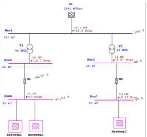
It is well known that the SCIG type machines take the Reactive Power from the grid [6][7]. The Wind Farm was studied for its Reactive Power capability in the software. It was found that the Wind Farm was taking a total of 28.5 Mvar of Reactive Power as shown in Fig 6. There was a need to design a Capacitor bank to compensate this Reactive Power. A Capacitor Bank was designed considering the Mvar’s taken from the grid and the desired Power Factor. The factors considered for Capacitor design included Power Factors, Kvar required, capacitive reactance, Capacitance and Operating Current in Amps.
After the implementation of the Capacitor bank it was found that the Wind Farm was now taking a Reactive Power of 1.93 Mvar from the grid as shown in Figure 7. Thus this clearly demonstrated the use of the Capacitor bank in maintaining the Voltage stability of the system. Where previously the system was taking 28.5 Mvar, after the design and implementation of Capacitor bank it was taking only 1.93 Mvar. This also demonstrates the capability of Capacitor bank in reactive power compensation. The cost of the Capacitor Bank would be a matter of economics but a long term perspective may definitely be helpful in the system efficiency.
Figure 6: Reactive Power Analysis
Figure 7: Reactive Power Analysis with Compensation
IV.
CONCLUSION
of taking VAR’s from the grid. Moreover SCIG machines should be considered because they are robust in construction, have high efficiency, require less maintenance, are less prone to faults and are cost effective too. Thus Wind energy can be more efficiently used by considering SCIG machines for Wind Energy Conversion systems.
V.
REFERENCES
[1] Athanasios Mesemanolis, Christos Mademlis and
Iordanis Kioskeridis, "High-Efficieny Control for a Wind Energy Conversion System with Induction
Generator" IEEE Transactions on Energy
Conversion, Vol. 27, No.4, pp. 958-967, December 2012.
[2] Manaullah, Arvind Kumar Sharma, Hemant
Ahuja, G. Bhubaneswar and R. Balasubramanian, "Control and Dynamic Analysis of Grid Connected Variable Speed SCIG based Wind
Energy Conversion System" 2012 Fourth
International Conference on Computational
Intelligence and Communication Networks, IEEE Computer Society, pp. 588-593, 2012
[3] B.L.Thareja, "A Text Book of Electrical
Technology" S. Chand Publications, vol.2. pp. 1244-1255.
[4] Thomas Ackermann, "Wind Power in Power
Systems" John Wiley and Sons Ltd, pp. 525-584
[5] Roger C. Dugan, "Electrical Power Systems
Quality" Tata McGraw Hill, pp. 197-324, 2012
[6] Manaullah, Arvind Kumar Sharma, Hemant
Ahuja, Arika Singh, "Performance Comparison of DFIG and SCIG based Wind Energy Conversion Systems" International Conference on Innovative Applications of Computational Intelligence on Power, Energy and Controls with their Impact on Humanity (CIPECH14), pp. 285-290, November 2014
[7] Ching-Yin Lee, Li-Chieh Chen, Shao-Hong Tsai,
Wen-Tsan Liu, Yuan-Kang Wu "The Impact of SCIG Wind Farm Connecting into a Distribution System" 2009 IEEE.
[8] Draft Report on, "Indian Wind Grid Code" by