Department of Energy and Technology, Nagoya University, Nagoya 464-8463, Japan
(Received 12 December 2011/Accepted 16 April 2012)
Electron cyclotron heating (ECH) using electron Bernstein waves (EBWs) was studied in the large helical device (LHD). Oblique launching of the slow extraordinary (SX-) mode from the high field side and oblique launching of the ordinary (O-) mode from the low field side were adopted to excite EBWs in the LHD by using electron cyclotron (EC) wave antennas installed apart from the plasma surface. Increases in the stored energy and electron temperature were observed for both cases of launching. These launching methods for ECH using EBWs (EBWH) is promising for high-density operation in future helical fusion devices instead of conventional ECH by normal electromagnetic modes.
c
2012 The Japan Society of Plasma Science and Nuclear Fusion Research
Keywords: electron cyclotron heating, electron Bernstein wave, mode conversion process, high-density opera-tion, heating in fusion device
DOI: 10.1585/pfr.7.2402110
1. Introduction
As a heating method in fusion devices, electron cy-clotron heating (ECH) has a great advantage; that is, the electron cyclotron (EC) wave antennas can be installed apart from the plasma surface. However, for high-density operation in a helical fusion reactor [1], normal electro-magnetic modes cannot access the electron cyclotron reso-nance (ECR) layer, because the electron density is larger than the cutoff density. Conversely, electron Bernstein waves (EBWs) have no density limit in propagation and are absorbed in the ECR layer by cyclotron damping. Thus, at high-density operation, electron Bernstein wave heating (EBWH) is expected to replace conventional ECH by nor-mal electromagnetic modes. EBWs are excited in the up-per hybrid resonance (UHR) layer via the mode conversion process from the slow extraordinary (SX-) mode. There-fore, the electromagnetic waves must be launched from outside the plasma to couple it with the SX-mode inside the plasma.
Experimentally studying EBWH with antennas in-stalled apart from the plasma surface is important for un-derstanding its application in future fusion devices. In the large helical device (LHD), two methods of EBWH with quasi-optical mirror antennas installed apart from the plasma surface have been experimentally studied [2–4]. One method is to launch the SX-mode obliquely to the ex-author’s e-mail: igami@lhd.nifs.ac.jp
∗)This article is based on the presentation at the 21st International Toki Conference (ITC21).
ternal magnetic field from the high field side with the lower port antenna [2, 4]. The other method is to launch the or-dinary (O-) mode obliquely to the external magnetic field from the low field side [3, 5].
This study reports progress on the experimental study of these two methods in the LHD. Section 2 presents exper-imental results for the oblique launching of the SX-mode in a relatively high-density that is still less than the cutoff den-sity. Section 3 presents experimental results for the oblique launching of the O-mode. In Section 4, we summarize our results and briefly discuss applications to a helical fusion device.
2. Oblique Launching of the SX-Mode
Figure 1 shows a schematic of the oblique launching of the SX-mode from the lower port antenna in the LHD. The electromagnetic waves are launched obliquely upward with a large toroidal angle with the polarization of the ex-traordinary () mode; therefore, at first the launched X-mode propagates obliquely to the external magnetic field. The launched X-mode passes near the vacuum vessel wall in the near side of the center of the torus and first encoun-ters the right-handed cutoff(RC) in front of the exterior ECR layer outside the last closed flux surface (LCFS) from the low field side. The electron density and temperature are very low there and the width of the evanescent region be-tween the RC and the UHR layer is very thin; therefore, the launched X-mode may transmit through the region by thec
2012 The Japan Society of Plasma
Fig. 1 Contours of mod B, flux surfaces, the UHR layer, the ECR layer, and the RC plotted on the plane that is par-allel to the z-axis and includes the antenna position and launching vector. Projections of the rays on this plane are also plotted.
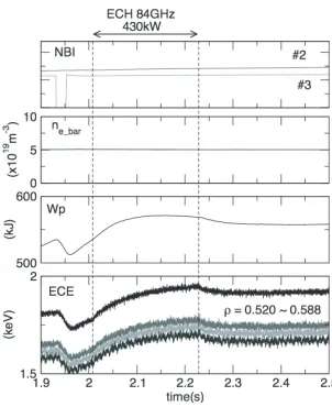
Fig. 2 Time dependences of the following variables (from the top): NBI pulses, line-averaged density, stored energy, and ECE signals.
tunneling effect and reaches the exterior ECR layer. Power absorption in the exterior ECR layer is expected to be very weak; therefore, the X-mode reaches the high field side of the exterior ECR layer, enters the LCFS, and then ap-proaches the interior ECR layer as the SX-mode. If the SX-mode is not completely absorbed in the interior ECR layer, it can reach the UHR layer and is mode converted to EBWs.
Figure 2 shows discharge waveforms when an 84 GHz, 0.43 MW millimeter wave was launched obliquely with the polarization of the X-mode. The magnetic configuration was (Rax, Bt) =(3.7 m, 2.675 T),
where Rax is the position of the magnetic axis, and Btis
the magnetic field strength at the magnetic axis. The target hydrogen plasma was sustained by neutral beam injection (NBI). The stored energy and electron temperature mea-sured by electron cyclotron emission (ECE) radiometer increased after turning on the ECH power. The heating
Fig. 3 Profiles of the local absorbed power (a-1 and a-2) and integrated absorbed power normalized by the launched power (b-1 and b-2) for different launching directions (Rf, Tf). The solid line indicates the absorption of EBWs, and the dashed line indicates the total absorption of EBWs and the SX-mode.
efficiency estimated from the difference of the temporal differentiation of the stored energy before and after turning offthe ECH power was 22.5%. The electron density was less than the cutoff density (8.74×10¹⁹m−3); therefore,
there were two possible mechanisms for ECH: (1) fun-damental SX-mode heating and (2) EBWH. A previous numerical study with ray-tracing calculation suggested that as the electron density at the fundamental ECR layer increases, power absorption of the SX-mode decreases, and the launched SX-mode can cross the fundamental ECR layer without complete power absorption and reach the UHR layer [4, 6]. In that case, EBWs can be excited and EBWH occurs.
Propagation and power absorption of the wave launched as the SX-mode at first were analyzed by us-ing a multi ray-tracus-ing calculation, in which the density profile ne(ρ) =4.7∗(1.0−(ρ/1.1)8)2(×1019m−3) and the
polynomial-fitted experimental electron temperature pro-file Te(ρ) were used, whereρis the normalized minor
ra-dius. The calculation started at the high field side of the ECR layer withωce/ω = 1.01, where ωce is the electron
and the background level (grey) for the same discharge shown in Fig. 2.
close to zero at the ECR layer, and∼10% of the launched power is mode converted to EBWs and the EBWs are ab-sorbed aroundρ=0.8, as shown in Figs. 3 (a-2) and (b-2). If the SX-mode reaches the UHR layer, the nonlin-ear three-wave coupling process can occur. The paramet-ric decay wave in the lower hybrid (LH) wave frequency range excited in this coupling process was determined by using a discone antenna that measures electric field fluctu-ations. Figure 4 shows the frequency spectrum of an LH wave along with its harmonics range. As shown in Fig. 1, the rays encounter the UHR layer before and after they en-ter the LCFS. Misalignment of the toroidal launching angle might increase the power to be mode converted to EBWs in the UHR layer inside the LCFS.
There are possible reasons for the low estimate of the heating efficiency. For example, it is possible that part of the launched beam is lost because it hits the wall. Only power absorption inside the LCFS can increase the stored energy because the energy confinement outside the LCFS is poor. In the case shown in Figs. 3 (a-2) and (b-2), 25% of the launched power is absorbed outside the LCFS. In addition, as suggested in a previous study [4], reflection or mode conversion to EBWs can occur when the launched X-mode first approaches the exterior ECR layer from the low field side. Such phenomena can reduce the incident power.
3. Oblique Launching of the O-Mode
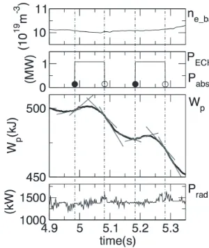
The density gradient normalized by the vacuum wave-length of the EC wave is very large in the LHD. Therefore, to excite EBWs by EC wave launching from the low field side, the O-mode must be launched obliquely to the mag-netic field with an angle such that the plasma cutoffand the left-handed cutoffare very close. In that case, the O-mode is O-mode converted to the SX-O-mode, propagates to the UHR layer, and is mode converted to EBWs (the O-X-B mode conversion process). It has been difficult to deter-mine the effect of heating on the change in the stored en-ergy and electron temperature profile with low-power ECH (∼300 kW) in high-density plasmas [3]. We expected to beFig. 5 Time dependences of the following variables (from the top): line-averaged density ne bar; ECH pulse PECH(solid line) and estimated absorbed power Pabs(black and white circles); stored energy Wp(black line) and linear fittings of the stored energy before and after turning on and offof the ECH pulse (grey lines); and radiation loss Prad.
able to determine this effect more clearly because of the installation of the high-power (∼1 MW) 77 GHz gyrotron.
In previous numerical studies [7, 8] of EBWH via the O-X-B mode conversion process using the existing hori-zontal port antenna, it was suggested that the power ab-sorption region shifts toward the plasma core as the exter-nal magnetic field decreases. However, it was also sug-gested that the “O-X-B mode conversion window” of the aiming point of the launched EC wave is blocked by the wall of the horizontal port when the magnetic field strength decreases [8]. In our experiment, we first selected the mag-netic configuration (Rax, Bt)=(3.75 m, 2.2 T) and launched
the O-mode. Figure 5 shows the discharge waveforms for our experiment. The target helium plasma was sus-tained by NBI. The line-averaged density was larger than the cutoffdensity of 77 GHz (7.35×10¹⁹m−3). As shown in Fig. 5, the gradient of the linear fittings of the stored en-ergy (gray lines) increases after turning on the ECH power and decreases after turning it off. This suggests that the input power to the plasma depends on the ECH power. Ra-diation loss increases slightly upon turning on the ECH power; however, the effect on the change in the stored en-ergy is insignificant. The heating efficiency estimated from the difference of the temporal differentiation of the stored energy before and after turning on and offthe ECH power is∼15% on an average.
Figure 6 shows a contour plot of the O-X-B mode con-version rate as a function of the aiming point on the virtual upright plane placed at R=3.9 m (the center of the vac-uum vessel); this plot determines the launching direction as (Tf, Zf)=(0.75 m,−0.34 m), which corresponds to the
case shown in Fig. 5. Note that Tf is the distance along
sec-Fig. 6 O-X-B mode conversion rate plotted as a function of the aiming point on the virtual upright plane at R=3.9 m. The point where the two dashed lines intersect corre-sponds to the discharge setting shown in Fig. 5.
Fig. 7 Projection of the rays onto the plane sliced at z=−0.2 m.
tion, and Zf is the distance from the equatorial plane. The
O-X-B mode conversion rate TOXB was calculated with
Eq. (1) [9] (below) at the point where the perpendicular component of the refractive index is at a minimum near the plasma cutoffor the left-handed cutoffin the ray-tracing calculation.
TOXB=exp
−π(ω/c)Ln(β/2)1/2
×[2(1+β)(N//−N//opt)2+Nv2]
, (1)
Ln: scale length of the density gradient,
N//: parallel refractive index,
Nv: refractive index perpendicular to the magnetic field
and density gradient,
N//opt={β/(1+β)}1/2, whereβ=Ωce/ω,
Ωce: electron cyclotron angular frequency,
ω: angular frequency.
In the ray-tracing calculation, an electron density pro-file of ne(ρ)=8.7∗(1.0−(ρ/1.0)20)2(×1019m−3) was
con-sidered. According to Fig. 6, TOXB ∼20%, which is
sim-ilar to the estimated heating efficiency obtained with the experimental setting. Figure 7 shows the ray propagation before and after the O-X-B mode conversion. After the mode conversion in the peripheral region, the wave prop-agates toward the core region. As shown in Fig. 8, a part
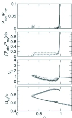
Fig. 8 Radial dependence of the following variables (from the top): local absorbed power, integrated absorbed power normalized by the launched power, parallel component of the refractive index, and electron cyclotron angular frequency normalized by wave angular frequency. Ex-amples of the ray at the beam center and rays at the 1/e radius are plotted.
of the power is absorbed aroundρ = 0.3, and the rest is absorbed aroundρ = 0.9 where the Doppler-shifted res-onance condition is fulfilled. In a different discharge with (Tf, Zf)=(0.85,−0.37), the electron temperature measured
by ECE radiometer in the core region (ρ∼0.2) increases after the ECH power is turned on. In these experiments, measurement of the parametric decay wave in the LH wave frequency range was not performed. However, the only possible heating mechanism is the EBWH in the Doppler-shifted ECR layer.
4. Discussion and Summary
quantitatively. For oblique launching of the O-mode, it is important to place the antenna to aim for the mode con-version window. In addition, to efficiently heat the core region, it is important to choose the wave frequency such that the UHR layer is near the core region.
[5] H.P. Laqua et al., Phys. Rev. Lett. 78, 3467 (1997). [6] H. Igami et al., Plasma Sci. Technol. 11-4, 430 (2009). [7] K. Nagasaki and N. Yanagi, Plasma Phys. Control. Fusion
44, 409 (2002).