DESIGNING & ANALYSIS OF COMB DRIVES USING DIFFERENT MATERIALS
Kuldeep Bhardwaj1* Parveen Kumar21*Asso. Prof. ECE dept. OITM COLLEGE JUGLAN HISAR 2M.tech scholar ECE dept, OITM COLLEGE JUGLAN HISAR
Correspondence Author:[email protected]
Keywords:Mems, comsol, ale, fem
Abstract
This paper brings in the design of MEMS electrostatically actuated by a rectangular comb drives. By using different structural materials, the comb geometries are designed and there result is analyzed. Finite element analysis is used to establish the concept of controlled displacement of the movable comb fingers, achieved by setting down the amount of electrostatic force produced by the device and to reduce power consumption, PMMA and PTFE polymers produces high displacement at very low voltage as compared to Poly-Si.
Introduction
Capacitance based actuators have been widely used in MEMS devices. Among different devices, the most commonly used and examined is the comb drive. The MEMS comb drive is a laterally driven mechanical actuator activated by electrostatic interact ion. A typical rectangular shaped comb drive design involves simple fabrication steps and it is characterized by low power consumption. [1, 6].
Designing of comb drive
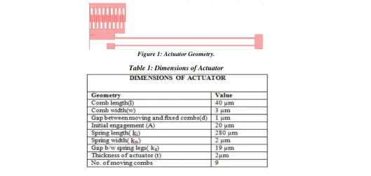
The coupled electrostatic-mechanical problem is solved by a FEM parametric study, which uses the ALE formulation. All modeling is performed in the FEM software package COMSOL using three multiphysics modes: electrostatics, plane stress and moving mesh. The base material used for structural part is polysilicon as it has excellent mechanical properties and its electrical properties can be modified by doping boron or phosphorous [2, 4]. The designs have few dimensions in common except the distance between the fixed and movable combs numbers of comb fingers. The dimensions of the actuator are shown in table 1. There are three main design ingredients in the structure designed fixed combs, movable combs and folded spring as shown in figure 1. It consists of 10 fixed combs which are grounded as this type of actuator work on the principle of electrostatic actuation so, it is necessary to develop negative and positive charge in the fixed and movable combs. Due to this reason the fixed combs are grounded. As the electric potential is applied to the movable combs an electrostatic force is generated which provides the actuation in the direction of the length of the comb fingers.
Figure 1: Actuator Geometry.
In the folded flexure spring the beams are anchored near the movable combs and the bind allows expansion or contraction of the beams along axis. This spring exhibits a much larger linear deflection range so it is suitable for large deflection actuators. Another important effect that is considered is the stiffness of the folded flexure beam in the x-direction reduces with increasing displacement in y- direction [3, 5]. The fixed combs are grounded and the electric potential is applied on movable combs. Applying a voltage difference between the comb structures will result in a deflection of the movable comb structure by electrostatic forces as shown in the figure.1.2. This deflection causes change in area between the combs, as the overlapping area changes, the capacitance between the fixed and movable combs changes. The capacitance can be expressed as in equation 1.
𝐶 = 2𝑛 ∈0 ℎ(𝑦 + 𝑦0)
𝑑 (1)
Where, n is the number of combs, ε̥ is the dielectric constant in air, h is the height of the comb fingers, y̥ is the initial comb finger overlap, y is the comb displacement and d is the gap spacing between the comb fingers and V is the applied voltage between the movable and fixed combs.. The lateral electrostatic force in the y-direction can be expressed in equation 2 as:
𝐹𝑒1=
1 2
𝜕𝐶 𝜕𝑦𝑉2=
𝑛 ∈0ℎ
𝑑 𝑉2 (2)
We have used three different materials for designing comb drive and their properties are as follows in table 1.
TABLE 1: Properties of material used for cantilever design
Material Young’s
Moduls Possion Ratio Density
Poly-Si 160e9[Pa] 0.22 2320[kg/m^3]
PMMA 3e9[Pa] 0.40 1190[kg/m^3]
PTFE 0.4e9[Pa] 0.40 2200[kg/m^3]
Results
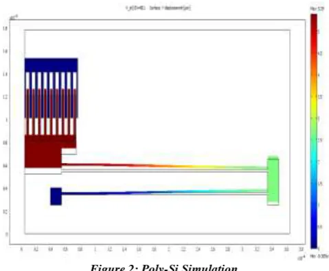
Figure 2 shows simulation result of structural material Poly-silicon this design shows maximum displacement of 5.38 μm at 80.1V (maximum voltage) and displacement of 3.82 μm at 60.1V
Figure 2: Poly-Si Simulation.
Figure 3: Poly-Si Curve.
Figure 4 shows simulation result of structural material PMMA this design shows maximum displacement of 3.74 μm at 8.1V (maximum voltage).
Figure 4: PMMA Simulation.
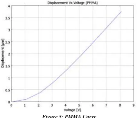
Figure 5 shows the response of the PMMA comb drive, by this we can analyze that PMMA produces very good displacement at very low voltage the displacement changes slowly from 0 to 2 V and it increases sharply after 2 V till 8.1V voltage at produces 3.74 μm displacement. By using PMMA we are able to reduce the voltage level to nearly ten times less. PMMA produces nearly same displacement as produced by poly-si i.e. 3.75 approx at 8.1 V which poly-si produces at 60.1 V.
Figure 5: PMMA Curve.
(maximum voltage).
Figure 6: PTFE Simulation.
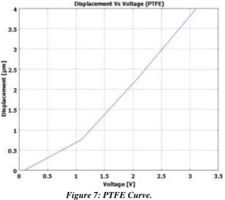
Figure 7 shows the response of the PTFE comb drive, by this we can analyze that PTFE produces very good displacement at very low voltage the displacement changes slowly from 0 to 1 V and it increases sharply after 1 V till 3.1V voltage at produces 4 μm displacement.
Figure 7: PTFE Curve.
Conclusion
It can be concluded that by using PTFE as strutrual material we can able to reduce the actuation voltage of comb driveto 3.1V as compare to PMMA which required 8.1V for nearly same displacement and by using PMMA we are able to reduce the voltage level to nearly ten times less that of Poly-Si. PMMA produces nearly same displacement as produced by poly-si i.e. 3.75 approx at 8.1 V which poly-si produces at 60.1 V
References
1. Farshad Shadbakhsh1, Mohammadali Shahriari, Abolghasem Zabihollah, “ Conceptual Design of a Micro Gripper with Electrostatic Micro Stepper-Motor Actuation”, Life Science Journal, pp 290-293, 2013.
2. Anurag Singh and Vijay Kumar Anand “Simulation of Shaped Comb Drive as a Stepped Actuator with Improved Slippage for Microtweezers Application”. Journal of Information Systems and Communication, Volume 3, Issue 1, pp.- 179-181, 2012. 3. Binglei Wang and Shenjie Zhou; “Size Dependent Pull-in Instability of Electrostatically Actuated Micro Beams based on
MEMS”, Journal of Micromechanics and Microengineering, Vol. 21 No. 2, pp 304-309, Feb. 2011.
4. Zakri Ghazalli, Asnul hadiahamad, Mohd Fazli Ismail and Khairul Fikri Muhamad “Design of Electrostatic Comb Actuators Based on Finite Element Method” International Conference on Enabling Science and Nanotechnology, Malaysia, pp 1-3,Dec. 2010.
Study”; Excerpt from the Proceedings of the COMSOL Conference, Boston, pp 317-322, 2010.