3687
Performance Analysis Of SDN-Based Proxy
Mobility Support Scheme In E-Health
Environment
Abdelwahed Berguiga, Ahlem Harchay, Ayman Massaoudi
Abstract: In this paper, we propose a new architecture of the proposed 6LoWPAN mobility management protocol. Our proposal scheme, named FPMIPv6-S+, is a an enhanced of the protocol FPMIPv6-S [1] that uses the SDN paradigm with the OpenFlow protocol. We combine the characteristics of FPMIPv6-S mobility management protocol and the SDN network architecture to enhance the handover process of nodes in mobile scenes. The FPMIPv6-S+ architecture implements a centralized SDN controller that manages user’s mobility. Indeed, when a MN changes location the controller will be notified in order to reconfigure the network.
Index Terms: Wireless Sensor Network, 6LoWPAN, Mobility support protocol, Comparative study
—————————— ——————————
1.
INTRODUCTION
IN today’s world of connectivity, the field of Internet of Things (IoT) is increasingly being a fast developing technology which opened new paths in our life and allows humans and things to interconnect anywhere and anytime. It is used to connect things to the Internet from a wide variety of sectors such as smart factory networks, home automation, medical monitoring, building automation, and E-health field. Indeed, Smart wearable devices such as blood pressure, Electrocardiogram (ECG), blood glucose, temperature sensors are examples of things which enable remote health monitoring of patients by collecting data about their health status. Then, gathered data are sent toward an authorized medical staff to be analyzed, take proper decisions and offer preventive measures according to the received values. Hence, mobility healthcare is still a major challenge to the Internet of Things due to the energy constraint requirement, as well as very low memory capacity of such sensors. To support mobility in IoT devices, there is a need for the development of new mobility protocols in order to monitor patients where they can be connected anytime and anywhere in mobile networks. Also, any mobility management scheme must take into account some parameters to be minimized as maximum as possible such as the signaling cost, memory, power consumption, and handover delay [2, 3, 4, 5]. Indeed, the need to provide Internet connectivity to these devices with IPv6/6LoWPAN networks in order to provide seamless connections among millions of devices and take full advantage of exiting Internet architecture and protocols has led to the design of 6LoWPAN protocol suite. Due to the heterogeneity of the overlap between different mobile networks, any proposal mobility management scheme should offer some techniques to reduce the handover delay and connectivity interruption. Accordingly, the IETF has proposed a Mobile IPv6 and its variants of host-based networks for managing mobile mobility in IP layer. However, some disadvantages have been found in these
protocols, especially adding up extra delay operations including tunneling overhead, triangular routing, and duplicate address detection [6]. To reduce the extra delay operations overheads of these resource constrained, the IETF (NETLMM) working group has proposed a mobility management protocol, called Proxy Mobile IPv6 (PMIPv6) [7]. PMIPv6 has been proposed to provide network-based IP mobility management without the involvement of the Mobile Node (MN). PMIPv6 infrastructure offer two principles entities, the Local Mobility Anchor (LMA) and the Mobility Access Gateway (MAG). However, some inherent problems such as bottleneck risk at the LMA, more resources and the required of a large buffer size at the MAGs which lead in degraded performance. Therefore, taking this into account, we propose in this work a new network solution that depends on Software Defined Networking (SDN) and to adapt into E-health environment. SDN is a network architecture that opens new trends to eliminate the rigid nature of traditional networks [8]. SDN divides the network architecture into two planes, namely control plane and data plane. SDN can show suitability and flexibility in the global mobility required in the E-health environment. It supports the programming capability of the network infrastructure through an open Application Programming Interface (API).
This paper proposes a new network solution, which combines the advantages of Fast handover proxy Mobile IPv6 for sensor networks (FPMIPv6-S) [1, 9] with SDN architecture so that user mobility can be managed seamlessly in a heterogeneous IP access networks. The proposed solution considers several metrics when mobile node change L2 Network and change the Access Point (AP) attachment. We evaluate the performance of our proposed architecture using the protocol FPMIPv6-S analytically. Analytical results show that the proposed scheme is aimed to offer a feasible implementation, reduce signaling overhead in making local and global handover decisions as well as the deployment mobility management proposal for 6LoWPAN based IoT networks. The reminder of this paper starts with an outline of an extensive related work of the proposed solutions related to IPv6-based mobility management protocols. Then, the proposed 6LoWPAN-based mobility management scheme, FPMIPV6-S+, is described in Section III. The analytical models for performance evaluation are presented in Section IV. The network-based mobility management protocols such as PMIPv6 and FPMIPv6 are analyzed and compared in terms of binding update cost and ————————————————
Abdelwahed Berguiga: Computer Science Department, Jouf University, Sekakah, Saudi Arabia. E-mail: [email protected]
Ahlem Harchay: Computer Science Department, Jouf University, Sekakah, Saudi Arabia. E-mail: [email protected]
3688
packet delivery cost. The results of qualitative analysis and quantitative analysis are presented, plotted and discussed in Section V. Finally, the conclusions are given in Section VI.
2
RELATED
WORKS
2.1 Mobility Management Protocols
2.1.1 Mobility over IPv6 networks
Due to explosive increase of demand for new wireless network and the consequential user’s mobility among different domains, diverse mobility management protocols has been proposed. Mobility management is a challenging research issue in Internet of Things that demands further investigation. In particular, it requires a lot of effort from researchers to address challenges of 6LoWPAN objects in term of mobility management in heterogeneous access networks and according to user’s location in order to maintain their connection state when moving from one attachment point to another attachment point. Mobility can be used to extend and maintain network connectivity. This mobility can be physical or logical. Physical mobility refers primarily to changes in the geographical location of an entity over time, while a logic mobility refers to dynamic changes in network topology such as the addition or deletion of new entities in the system. When a mobile device changes its network, it must retrieve necessary settings to ensure reliable and efficient communication with other devices on that network. In particular, the node must resolve the prefix of the network used and its size. Equipped with the prefix granted by the new network, 6LoWPAN node is then able to perform necessary operations for auto-configuration or request a new IP address (Care of Address: CoA). Without this new IP address, mobile node cannot perform certain expected operations, such as responding appropriately to the various multicast/unicast messages. Once the 6LoWPAN node has successfully registered with the new network, it can perform data exchange operations either with its home network or with nodes in the new network. However, in many cases, access to the new network is denied unless the mobile node is able to provide authentication information to prove that it is authorized to make use of the physical resources of the visited access network. In a nomadic context, regardless of the nature of mobility, an auto-configuration of the network is necessary. This self-configuration requires relevant methods to maintain communication in poor network coverage areas and thereby maximize network performance. However, the insurance of mobility services in these networks poses non-trivial research problems given the nature of wireless transmission, resource’s limitation and the dynamic character of the topology of these networks. Thus, in a context where a 6LoWPAN sensor node moves towards a new network while remaining in communication with other nodes located in other IP networks, makes it necessary to propose mobility management protocols adapted to the constraints of 6LoWPAN nodes and desired applications. IETF has proposed protocols for mobility management in traditional IP networks. Some are based on the network as Proxy Mobile IPv6 [7]. Others are host-based like Mobile IPv6 [10].
a) Mobility over IPv6 networks
One of the most representative efforts in mobile IP networks is Mobile IPv6 (MIPv6) [10]. MIPv6 has been defined by the IETF-MOBILEIP working group. It has been proposed as a
host-based mobility protocol that supports the global mobility of MNs in IPv6 networks. When a 6LoWPAN node moves changes its attachment point, it discovers the Foreign Agent (FA) by receiving Router Advertisement (RA) messages. After authentication with this FA, mobile node builds a temporary address, named Care of Address (CoA), through the auto-configuration mechanism. Then, the MN sends an update message to its Home Agent (HA) called Binding Update (BU). This message includes both the temporary address and the home address. HA save the MN Care of Address (CoA) and associates with its Home Address (HoA). Then, this home agent will intercept packets destined for the MN, encapsulate them and send them to the foreign agent. When the datagrams reach the new network, the foreign agent de-encapsulates the datagrams and delivers them to the mobile node. However, packets sent by the MN and intended for Correspondent Node (CN) are generally delivered using standard IP routing and not necessarily traversing the HA. This mechanism is known as triangular routing. In addition, deploying MIPv6 leads to some inefficiency issues in terms of security, efficiency, and packet loss. In order to gain better performance than MIPv6 and to address such issues, several enhanced schemes are suggested to support node and network mobility including Hierarchical MIPv6 (HMIPv6) [11], HMIPv6 is based on a hierarchical model and introduces a new agent names Mobility Anchor Point (MAP) to coordinate the movement of MN in a Foreign Network (FN) and manage local handover. A set of APs and their MAP constitute a MAP mobility domain. HMIPv6 suggests that mobile node in a foreign network communicates the MAP’s address to the HA. Unlike MIPv6, in HMIPv6, HA tunnels MN’s data to MAP instead of MNs’ actual CoA. This mechanism aims to reduce the handoff delay and the overload of the level 3 handoff-related signaling. HMIPv6 has the advantage compared to MIPv6 to limit the number of signaling messages during intra-domain movements. In addition, the deployment of a MAP hierarchy made it possible to make movements of the MN transparent to its home agent as well as the corresponding nodes, given that messages of type Binding Update (BU) will only be exchanged locally within the MAP. In this, these entities tracks the mobility of nodes and initializes the mobility signaling procedure. In other words, to provide mobility transparency, all exchanged messages between the MN and HA (or between MN and CN) must go through the mobility anchor point. However, increasing the session number between an MN and CN, leads to increase the delay of data packets delivered to the MN. On top of that, a complete failure can be seen on the MAP if the number of MNs increases rapidly. Also, inter-domain handover was not considered by HMIPv6. Another problem raised when deploying the HMIPv6 protocol is the requirement of the association of the IPSec protocol [12] between the different entities which introduces significant problems in terms of code size, cause memory overflow which is unsuitable for IoT networks. Another issues of such solution, is the involvement of MNs on mobility management which given that the global handovers occur in same manner as in MIPv6, which may result in excessive energy consumption for energy-limited MNs.
b) Network-based mobility management schemes
3689
and make the motion tracking of the host so the pressure of MN is alleviated. Two protocols are suggested based on this fact, namely, NEMO [13] and PMIPv6. In PMIPv6, handover procedure is performed by a new network entities named mobile access gateway (MAG) instead of MN, and a local mobility anchor (LMA) instead of HA. MAG handling the mobility-management signaling on behalf of MN and the LMA acts as a home agent of MN. Indeed, LMA is responsible for managing location status of MN and establish a bi-directional tunnel to forward packets between MN and its CN(s). Meanwhile, when the MN change it’s attachment point, MAG detects MN’s access and receive MN’s configuration parameters such as user’s ID, service provider’s ID, and LMA’s address. Then, MAG send a Proxy Binding Update (PBU) to LMA on behalf of MN. Upon receiving the PBU message, LMA reply by sending Proxy Binding Acknowledgement (PBA). PBA contains, among others, MN’s home network prefix, and accordingly the LMA update the MN’s binding cache entry (BCE) to keep track of the new attached MAG. As soon as the MAG has received the PBA, it sends router advertisement (RA) to MN and establish a bidirectional tunnel with LMA. Once the MN receives the RA, it configures its new IPv6 address and then it is able to exchange data with CN through this bidirectional tunnel. In spite of that, on the deployment of network mobility management schemes, there are many issues to be resolved in order to provide seamless mobility and guarantee quality of services (QoS) to smart object connected anywhere anytime. The first issue of PMIPv6 does not support user smart devices authentication/registration process in inter-domain and intra-domain of PMIPv6 [14]. Furthermore, every time the node attached to a new MAG, it need to be authenticated via AAA server. For example, if we have several MAGs on a proxy domain, and the MAG don't have enough information about the MN, this last must perform repeatedly registration/ re-authenticate to their MAG in each network area as well as LMA. This process will lead to rapid depletion of battery resources due the control messages exchanged to synchronize with the new access router and will generate long handoff delay. The second issues is that during the exchange of PBU and PBA messages (handover period), a certain amount of handover delay is experienced which leads packet loss, which affects the performance of the entire network. To overcome problems of PMIPv6, multiple heterogeneous handover schemes [15, 16], have been proposed. Most of them combine IEEE Media Independent Handover (MIH) framework with PMIPv6, and deploy new entities and mechanisms. Chiang et al. [17] integrated MIH with PMIPv6 in order to ameliorate handover performance such as packet loss and handover delay. More recently, Alves et al. [18] proposed a solution to deploy the coordination between PMIPv6 and MIH in real testbed in order to support the flow mobility. The proposed solution is only deployed at the network side and it extends Proxy Mobile IPv6 with flow mobility in a completely transparent way to mobile nodes. Huang et al. [19] extended the PMIPv6-based schemes by integrated it into MIH to provide a group-based handover preparation for MN to eliminate the handover latency and the signaling cost causing by redundant re-registrations/re-authentications. In [20] authors introduced a multi-node handover method 6LoWPAN devices over PMIPv6. The proposed scheme used the bulk binding update standard, which defines multiple sessions handovers. As a result, it can have the better performance in
terms of MNs’ handover overhead. Michalas et al. [21] has proposed an integrated MIH-FPMIPv6 in evolved-packet system by introducing the MIIS function to support the handover. Zhang and Tian [22] has proposed an enhanced fast handover triggering mechanism for FPMIPv6. Indeed, an adaptive RSS threshold mechanism is used to predict the handover mode and set up the tunnel in advance. Likewise, other work focus on combination of DMM and MIH [23], Multi-homing [24] and security. Even though the protocols such as MIPv6, FMIPv6, and HMIPv6 help to support mobility by using different metrics, and even though PMIPv6 offer minimum latency and reduces signaling cost to provide better handover, there is chance for all existing protocols the termination of connection during handoff period and packet loss. Accordingly, this restricts their usage in some applications such as real-time applications and 6LoWPAN networks. Likewise, when these protocols are applied with 6LoWPAN networks there are many problems will be appeared due to energy and resource constrained. Indeed, enabling mobility related IP protocols in these devices could deplete power resources by antenna consumption due the control messages exchanged to synchronize with the new access router [25]. Consequently, these protocols are not a good recommendation for LLNs. Therefore, the investigations were going on to find the extensions to these protocols in order to make it suitable for low power networks.
c) Mobility over 6LoWPAN networks
3690
support for the WSN. A new stability metric was proposed using the prediction model to build links according to topology changes [32]. In the paper [33], Bouaziz et al. introduced a proactive routing protocol to support probability named EKF-mRPL. The main aim of this scheme is to use the extended Kalman filter to predict the non-linear movement of the MN. The new preferred parent node was selected based on the movement direction of the MN with the extended Kalman filter. However, these models consumed significant power that reduced the network lifetime as the nodes had low processing capacity and low power. In addition, the protocol has an issue on selecting a new point of attachment when the node changed its position randomly. In [34], authors have proposed a modified energy efficient RPL where velocity and angle between the preferred parent and the MN are calculated based on the Doppler frequency. They dynamically adjusted the transmission interval of controlled messages based on the direction and MN velocity. However, the protocol suffered from the sudden changes in the MN position, which increase the packet loss rate. Another recent work proposed by Wang et al., so called SMH [35]. The proposed scheme introduce a seamless mobility handover concept in 6LoWPAN networks and use static nodes to handles movements of mobile nodes. A tree structure use built to facilitate the mobility handling. However, this approach does not consider the failure of the static nodes, which causes the mobile node dis-connectivity from the access point.
2.1.2 SDN-based mobility management schemes
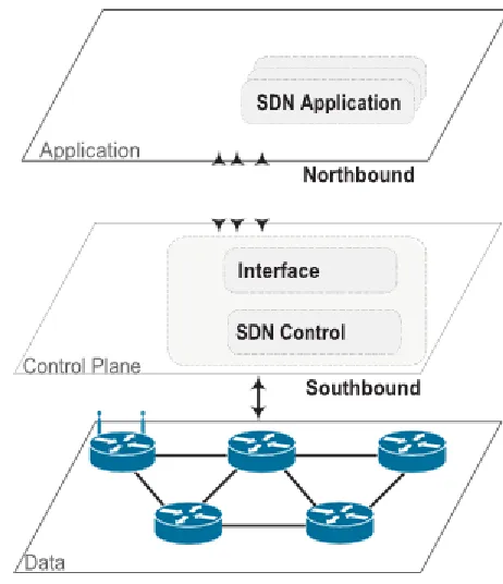
Despite the deployment of legacy Mobility management protocols and the introduction of new entities such as MAP [11], LMA [7], SLMA [25], MR [29], CPN [32] or new metrics such as [31] and [33] all solutions suffer from issues of performance, latency costs and scalability. However, the recent advances in Software Defined Networking (SDN) have provided opportunities for adaptable network deployment. SDN represents an emerging paradigm that defends the separation of control and data plane in networks. Indeed, SDN offers the ability to decouple the network’s control logic from switching, routing, firewall security rules, clustering, thus improving the ability to manage the network state. Many long-awaited features are enabled by SDN such as on-demand resource allocation, self-service provisioning and truly virtualized networking through its intelligent orchestration and provisioning system. Subsequent the definition of the Open Networking Foundation, SDN's architecture can be subdivided into three distinct layers: 1- application plane, 2- control plane, and 3- data plane. As shown in Figure 1, communications between SDN layers is ensured between southbound interface and northbound interface. Southbound interface enables communication between data layer and control layer and northbound interface is between control layer and application layer. Southbound interface provides (i) programmatic control of all forwarding operations, (ii) capabilities advertisement, (iii) statistics reporting, and (iv) event notifications [36]. The data plane in a SDN is composed of various networking devices such as routers, physical/virtual switches, access point, etc. it is responsible for exporting the user’s network packets to the output port by referring to the destination address. Indeed, data plane can provide a respectable agility of 6LoWPAN networking by enabling a rule-based of individual data flow and forwarding traffic according to the decisions made by the controller located on the control plane. In fact, the controller
acts as a brain and manages the network by having a global view of the network. It can be considered as one of the cornerstones of SDN where it makes forwarding decisions with real-time global information and configures forwarding rules at devices located at data plane (switches, routers, etc.). Hence, the SDN controller generates network configurations based on arrangement defined by the network operator.
Fig. 1. Software-defined networking (SDN) layers
It manages the whole network and possesses a global view of the network by supervising the network forwarding behavior. The controller abstracts the network’s lower-lever details such as network topology, state, device discovery, etc. In doing so, diverse set of controllers are used by control plane each with their own design and architecture as shown in table 1.
TABLE1. CONTROLLER’SFUTURES
Controller name
NOX POX RYU Flood
light
OpenDa yLight
Language C++ Pytho
n
Python Java Java
Performance High Low Low High High
Distributed No No Yes Yes Yes
OpenFlow support version
1.0 1.0 1.0-1.4 1.0 1.3
CloudSupport No No Yes Yes Yes
Learning Medium Easy Medium Hard Hard
3691
application.
3
PROPOSED
FPMIP
V6-S+
ARCHITECTURE
This paper proposes the FPMIPv6-S+ architecture, which integrates the OpenFlow with the PMIPv6. Figure 2 illustrates the scenario deployed in this study. Thus, we consider the case of a medical monitoring application where there is a whole system capable of monitoring the physiological characteristics of patients. Patients carry wireless sensors each characterized by its own monitoring task. The technology used by the sensors is IEEE 802.15.4.
Fig. 2. 6LoWPAN and SDN-based architecture for remote healthcare monitoring
We consider a clinic building consisting of three floors. Patient can move from one floor to another floor. Each floor is composed of a number of rooms. Each room includes a wireless switch that acts as a MAG. Each switch has a coverage area of 20 meters and identified by the number of the floor and its number in the floor. Furthermore, the main role of the switch is initialize of mobility-related signaling with the SND controller. Inside the clinic, patients are mobile. They carry wireless sensors that monitor some of their vital signs. One of the body sensors is selected as a coordinator. The coordinator is a full-function device (FFD) which has the responsibility to receive all data collected by other sensors attached to the patient and forward them to the switch. Obviously, the coordinator must have a capacity greater than or equal to the other sensors (storage, calculation, energy, etc.), and it is chosen manually or automatically according to a given algorithm. Patients can move openly between clinic rooms. Sensors wired by patient form a wireless body area network (WBAN). Data collected by the sensors are sent to an authorized medical staff which monitor residents locally at the hospital or remotely. The proposed architecture is shown in Figure 2.
3.1 FPMIPv6-S+ procedural rules
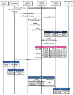
In this part, we focus on the description of the different signaling messages exchanged when the patient changes it’s attachment point. According to the domain mobility in which the patient moves, local mobility can be classified into intra-mobility management, and domain intra-mobility can be classified into inter-mobility management. Figure 3 shows the time sequence diagram when a patient performs an intra-mobility handover. We can distinguish 8 steps:
• Step 1 and 2: when a patient (6LoWPAN node) enters the coverage area of a new access point attachment point (new switch/MAG: n-SMAG), and if it wishes to select it as an appropriate parent, it sends a request message of association ("Association Request"). Upon receiving this request, the new switch (n-SMAG) replies by sending an Association Response message. In several types of applications such as healthcare monitoring, it is conceivable for a patient to carry several body sensors in order to monitor and control his physiological parameters such as temperature, pulse, blood pressure and other complementary parameters. In such a scenario, instead of each sensor sending its own association message, a particular node, the most powerful one, could play the role of the group coordinator. It will be the only one that can proceed the attachment procedure by sending and receiving signaling messages. Therefore, the control message contains the following components: <Header, p-Switch@, AssociatedSensorNumbers, , 𝑀𝑁 − 𝐼𝐷, 𝐿𝐿 − 𝐼𝐷,
𝑀𝑁 − 𝐼𝐷, 𝐿𝐿 − 𝐼𝐷 ,..., 𝑀𝑁 − 𝐼𝐷 , 𝐿𝐿 − 𝐼𝐷 >, where :
p-Switch@ : is the address of the switch to which the mobile node is already adhered.
AssociatedSensorNumbers: is the number of sensors attached to the coordinator.
𝑀𝑁 − 𝐼𝐷 and 𝐿𝐿 − 𝐼𝐷 : are respectively the identifier of the sensor and the link layer identifier (Link Layer). • Step 3: As soon as the new Switch receives the association request message, the update mechanism in the new PAN commences. Indeed, his first task is to transfer this message to his Controller entity (SLMA). Then, the controller extracts the address of the previous MAG (p-SMAG) which is serving the node 6LoWPAN. Based on its local neighborhood table, the n-SMAG can determine the address of the old SMAG (previous SMAG: p-SMAG) to which the coordinator is attached. The n-SMAG began the exchange of handoff information by sending a Handover Initiate (HI) message to the p-SMAG entity. The HI message contains the address of the SLMA whose n-SMAG is attached.
• Step 4 and 5: Upon receiving the handover initiate message, the p-SMAG entity verifies if the new SMAG resides on the same PMIPv6 domain (i.e. intra-mobility procedure). If it does, the p-SMAG updates its routing table and responds by an acknowledgment message (Handover Acknowledgment: HAck). Then it sends the update message "SBU" to the SLMA home agent. This message is sent on behalf of the n-SMAG entity.
• Step 6: Once the controller receives the sensor binding update message, it performs the authentication-related signaling with the SLMA on behalf of coordinator. After successful authentication from AAA, SLMA allocates Home Network prefix (HNP) to coordinator and updates its Binding Cache Entry (BCE). Then, it binds the coordinator’s IP address with the Proxy-Care-of-Address (PCoA). The Proxy-CoA is the global address configured on Switch (SMAG). Then, the controller sets up bidirectional tunnel with SMAG. From this instant, the coordinator can send or receive data traffic through Proxy-CoA, and traffic sent from the LMA gets routed to coordinator through the established tunnel.
3692
properly. Then, the n-SMAG sends to the 6LoWPAN node a Router Advertisement Fast Proxy (RtrAdvFP) message which containing its Home Network Prefix (NHP). RtdAdvFP is an extended version of the "Router Advertisement" message containing the following components: <Header, ICMPv6, CoordinatorID, HNP1, HNP2, ..., HNPn>, where HNPi is the Home Network Prefix of node i.
Figure 3: FPMIPv6-S+ handover procedure
4
PERFORMANCE
EVALUATION
4.1 Analytical evaluation
In this section, performance of our proposed mobility management scheme is evaluated analytically based on L2 triggering time 𝑡 , which is the time taken from the occurrence of the L2 trigger event to the start of the real L2 switching process. Indeed, in 6LoWPAN-based mobility management, QoS can be defined as the packet loss rate, handoff latency, and handover cost due to signaling messages exchanged during changing the attachment point. Analysis of these metrics is more than necessary to check the performance of mobility management protocols in 6LoPWAN-based mobile environment. Handover is initiated by L2 trigger which events to layer 3. Subsequently, an L2 event occurs when there is a change in the signal strength of one or more access points. The time when layer 3 is notified from the L2 event is determined by the threshold value of the signal strength used in the protocol implementation. Furthermore, given Ps as the handoff prediction rate, this probability variable, Ps, depends of triggering time 𝑡 , which is highly random. In this case, the value of Ps, which indicates the probability that L3 handover really occurs after the L2 trigger. If we suppose that 𝜎 >1,
𝑓(u,𝜎) indicates the probability density function for successful completion of signaling.
Indeed, A small 𝑡 value means that the L2 trigger occurred at a time, which means the begin of the real link switching process. In this case, the value of 𝑃 will be larger and it indicates the probability that L3 handover really occurs after the L2 trigger. Therefore, the probability 𝑃 of anticipated handover signaling can be expressed as follows by the value of 𝑡 , the 𝑡 the handover successful signal is confirmed.
𝑃 = 𝑃(𝑋 > 𝑡 ) = ∫ 𝑓(u, 𝜎)𝑑𝑢 (1)
To analyze the performance of the proposed scheme and efficiently compare it with PMIPv6 and FPMIPv6-S, we
develop the formula of handover signaling cost 𝐶 . Indeed, 𝐶
may be expressed as a sum of two main components binding update signaling cost 𝐶 , and packet delivery cost 𝐶 which is due to data packet transmission to an MN. This formula is defined as follows:
𝐶 = 𝐶 + 𝐶 (2)
4.2 Binding update signaling cost
Based on the way the patient (6LoWPAN node) move from one Switch (SMAG) and changes its attachment point, it can perform two different binding update procedures. The first one is a local binding update involving just mobility into the same proxy domain. The second mobility type is a global binding update in which a new care of address (NCoA) is reported in a standard way to the home Agent (HA) and Correspondent Node (CN) [37, 38, 39]. The performance factor required to calculate the signaling cost is an element called SMR (Session to Mobility Ratio).
𝐶 = 𝐸(𝑁)𝐶 + 𝐸(𝑁 )𝐶 (3) where 𝐸(𝑁) is an average number of subnets that the 6LoPWAN MN passes through during its ongoing data session with corresponding node(s), staying in coverage of a single proxy domain. Similarly, 𝐸(𝑁) covers MN's roaming among subnetworks in different proxy domains. 𝐶 and 𝐶 stand for signaling cost of binding update in intra-Proxy and inter-Proxy handover, respectively. In the IP networks, the packet transmission is proportional to the distance in hops between source node and the destination node. Furthermore, the transmission cost in wired link is lower than the transmission cost in wireless link. Therefore, the packet transmission cost between two nodes is defined as 𝐶 , = 𝜏 𝑑 , where 𝜏 is the unit transmission cost over wired link and 𝑑 , is the average number of hops between node x and y. Generally, 𝐸(𝑁 can be expressed as 𝜇/𝜆𝑆 , in which 𝜇 is a MN's mobility rate (the frequency of MN's change of location) and 𝜆𝑆 is a session arrival rate (number of connection requests from CNs per second). Considering 𝐸(𝑁) to be mobility rate of a MN in bounds of a single Proxy domain and 𝐸(𝑁 to be mobility rate of a MN crossing boundaries of Proxy domains, we can rewrite 3 as:
𝐶 = (𝜇 𝐶 + 𝜇𝐶 ) (4) As described in [37, 38, 39], to analyze a signaling cost, it is convenient to introduce a parameter called Session to Mobility Ratio (SMR) which is defined as a ration of the session arrival rate (𝜆) to the user mobility rate (𝜇) . Indeed, it is a key factor to minimize the total cost and is defined as follows:
𝑆𝑀𝑅 =
= (5)
𝑆𝑀𝑅 = (6)
where 𝑁 and 𝑁 are the number of sessions that arrive and the number of subnets visited by the MN during a specific time duration (i.e., the measurement interval), respectively. Based on these assumptions we get .
𝐸(𝑁) = 1/𝑆𝑀𝑅 (7)
Applying the above mentioned assumptions to 4 and taking into account results of [37] that give ratios of mobility as:
𝜇 = 𝜇√
√ (8)
for local-Proxy handover and
𝜇 =
3693
for global-PMIPv6 handover so we get the fundamental equation for the binding update signaling cost analysis:
𝐶 = (𝜇 𝐶 + 𝜇𝐶 )
=
√ (𝐶 + (√𝑀 − 1)𝐶)
(10)
Where 𝑀 stands for number of subnets across which the 6LoWPAN mobile node will move in a proxy domain and it set to the value 2.
In the PMIPv6 environment, the mobility can be divided into intra-binding update cost and inter-binding update cost according the messaging process. Furthermore, the binding is performed through PBU and PBA messages between MAG and LMA so, the formula can be defined as follows:
𝐶 = 2𝐶 , + 2𝐶 ,
+2𝑃𝐶 + 𝑃𝐶 (11)
𝐶 = 𝐶 + 2𝐶 , + 2𝑃𝐶 (12)
In the case of PFMIPv6, the costs on inter-proxy and intra-proxy handover differ from each other and so do the results. The signaling cost is subject to success or failure in the handover and a success handover is provided that only if L3 handover announce that 6LoWPAN MN is successfully changes its attachment point as the 𝐹𝑃𝐵𝐴𝑐𝑘 message confirms. The cost of Intra-proxy domain out of this scenario is as follows :
𝐶 = 𝑃. 𝑆 + (1 − 𝑃). 𝑆 (13)
𝑆 = 2𝐶 , + 2𝐶 ,
+2𝐶 , + 3𝑃𝐶 + 𝑃𝐶
(14)
𝑆 = 2𝐶 , + 2𝐶 , +2𝐶 , + 5𝑃𝐶 + 𝑃𝐶
(15)
𝐶 = 𝐶 + 𝑃𝐶
It is assumed that the processing cost for binding update with previous LMA (PLMA) is proportional to the total number of active MNs in the LMA domain (NMAGxNMN/MAG) in the log scale by using a tree-based data structure to implement the database [40]. Where, as aforementioned, 𝑃𝑠 is the probability of the signaling success for the anticipated handover or prediction probability. 𝑆 S is the signaling cost for a successfully anticipated handoff. 𝑆 is the signaling cost for control messages if no actual L3 handover occurs. It may be noted that only the predictive mode of PFMIPv6 is being considered for analysis purpose but if the predictive mode fails, due to the signal attenuation such as fading and shadowing, then the 6LoWPAN MN is automatically supposed to undergo reactive mode of handover.
In case of the proposed scheme, FPMIPV6-S+,
𝐶 = 𝑃𝑆 (16)
𝑆 = 4𝐶 , + 𝐶 ,
+𝐶 , + 𝑃𝐶 + 𝑃𝐶 + 𝑃𝐶 (17)
𝐶 = 𝐶 (18)
As aforementioned, our proposed scheme combines SDN with FPMIPV6-S where we are one controller which manages all signaling messages. Furthermore, FPMIPV6-S introduce a
local controller which share information between controllers through a global SDN orchestrator. Therefore, the signaling costs of global mobility and local mobility are the same.
4.3 Packet delivery cost
The signaling cost represents the cost required for mobility signaling, whereas the packet delivery cost represents the cost required for transmission data packets associated with an MN and it is defined as the linear combination of the packet tunneling cost and packet loss cost and the formula is defined as follows:
𝐶 = 𝛼. 𝐶 + 𝛽. 𝐶 (19)
Where 𝛼 is the weighting factor describing and emphasizing the effect of tunneling packets to MN and 𝛽 is the weighting factor describing and emphasizing the effect of discarding packets and 𝛼 + 𝛽 = 1. 𝐶 is the packet tunneling cost and
𝐶 is the packet loss cost. The packet tunneling cost means the cost that the packets are transferred through the tunnel during the handover. In the case of PMIPv6, all packets from the 𝐶𝑁 are lost during handover given that there is no tunnel during handover. Therefore, packet loss cost can be defined as follows:
𝑆 = 𝜆 . 𝐶
,
. 𝑡 (20)
Where,
𝑆 , = 𝜂(𝐶 , + 𝐶 , + 𝐶 , + 𝑃𝐶 )(21)
Where 𝑆 , cm represents the packet transmission cost from the CN to the MN when the handoff fails. Given that in PFMIPv6 most packets are tunneled to new MAG (nMAG) and are buffered in, all packets are transmit through this tunnel. The goal to making a tunnel between nMAG and pMAG is preventing packet loss during handover. Therefore, the tunneling packet transmission cost as follows:
𝑆 = 𝜆 . 𝐶 , . 𝑡 (22)
Where,
𝑆 , = 𝜂(𝐶 , + 𝐶 , + 𝐶 ,
+𝐶 , + 𝑃𝐶 + 2𝑃𝐶 )
(23)
𝑆 , cm defines the data packet transmission cost between CN and MN through a tunnel between pMAG and nMAG. The handover process of FPMIPv6-S+ does not induce any packet loss due to the adopted fast handover process of FPMIPv6 and the. Accordingly, the packet transmission cost of PMIPv6 is expressed as follows:
𝑆 = 𝜆 . 𝐶
, . 𝑡 (24)
Where,
𝑆 , = 𝜂(𝐶 , + 𝐶 , + 𝐶 , +𝑃𝐶 + 𝑃𝐶 )
(25)
5
NUMERICAL
ANALYSIS
RESULTS
AND
DISCUSSIONS
In this section, we present a detailed performance result based on the developed models in the previous section. Table 2 shows the parameters used for the analysis [37, 41].
TABLE 2:PARAMETERSUSEDFORANALYTICAL
MODELING
Parameter Value
3694
PS 0.9 Handoff prediction rate
α 0.2 The weighting factors of tunneling
effect
β 0.8 The weighting factor of dropping effect
κ 10 The unit transmission cost of wireless
link
τ 1 The weighting factor for wired link
λp packets/sec10 Packet arrival rate for MN per second
tL2 100 ms L2 handover latency
dMAG,M
N 1
The number of hops between MAG and MN
dMAG,L
MA 2
The number of hops between MAG and LMA
dLMA1,L
MA2 6
The number of hops between LMA1 and LMA2
PCMAG 8 Packet/message processing cost in
MAG
PCLMA 12 Packet/message processing cost in LMA
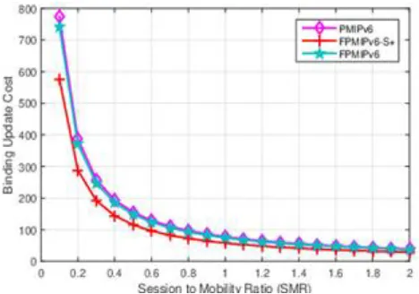
Figure 4 presents the variation of signaling cost on dependency on the session mobility ratio (SMR) for handovers within one LMD domain. For all protocols, signaling cost decreases with the increase of SMR. Indeed, a small value of SMR. Indeed, a small value of SMR indicates a high mobility (i.e. MN changes its attachment point) which will increases the number of signaling messages and then the frequent location updates. As we can see from this figure, FPMIPv6-S+ performs the best of all protocols. This is due to the fact of protocol properties. Indeed, with PMIPv6 or FPMIPv6, if we have n body sensors, every one must sends its own signaling messages to its attachment point. However, with our proposed scheme, only coordinator has the responsibility to send signaling messages. Accordingly, we reduce n-1 times of messages exchanged.
Figure 4: Binding Update Cost Vs SMR
Figure 5 presents the packet delivery costs of three protocols according to the packet arrival rate. From the figure, we can see that the packet transmission cost linearly increases as the packet arrival rate increases for the three protocols. As aforementioned, the packet delivery cost includes the transmission and processing cost to route a tunneled packet from the home agent to the serving foreign agent of an MN. Overall, our proposed scheme results in the lowest packet delivery cost compared to PMIPv6 and FPMIPv6. These results are expected given that FPMIPv6-S+ tries to reduce the signaling messages and provides a tunnel to minimize the
packet loss during the handover. This is able to confirm that our scheme is suitable for real-time applications such as E-health field.
Figure 5: Packet Delivery Cost Vs 𝜆
Figure 6 shows the total costs incurred in PMIPv6, FPMIPv6, and FPMIPv6-S+. Cost in FPMIPv6-S+ is the lowest in the three schemes because, during the handover process, packets from the CN are tunneled and buffered on the n-SMAG.
3695
6
CONCLUSION
In this paper, we have introduced a new fast PMIPv6 handover procedure that supports SDN orchestration and 6LoWPAN protocol. Compared with other previously developed IPv6-based mobility management approaches, proposed 6LoWPAN-based mobility protocol offers a quick and packet-loss free handovers. We have analyze and compare our proposed scheme with PMIPV6 and FPMIPv6 protocols in terms of binding cost, packet delivery cost, and L2 Triggering Time. Numerical results show that FPMIPv6-S+ outperforms PMIPv6 and FPMIPv6 in the case of very high mobility MNs. Accordingly, our proposed scheme results in the lowest packet delivery cost compared to other protocols. Hence, due to their low cost, tiny size, very limited resources (processing, memory, power), minimize the number of signaling packets is necessary for optimized handover performance. In addition, results show that FPMIPv6-S+ has minimum handover latency for smaller values of L2 triggering.
REFERENCES
[1] A. Berguiga and H. Youssef, ―A fast handover protocol for 6lowpan wireless mobile sensor networks,‖ Telecommunication Systems, vol. 68, pp. 163–182, Jun 2018.
[2] M. Bouaziz and A. Rachedi, ―A survey on mobility management protocols in wireless sensor networks based on 6lowpan technol- ogy,‖ Computer Communications, vol. 74, pp. 3 – 15, 2016. Current and Future Architectures, Protocols, and Services for the Internet of Things.
[3] A. Kitana, I. Traore, and I. Woungang, ―Impact study of a mobile
botnet over lte networks.,‖ J. Internet Serv. Inf. Secur., vol. 6, no. 2, pp. 1–22, 2016.
[4] P. Li, J. Li, Z. Huang, C.-Z. Gao, W.-B. Chen, and K. Chen, ―Privacy-preserving outsourced classification in cloud comput- ing,‖ Cluster Computing, vol. 21, no. 1, pp. 277–286, 2018.
[5] Z. Huang, S. Liu, X. Mao, K. Chen, and J. Li, ―Insight of the protection for data security under selective opening attacks,‖ Information Sciences, vol. 412, pp. 223–241, 2017.
[6] R. A. Khan and A. Mir, ―A simulation based study of ip mobility over ipv6 networks,‖ in 2014 Innovative Applications of Computa- tional Intelligence on Power, Energy and Controls with their impact on Humanity (CIPECH), pp. 196–201, IEEE, 2014.
[7] S. Gundavelli, K. Leung, V. Devarapalli, K. Chowdhury, and
B. Patil, ―Rfc 5213: Proxy mobile ipv6,‖ IETF, Aug, 2008.
[8] P. Rost, C. Mannweiler, D. S. Michalopoulos, C. Sartori, V. Scian- calepore, N. Sastry, O. Holland, S. Tayade, B. Han, D. Bega, et al., ―Network slicing to enable scalability and flexibility in 5g mobile networks,‖ IEEE Communications magazine, vol. 55, no. 5, pp. 72– 79, 2017.
[9] A. Berguiga, A. Harchay, A. Massaoudi, and H. Youssef,
―Fpmipv6-s: A new network-based mobility
management scheme for 6lowpan,‖ Internet of Things, p. 100045, 2019.
[10] C. Perkins, D. Johnson, J. Arkko, et al., ―Rfc 6275:
mobility support in ipv6,‖ Internet Engineering Task Force (IETF), 2011.
[11] H. Soliman, L. Bellier, and K. E. Malki, ―Hierarchical mobile ipv6 mobility management (hmipv6),‖ 2005.
[12] A. Huttunen, B. Swander, V. Volpe, L. DiBurro, and M. Stenberg, ―Udp encapsulation of ipsec esp packets,‖ Internet Engineering Task Force, RFC, vol. 3948, 2005.
[13] V. Devarapalli, R. Wakikawa, A. Petrescu, and P. Thubert, ―Net- work mobility (nemo) basic support protocol,‖ 2005.
[14] A. Alsaffar, M. Aazam, C. S. Hong, and E.-N. Huh, ―An architec- ture of iptv service based on pvr-micro data center and pmipv6 in cloud computing,‖ Multimedia Tools and Applications, vol. 76, no. 20, pp. 21579– 21612, 2017.
[15] M. I. Sanchez, M. Uruena, A. De La Oliva, J. A. Hernandez, and
C. J. Bernardos, ―On providing mobility management in wobans: Integration with pmipv6 and mih,‖ IEEE Communications Maga- zine, vol. 51, no. 10, pp. 172– 181, 2013.
[16] M. K. Murtadha, N. K. Noordin, and B. M. Ali, ―Survey and analysis of integrating pmipv6 and mih mobility management approaches for heterogeneous wireless networks,‖ Wireless Per- sonal Communications, vol. 82, no. 3, pp. 1351–1376, 2015.
[17] M.-S. Chiang, C.-M. Huang, P. B. Chau, S. Xu, H. Zhou, and
D. Ren, ―A forward fast media independent handover con- trol scheme for proxy mobile ipv6 (ffmih-pmipv6) over hetero- geneous wireless mobile network,‖ Telecommunication Systems, vol. 65, no. 4, pp. 699– 715, 2017.
[18] H. Alves, L. M. Silva, R. N. Marinheiro, and J. A. R. Moura, ―Pmipv6 integrated with mih for flow mobility management: A real testbed with simultaneous multi-access in heterogeneous mobile networks,‖ Wireless Personal Communications, vol. 98, no. 1, pp. 1055– 1082, 2018.
[19] C.-M. Huang, M.-S. Chiang, D.-T. Dao, and B.-C. Pham, ―A group-based fast media independent handover control scheme for proxy mobile ipv6 (gb-fmih-pmipv6),‖ in 2016 IEEE Inter- national Black Sea Conference on Communications and Networking (BlackSeaCom), pp. 1–5, IEEE, 2016.
[20] J. Guan, I. You, C. Xu, and H. Zhang, ―The pmipv6-based group binding update for iot devices,‖ Mobile Information Systems, vol. 2016, 2016.
[21] A. Michalas, A. Sgora, and D. D. Vergados, ―An integrated mih- fpmipv6 mobility management approach for evolved-packet sys- tem architectures,‖ Journal of Network and Computer Applications, vol. 91, pp. 104– 119, 2017.
[22] L. Zhang and Y.-C. Tian, ―An enhanced fast handover triggering mechanism for fast proxy mobile ipv6,‖ Wireless Networks, vol. 24, no. 2, pp. 513–522, 2018.
[23] M. Balfaqih, M. Ismail, R. Nordin, and Z. A. Balfaqih, ―802.21- assisted distributed mobility management solution in vehicular networks,‖ IEEE Access, vol. 5, pp. 9518–9532, 2017.
3696
96, no. 2, pp. 1653–1672, 2017.
[25] A. Berguiga and H. Youssef, ―A fast handover protocol for 6lowpan wireless mobile sensor networks,‖ Telecommunication Systems, vol. 68, no. 2, pp. 163– 182, 2018.
[26] M. M. Islam, ―Sensor proxy mobile ipv6: A novel scheme for mobility-supported ip-wsn,‖ Emerging Communication Technolo- gies Based on Wireless Sensor Networks: Current Research and Future Applications, p. 359, 2016.
[27] A. J. Jabir, S. K. Subramaniam, Z. Z. Ahmad, and N. A. W. A. Hamid, ―A cluster-based proxy mobile ipv6 for ip-wsns,‖ EURASIP Journal on Wireless Communications and networking, vol. 2012, no. 1, p. 173, 2012.
[28] S. Ro and V. H. Nguyen, ―Inter-domain mobility support in proxy mobile ipv6 using overlap function of mobile access gateway,‖ Wireless Networks, vol. 21, no. 3, pp. 899–910, 2015.
[29] M. Ha, S. H. Kim, and D. Kim, ―Intra-mario: A fast mobility management protocol for 6lowpan,‖ IEEE Transactions on Mobile Computing, vol. 16, no. 1, pp. 172–184, 2016.
[30] M. Bouaziz, A. Rachedi, and A. Belghith, ―Ec-mrpl: An energy- efficient and mobility support routing protocol for internet of mobile things,‖ in 2017 14th IEEE Annual Consumer Communica- tions Networking Conference (CCNC), pp. 19–24, Jan 2017.
[31] F. Somaa, I. El Korbi, C. Adjih, and L. A. Saidane, ―A modified rpl for wireless sensor networks with bayesian inference mobil- ity prediction,‖ in 2016 international wireless communications and mobile computing conference (IWCMC), pp. 690–695, IEEE, 2016.
[32] S. Sanshi and C. Jaidhar, ―Enhanced mobility routing protocol for wireless sensor network,‖ Wireless Networks, pp. 1–15, 2018.
[33] M. Bouaziz, A. Rachedi, and A. Belghith, ―Ekf-mrpl: Advanced mobility support routing protocol for internet of mobile things: Movement prediction approach,‖ Future Generation Computer Sys- tems, 2017.
[34] J. Park, K.-H. Kim, and K. Kim, ―An algorithm for timely transmission of solicitation messages in rpl for energy-efficient node mobility,‖ Sensors, vol. 17, no. 4, p. 899, 2017.
[35] W. Xiaonan and C. Hongbin, ―Research on seamless mobility han- dover for 6lowpan wireless sensor networks,‖ Telecommunication Systems, vol. 61, pp. 141–157, Jan 2016.
[36] S. Bailey, D. Bansal, L. Dunbar, D. Hood, Z. L. Kis, B. MackCrane,
J. Maguire, D. Malek, D. Meyer, M. Paul, et al., ―Sdn architecture overview,‖ Open Networking Foundation, Ver, vol. 1, 2013.
[37] C. Makaya and S. Pierre, ―An analytical framework for per- formance evaluation of ipv6-based mobility management proto- cols,‖ IEEE Transactions on wireless communications, vol. 7, no. 3, pp. 972–983, 2008.
[38] S. Pack and Y. Choi, ―A study on performance of hierarchical mobile ipv6 in ip-based cellular networks,‖ IEICE transactions on communications, vol. 87, no. 3, pp. 462–469, 2004.
[39] L. J. Zhang and S. Pierre, ―Evaluating the performance of fast handover for hierarchical mipv6 in cellular
networks,‖ Journal of Networks, vol. 3, no. 6, pp. 36– 43, 2008.
[40] A. Berguiga and H. Youssef, ―Efficient mobility management in 6lowpan wireless sensor networks,‖ in Proceedings of the ninth international conference on wireless and mobile communications (ICWMC 2013), Nice, France, vol. 2126, pp. 244–250, 2013.