Dynamic Voltage Restorer Based on Space
Vector Pulse Width Modulation Technique
B.N S P Venkatesh* D.Prathap Hari Krishna
PG Student, EEE department, Gitam University, PG Student, EEE department, Gitam University, Visakhapatnam, Andhra Pradesh, 533045, India. Visakhapatnam, Andhra Pradesh, 533045, India.
[email protected] [email protected]
* Corresponding Author
G.Sai Sudheer S.Rishikesh
PG Student, EEE department, Gitam University, PG Student, EEE department, Gitam University, Visakhapatnam, Andhra Pradesh, 533045, India. Visakhapatnam, Andhra Pradesh, 533045, India.
[email protected] [email protected]
Abstract:
Power Quality problems encompass a wide range of disturbances such as voltage sags, swells, flicker, harmonics distortion and interruptions. The strategic deployment of custom power devices has been proposed as one of the means to protect sensitive loads from power quality problems such as voltage sags and swells. The Dynamic Voltage Restorer (DVR) is a power electronic device that is used to inject 3-phase voltage in series and in synchronism with the distribution feeder voltages in order to compensate voltage sag and similarly it reacts quickly to inject the appropriate voltage component (negative voltage magnitude) in order to compensate voltage swell. The principal component of the DVR is a voltage source inverter that generates three phase voltages and provides the voltage support to a sensitive load during voltage sags and swells. Pulse Width Modulation Technique is very critical for proper control of DVR. Sinusoidal Pulse Width Modulation (SPWM) and Space Vector Pulse Width Modulation (SVPWM) control techniques are used for controlling the DVR. In this work, the operation of DVR is presented and the control technique used for voltage source inverter is Space Vector PWM technique. Space vector PWM can utilize the better dc voltage and generates the fewer harmonic in inverter output voltage than Sinusoidal PWM technique. This work describes the DVR based on Space Vector PWM which provides voltage support to sensitive loads and is simulated by using MATLAB/SIMULINK. Simulation results show that the control approach is able to compensate for any type of voltage sags and swells.
Keywords: Dynamic Voltage Restorer (DVR), Sinusoidal Pulse Width Modulation Technique (SPWM), Space Vector Pulse Width Modulation Technique (SVPWM).
1. Introduction
as an increase to between 1.1p.u and 1.8p.u in rms voltage or current at the power frequency durations from 0.5 to 1 minute [3]. A swell can occur due to a single line-to-ground fault on the system, which can also results in temporary voltage rise on the unfaulted phases. This is especially true in ungrounded or floating ground delta systems, where the sudden change in ground reference result in a voltage rise on the ungrounded phases. On an ungrounded system, the line-to ground voltages on the ungrounded phases will be 1.73p.u during a fault condition. Swells can also be generated by sudden load decreases and switching on a large capacitor bank often causes an oscillatory transient.. To solve this problem, custom power devices are used. One of those devices is the Dynamic Voltage Restorer (DVR), which is the most efficient and effective modern custom power device used in power distribution networks. Its appeal includes lower cost, smaller size, and its fast dynamic response to the disturbance. The Dynamic Voltage Restorer (DVR) is a power electronic device that is used to inject 3-phase voltage in series and in synchronism with the distribution feeder voltages in order to compensate for voltage sag [4] and similarly it reacts quickly to inject the appropriate voltage component (negative voltage magnitude) in order to compensate voltage swell. In this work, voltage sag and swell is compensated using DVR based on Space Vector Pulse Width Modulation technique (SVPWM). It is found that DVR based on Space Vector PWM technique (SVPWM) compensates voltage sags and swells effectively compare to Sinusoidal Pulse Width Modulation technique (SPWM).
2. Dynamic Voltage Restorer
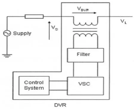
DVR is a series connected custom power device. Its main function is the protection of sensitive loads from any voltage disturbances except voltage outage. It is basically consists of power circuit and control circuit. The power circuit of the DVR has four main parts; voltage source inverter (VSI), voltage injection transformer, DC energy storage device and low pass filter [4], [5] as shown in Fig. 1.
Figure 1: Power Circuit of DVR
A. Voltage Source Inverter (VSI)
VSI is used to convert the DC voltage supplied by the energy storage device to an AC voltage. This voltage is boosted through injection transformer to the main system. Usually the rating of the VSI is low voltage and high current due to the use of step up injection transformers.
B. Voltage Injection Transformer
C. DC energy storage device
It provides the real power requirement of the DVR during compensation. Lead-acid batteries, Flywheels, Super conducting Magnetic Energy Storage (SMES) and Super capacitors can be used as the storage devices. For Batteries and SMES, DC to AC conversion (inverters) is necessary, while for flywheels AC to AC conversion is required [5].
D. Passive Filter
A passive low pass filter consists of an inductor and a capacitor. It can be placed either at the high voltage side or the inverter side of the injection transformer. It is used to filter out the switching harmonic components from the injected voltage. By placing the filter at the inverter side, the higher order harmonics are prevented from penetrating into transformer, thereby it reduce the voltage stress on the injection transformer. When the filter is placed on the high voltage side, since harmonics can penetrate into the high voltage side of the transformer, a higher rating transformer is required [4], [5].
3. Calculation of Voltage Injection by DVR
The schematic diagram of a typical DVR is shown in Fig (2). The circuit left hand side of the DVR represents the thevenin equivalent circuit of the system. The system impedance (Zth = Rth + jXth) depends on the fault level
of the load bus. When the system voltage (Vth) drops, the DVR injects a series voltage VDVR through the
injection transformer so that the desired load voltage magnitude VL can be maintained.
Consider the schematic diagram shown in the fig (2)
By using KVL
Vth - Zth IL + VDVR = VL (1)
VDVR + Vth = VL + Zth IL (2)
Therefore, the series injected voltage of the DVR can be written as VDVR = VL + Zth IL - Vth (3)
Here,
Vth = system supply voltage (Thevenin voltage)
VL= load bus voltage
Zth = system impedance (Thevenin impedance)
IL = load current and
*
L L L LV
JQ
P
I
(4)When VL is considered as a reference, equation (3) can be rewritten as
VDVRסα =VLס 00+Zth ILסβ- Ф-Vthסδ (5)
Here α, β and δ are the angles of VDVR, Zth and Vth respectively and Ф is the load power factor angle
with
L LP
Q
1tan
Figure 2: Schematic Diagram of a DVR
The complex power injection by the DVR can be written as
SDVR = VDVR IL* (7)
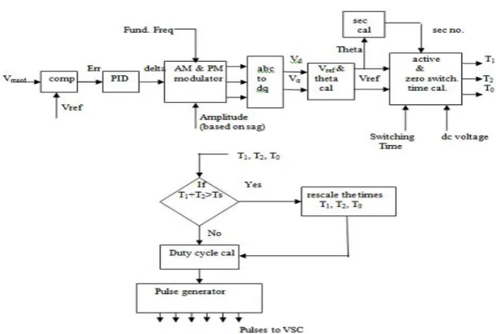
4. DVR Control System
The main aim of the control system is to maintain the constant voltage magnitude at the point where a sensitive load is connected, under system disturbances.
Figure 4: Sinusoidal PWM-based control system
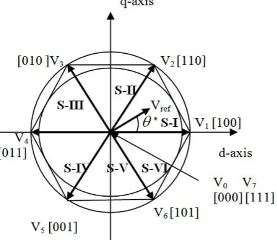
The active and zero switching time for a particular sector are calculated by using the following formulae
3
sin
.
.
.
3
1n
V
V
T
T
dc ref z (8)
3
1
sin
.
.
.
3
2n
V
V
T
T
dc ref z (9))
(
1 20
T
T
T
T
z
(10)Where n=1 through 6, i.e. sector 1 to 6 and
0
60
0Figure 5: Space Vector PWM based Control Systems
2 1 2 1T
T
T
T
T
T
T
S b a (11)So that Ta+Tb=Ts and T0 = 0. According to this rescaling process, the converter can operate up to the modulation
index 0.952. From the equations (8)-(11) duty cycles can be calculated as
3
sin
.
..
3
1 1n
V
V
d
T
orT
T
dc ref S a (12)
3
1
sin
.
.
3
2 2n
V
V
d
T
orT
T
dc ref S b (13)These duty cycles are symmetrically distributed corresponding to each sector. By this symmetrical distribution, only one phase is changing to on or off during the changing of adjacent state vector and hence switching losses will be reduced.
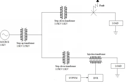
5. Simulation Results
The single line diagram of system considered for study is shown in figure 6 which is simulated using MATLAB/SIMULINK 7.8 version comprised by a 13KV, 50HZ source supplies to bus where a load is connected. To analyze the working of DVR for voltage sag and voltage swell compensation a fault is applied to the system for time duration of 200ms.The DVR is simulated to be in operation only for the duration of fault.
Voltage sag occurred due to three phase short circuit
The system considered for study is simulated with no DVR and three phase fault is applied to the system resulting in 50% sag for time duration of 200ms. The second simulation is carried to with the same scenario as above but now a DVR is now introduced at the load side to compensate the voltage sag occurred due to the fault applied. Figure 7 shows the load voltage when the system operates without DVR and with DVR using Sinusoidal PWM technique and figure 8 shows the load voltage without DVR and with DVR using Space Vector PWM technique when a three phase fault is applied to the system.
Figure 7 Load voltage without DVR and with DVR for three phase short circuit using Sinusoidal PWM technique
Figure 8 Load voltage without DVR and with DVR for three phase short circuit using Space Vector PWM technique
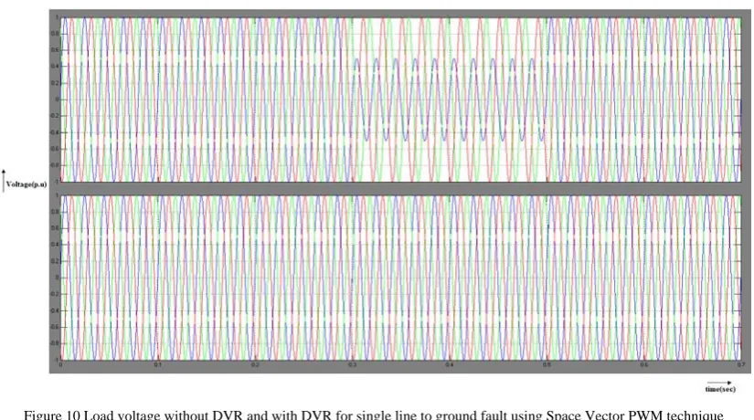
Voltage Sag occurred due to Single line to ground fault
now introduced at the load side to compensate the voltage sag occurred. Figure 10 shows the load voltage when the system operates without DVR and with DVR using Sinusoidal PWM technique and figure 11 shows the load voltage without DVR and with DVR using Space Vector PWM technique when a single line to ground fault is applied to the system.
Figure 9 Load voltage without DVR and with DVR for single line to ground fault using Sinusoidal PWM technique
Figure 10 Load voltage without DVR and with DVR for single line to ground fault using Space Vector PWM technique
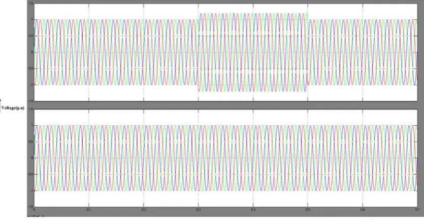
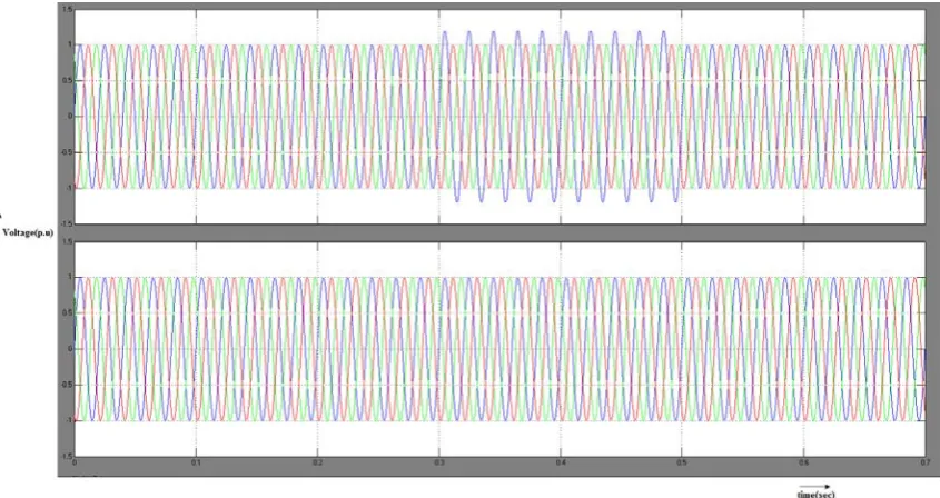
Voltage swell occurred due to three phase fault
voltage without DVR and with DVR using Space Vector PWM technique when a three phase swell is created in the system.
Figure 11 Load voltage without DVR and with DVR for three phase swell using Sinusoidal PWM technique
Figure 12 Load voltage without DVR and with DVR for three phase swell using Space Vector PWM technique
Voltage swell occurred due to single line to ground fault
voltage without DVR and with DVR using Space Vector PWM technique when a single phase swell is created in the system.
Figure 13 Load voltage without DVR and with DVR for single phase swells using Sinusoidal PWM technique
Figure 14 Load voltage without DVR and with DVR for single phase swell using Space Vector PWM technique The above figures clearly show the performance of Dynamic Voltage Restorer (DVR) based on Sinusoidal Pulse Width Modulation (SPWM) and Space Vector Pulse Width Modulation (SVPWM) and the results are tabulated as follows.
Table 1 Comparison between Voltage magnitudes in p.u due to voltage sag with DVR using SPWM & SVPWM
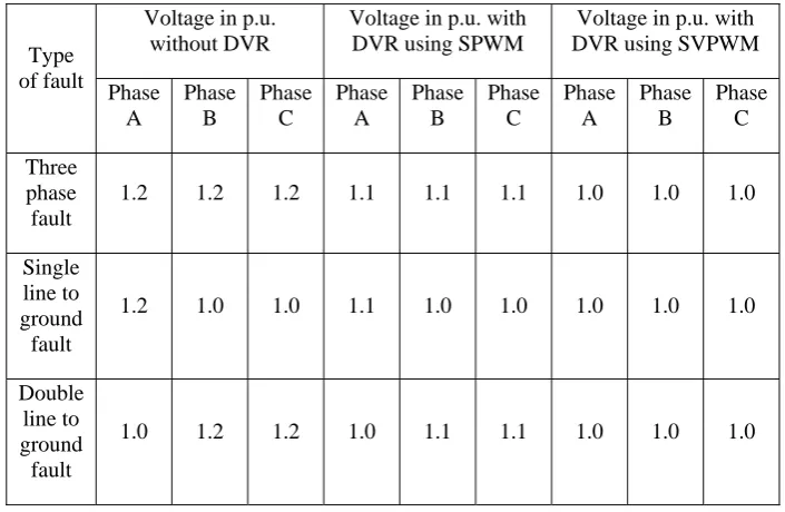
Comparison between Voltage magnitudes in p.u due to voltage swell with DVR using SPWM & SVPWM
Table 2 Comparison between voltage magnitude in p.u due to voltage swell with DVR using SPWM and SVPWM .
6. Conclusion
This paper presented the performance of Dynamic Voltage Restorer against voltage sags and swells using Space vector Pulse Width Modulation (SVPWM) technique through MATLAB/SIMULINK software. The results of space vector PWM technique are compared with the results of sinusoidal PWM technique. Sinusoidal PWM technique results in a voltage magnitude of 1.06 p.u. whereas Space Vector PWM technique results in a voltage magnitude of 1.0 p.u. In both the voltage sag and voltage swell cases, Space vector PWM technique effectively restored the critical load voltage when compared with sinusoidal PWM. The main advantage of this DVR is low cost and its control is simple. It can mitigate long duration voltage sags and swells efficiently.
Type of fault
Voltage in p.u. without DVR
Voltage in p.u. with DVR using SPWM
Voltage in p.u. with DVR using SVPWM Phase A Phase B Phase C Phase A Phase B Phase C Phase A Phase B Phase C Three phase fault
0.5 0.5 0.5 1.06 1.06 1.06 1.0 1.0 1.0
Single line to ground fault
0.5 1.0 1.0 1.06 1.0 1.0 1.0 1.0 1.0
Double line to ground fault
1.0 0.5 0.5 1.0 1.06 1.06 1.0 1.0 1.0
Type of fault
Voltage in p.u. without DVR
Voltage in p.u. with DVR using SPWM
Voltage in p.u. with DVR using SVPWM
Phase A Phase B Phase C Phase A Phase B Phase C Phase A Phase B Phase C Three phase fault
1.2 1.2 1.2 1.1 1.1 1.1 1.0 1.0 1.0
Single line to ground fault
1.2 1.0 1.0 1.1 1.0 1.0 1.0 1.0 1.0
Double line to ground fault
REFERENCES
[1] Shairul Wizmar Wahab and Alias Mohd Yusof, “Voltage Sag and Mitigation Using Dynamic Voltage Restorer (DVR) System”, electrika, vol.8, No.2, pp. 32-37, 2006.
[2] IEEE recommended practice for evaluating electric power system compatibility with electronic process equipment, IEEE Standard 1346-1998. 1998.
[3] Electrical Power Systems Quality by ROGER C. DUNGAN
[4] Agileswari K. Ramasamy, Rengan Krishnan Iyer, Dr. Vigna K Ramachandaramurthy, Dr. R.N.Mukerjee, “Dynamic Voltage Restorer for Voltage sag compensation”, IEEE PEDS 2005, pp. 1289-1294.
[5] Ghosh and G. Ledwich , “ Power quality Enhancement using custom power devices” Kluwer Academic publishers,2002 .
[6] J. Arrilliga, N.R. Watson and S. Chen, Power Quality Assessment, John Wiley, NewYork, 2000.
[7] J. Lamoree, D. Muller, P. Vinnett, W. Jones, "Voltage Sag Analysis Case Studies", IEEE Transactions on Industry Applications, Volume: 30, Issue: 4, July-Aug. 1994, pp. 1083 -1089.
[8] FACTS Controllers in power transmission and distribution by K.R.PADIYAR.
[9] C. Zhan, V.K. Ramachandaramurthy, A. Arulampalam, C. Fitzer, S Kromlidis, M. Barnes, N. Jenkins, "Dynamic voltage restorer based on voltage space vector PWM control" in Proc. 2001 Applied Power Electronics Conference and Exposition, pp. 1301- 1307. [10] V.K. Ramachandaramurthy, C. Fitzer, A. Arulampalam, C. Zhan, M.Barnes, N. Jenkins “Control of a battery supported dynamic
voltage restorer” in Proc. 2002 IEE Generation, Transmission and Distribution, Volume 149, Issue 5, pp. 533 – 542.