REALIZATION OF
MULTIPLE-OPERAND ADDER-SUBTRACTOR
BASED ON VEDIC MATHEMATICS
NEETA PANDEY1, RAJESHWARI PANDEY2, SAMIKSHA AGARWAL3, PRINCE KUMAR4
Department of Electronics and Communication Engineering Delhi Technological University
Bawana Road, Delhi-110042
1
[email protected], [email protected], [email protected],
4
ABSTRACT
This paper presents multiple-operand adder-subtractor based on Nikhilam Sutra of Vedic mathematics. The Sutra is adapted for binary operands. The hardware implementation uses carry save adders and a new 2’s exponent subtractor for faster operation and hardware reduction. The suitability of the theoretical proposition is demonstrated through exhaustive examples. The functionality of the circuit is verified through VHDL simulations. The synthesis results and comparisons with conventional methods are also included.
Keywords -- Vedic Maths, High-speed Multi-operand Adder-Subtractor, Nikhilam Sutra, Carry save adder, VHDL.
1. Introduction
Vedic Mathematics is the name given to the ancient system of Indian Mathematics which was rediscovered from the Vedas (ancient Indian sculptures) between 1911 and 1918 by Sri Bharati Krishna Tirthaji. Vedic Mathematics consists of sixteen sutras, and manifests the coherent and unified structure of mathematics using complementary, direct and easy methods. The algorithms based on conventional mathematics can easily be simplified and even optimized by the use of Vedic Mathematics [1-7].
This paper addresses the problem of multi-operand addition-subtraction illustrated through following operation: (149 - 43- 19 – 63). The conventional method to solve this kind of problem is to first subtract 43 from 149 resulting in 106. The number 19 is subtracted next providing result as 87. Finally, 63 is subtracted out, yielding 24. Thus, depending on the number of operands, this process continues until no operand is left, which is very cumbersome and time-consuming.
This led us to develop multi-operand adder-subtractor employing Nikhilam Sutra of Vedic Mathematics. According to the sutra, all the numbers to be subtracted are replaced by their 10's complements. Then, all the resulting new operands are added up together, following which, all the powers of 10, with respect to which the 10's complements were taken, are subtracted out. For hardware implementation, numbers are represented in binary. Therefore 2's complements is employed instead of 10's complements, followed by subtracting out the powers of 2 in the last step, where the exponent of 2 is the number of bits used to represent the binary number. However, in the two’s complement binary number representation of the proposed approach, the sign bit is treated separately. Also, Carry-Save adder [6] is used, which being a multiple-operand adder provides faster addition than the conventional 2-operand adder.
2. Multi-operand adder subtractor using Nikhilam-Sutra 2.1 Nikhilam Sutra
Nikhilam Sutra is one of the sutras of Vedic Mathematics which means ‘All from 9 and last from 10’. It stipulates subtraction of a number from the nearest power of 10 like 10, 100, 1000 etc. The powers of 10 from which the difference is calculated is called the Base. If the given number is 104, the nearest power of 10 is 100 and is the base. Hence the difference between the base and the number is 4 and it is called NIKHILAM.
2.2 Decimal Number Implementation
This subsection describes the use of Nikhilam Sutra for performing the addition-subtraction of multiple decimal numbers. It has been explained by taking two cases, as shown in Table I.
Table I. Nikhilam Sutra in Decimal Numbers
CASE 1 CASE 2
Becomes
(10’s complement of 62 with respect to 100)
(10’s complement of 59 with respect to 100)
216
Since 10’s complement for two operands have been taken, we need to subtract the base that is 100, twice from the answer. The answer is greater than 200, so subtracting out 100 twice gives us 16 right away, which is the final answer.
Becomes
(10’s complement of 74 with respect to 100)
(10’s complement of 63 with respect to 100)
184
This answer is less than the 200 that we need to subtract. So, we first subtract 100 from it to get 84. Then, 10’s complement of 84 with respect to the second 100 is 16.
Thus, final answer is -16.
2.3 Binary Number Implementation
For hardware implementation, numbers are represented in binary and Nikhilam Sutra has been adapted for binary number system. In the proposed approach, the 2's complements are employed instead of 10's complements followed by subtracting out the powers of 2, where the exponent of 2 is the number of bits used to represent the binary number.
To elaborate the scheme, three k-bit binary numbers are taken. Let us calculate P = a–b–c
The operands to be subtracted can be represented in their 2’s complements form as
b = – b’
c = –c’
Thus,
P = a – ( – b’) – ( - c’)
P = a + b’ + c’ – (2. ) (1)
Thus, the problem of complex subtraction is reduced to simple addition, followed by subtraction of powers of two in binary, as shown in Equation (1).
2.4 Proposed Architecture
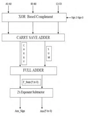
Considering three 4-bit binary operands, the proposed architecture is given in Figure 1. Here, the inputs are three 4- bit binary numbers (A3-A0, B3-B0, C3-C0). Sign2, Sign1and Sign0 are the sign bits of a, b and c respectively. If sign bit = ‘0’, the operand is to be added and if sign bit=‘1’, the operand is to be subtracted.
Figure 1. Block Diagram of Multiple-Operand Adder-Subtractor using Nikhilam Sutra
The block diagram in Figure 1 is explained using the following steps:
Step 1: The binary operands along with their signs are fed to the ‘XOR based Complement’ block, which produces the complemented outputs (2’s complements) of the operands to be subtracted.
Step 3: The two outputs of Carry Save Adder, that is, SUM and CARRY are fed as inputs to the Full Adder, which gives the result F_sum, a 6-bit binary number. F_sum is represented in 6-bits as a maximum of 6 bits are needed to represent the result of addition of three 4 bit binary numbers.
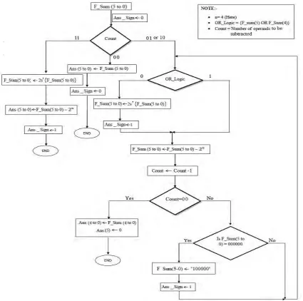
Step 4: The output of step 3 is fed to ‘2’s exponent Subtractor’ block. Its function is to subtract out the powers of 2 in binary, where the exponent of 2 is the number of bits used to represent the operand. This block provides the final answer in the sign-magnitude form. The least significant 6 bits of the answer represents the magnitude and the seventh bit represents the sign of the final answer. The flowchart of the 2’s exponent Subtractor is shown in Figure 2.
Figure 2. Algorithmic Flowchart of 2’s Exponent Subtractor
It can be noted from the flowchart in Figure 2 that several cases can arise while performing addition-subtraction of multiple binary numbers. These cases can be mathematically proved as follows:
Case 1: When all the operands are positive (sign=000), that is (a+b+c) is to be calculated. F_Sum (5-0) = (a+b+c)
Thus,
Ans (5-0) = F_Sum(5-0) Ans_sign = 0
be calculated (sign=001). F_Sum (5-0) = {a+b+ ( –c)}
Two possibilities arise here:
i. c < (a+b) (i.e. Answer is going to be positive) Thus,
Ans (5-0) = F_Sum (5-0) –
Ans_sign = 0
ii. c > (a+b) (i.e. Answer is going to be negative) Thus,
Ans(5-0) = { 2s ‘{F_Sum(5-0)} – }
Ans_sign=1 Explanation:
Let G_Sum(5-0) = 2s’ {F_Sum(5-0)} = –F_Sum(5-0)
= 4. – F_Sum(5-0)
= 4. – {a+b+ ( –c)}
= 3. – {a+b–c}
Now,
Ans(50) = G_Sum(50)
= 3. – {a+b–c)–
= 2. – (a+b–c)
At first, this seems incorrect because the desired answer is (a+b–c). However, careful examination reveals that subtracting 2.2n from (a+b–c) is equivalent to considering the 5 least significant bits of the answer and ignoring the 6th bit. Therefore, the above expression is same as the desired answer, but with the 6th bit ignored and the sign as negative. Thus Ans(4-0)= Ans(4 to 0) and Ans(5)=0, along with Ans_sign=1.
Case 3: When two of the operands are negative and one is positive (sign= 011or 101 or 110). Let (a–b–c) is to be calculated (sign=011).
F_Sum(5-0) = {a+( –b)+( –c)}
= {2. + (a–b–c)} Four possible cases arise here:
i. (b+c) < a (i.e. Answer is going to be positive) Thus,
Ans(5-0) = F_Sum(5-0) – 2.
Ans_sign = 0
ii. (b+c) > a (i.e. Answer is going to be negative, but greater than in magnitude, which implies that
F_Sum(5-0) is lesser than in magnitude) Thus,
Ans(5-0) = 2s’{F_Sum(5-0)} –
Ans_sign = 1
iii. (b+c) > a (i.e. Answer is going to be negative, but lesser than in magnitude, which implies that
F_Sum(5-0) is greater than in magnitude, but lesser than 2. )
Let, G_Sum(5-0) = F_Sum(5-0) – Then,
Ans (5-0) = 2s’{G_Sum(5-0)} – Ans_sign = 1
Explanation:
= {2. + (a–b–c)} –
= + (a–b–c)
Now,
Ans(5-0) = 2s’{G_Sum(5-0)} –
= { – G_Sum(5-0)}–
= {4. – G_Sum(5-0)} –
= {3. – G_Sum(5-0)}
= {3. – { + (a–b–c)}}
= 2. – (a–b–c)
Now, ignoring the 6th bit of the Ans(5 - 0) is equivalent to subtracting 2. from it. Thus Ans(4-0)= Ans (4-0) and Ans(5)=0, making Ans_sign=1.
iv. (b+c) > a (i.e. Answer is going to be negative, but equal to in magnitude)
F_Sum(5-0) = (a–b–c) + 2.
Let G_Sum(5-0) = F_Sum(5-0) –
= (a–b–c) +
Now, value of G_Sum at this stage is zero (i.e. 000000), and taking 2’s complement of it gives a seven bit number. So we neglect the 6th bit, i.e. G_Sum(5), which is zero.
Ans (5-0) = 2s’ {G_Sum (4-0)} –
= {2. – (a–b–c) – } –
= – (a–b–c)
Thus Ans(5-0) gives the magnitude of the result, and Ans_sign = 1.
Case 4: When all the operands are negative (sign= 111), that is (–a–b–c) is to be calculated.
F_Sum (5-0) = {( –a) + ( –b) + ( –c)}
= 3. – (a+b+c)
Thus,
Ans (5-0) = 2s’ {F_Sum( 5 - 0 )} – Ans_sign = 1
Explanation:
Let G_Sum(5 - 0) = 2s’{ F_Sum(5 - 0) } = – F_Sum( 5 - 0)
= 4. – F_Sum(5 - 0)
= 4. – {3. – (a+b+c)}
= – (–a –b –c) Now,
Ans(5 – 0) = G_Sum(5 - 0) –
= – (–a –b –c) – = – (–a –b –c)
Thus the Ans(5-0) gives the magnitude of the sum, and the negative sign shows that Ans_sign =1.
3. Functional Verification and Synthesis Results
The algorithm of this paper was simulated and the functionality was examined using an Integrated Software Environment (ISE) [8]. The proposal is also implemented on FPGA (Field Programmable Gate Array) device [9]. In the design-entry stage, the VHDL code for the proposed algorithm was written, which was checked for errors. The code was then synthesized using the synthesis tool [10] of the ISE. For simulation of the proposed multi-operand adder-subtractor using Nikhilam Sutra, the Simulation tool [11] of the ISE was used.
3.1 Simulation Results
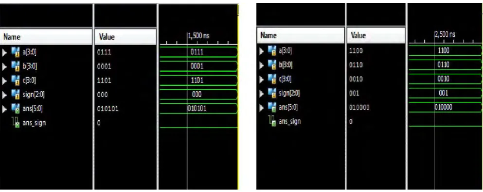
To demonstrate the operation of the proposed algorithm, the following four cases are considered. 1. When all the operands are positive(sign=000):
Let a=7, b= 1, c=13 Then, a+b+c= 21
2. When one operand is negative and two are positive(sign=001): Let a=12, b=6, c=2
Then, a+b–c=16
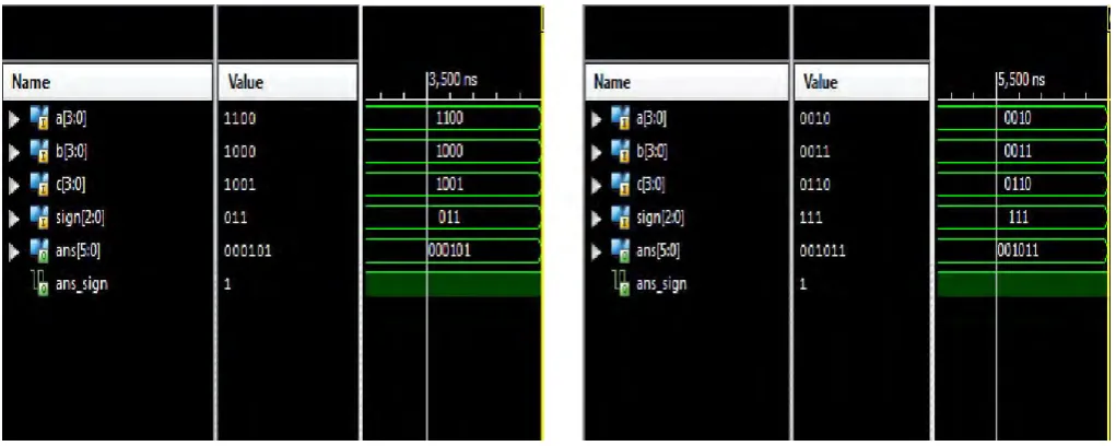
3. When two operands are negative and one is positive(sign=011): Let a=12, b=8, c= 9
Then a–b–c= –5
4. When all the operands are negative(sign=111): Let a=2, b=3, c=6
Then –a–b–c= –11
The simulation results are depicted in Figure 3, Figure 4, Figure 5 and Figure 6 for Cases 1, 2, 3 and 4 respectively.
Figure 5. Simulation results for Case 3 Figure 6. Simulation results for Case 4
3.2 Synthesis Results and Discussions
After functional verification was done, this multi-operand adder-subtractor design based on Nikhilam Sutra was synthesized on the FPGA device [9]. The device utilization summary and timing parameters are shown in Figure 7 and Figure 8 respectively.
Figure 7. Device Utilization Summary
Figure 8. Timing Summary
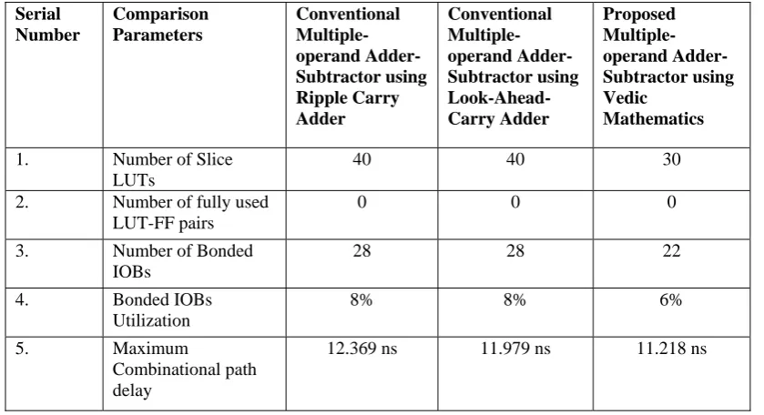
Table II displays the comparison of synthesis results of the proposed multiple-operand adder –
Table II. Comparison of the Proposed method with the Conventional methods
It is observed that for the method proposed using Nikhilam Sutra of Vedic Mathematics, the device utilization (number of slices) is only 30, as compared to 40 for Conventional Multiple-operand Adder-Subtractor using Ripple Carry Adder and Look-Ahead-Carry Adder. The delay of the proposed approach is 11.218 ns, which is considerably less than the time delay of the conventional multiple-operand adder-subtractor using Ripple Carry Adder (12.369 ns) and Look-Ahead-Carry-Adder(11.979 ns). Also, the utilization of bonded IOBs (input-output blocks) in our approach is 22 (6%) as compared to the 28 (8%) bonded IOBs Utilization of the conventional methods for multiple-operand addition-subtraction. This is because in order to avoid bit overflow, extra bits are used to represent the signed binary operands in case of conventional multiple-operand adder-subtractors. This increases the IO utilization and consequently the cost of the hardware. In the proposed approach, there is no need for extra bits to represent the operands in order to handle overflows, thereby reducing the IOs and hence the cost.
4. Conclusion
The adaptation of Nikhilam Sutra to binary multiple operand addition - subtraction is presented in this paper. The workability of the proposition is demonstrated through suitable examples. The functional verification confirms the proposal.
REFERENCES
[1] Tirthaji B.K. ,“Vedic Mathematics”,Delhi, Motilal Banarsidass, 1965.
[2] Kansara N. M., “Vedic Sources of the ‘Vedic Mathematics’, Sambodhi, Vol. XXIII, 2000. [3] Maharaja, J. S. S. B. K. T., “Vedic mathematics”, Delhi, Motilal Banarsidass, 2009.
[4] Chidgupkar, P. D., & Karad, M. T., “The implementation of vedic algorithms in digital signal processing”, Global Journal of Engineering Education, 8, 153–158, 2004.
[5] Parhami, B., Computer arithmetic algorithms and hardware architectures (2nd edition), New York: Oxford University Press. [6] Pradhan M and Panda R., “High speed multiplier using Nikhilam Sutra algorithm of Vedic mathematics”, International Journal of
Electronics, DOI:10.1080/00207217.2013.780298.
[7] Awasthi V. and Gupta T., “A Survey on the Algorithms of Fast Digital Adders”, VSRD International Journal of Electrical, Electronics & Comm. Engg.Vol.1(7), 2011.
[8] Xilinx ISE 14.2(http://www.xilinx.com/products/design-tools/ise-design-suite/index.htm)
[9] Spartan 6 XC6SLX150-3FGG484 (http://www.xilinx.com/support/documentation/data_sheets/ds160.pdf) [10] Xilinx XST (http://www.xilinx.com/tools/xst.htm)
[11] ISE Simulator (ISim) (http://www.xilinx.com/tools/isim.htm)
Serial Number Comparison Parameters Conventional Multiple-operand Adder-Subtractor using Ripple Carry Adder Conventional Multiple-operand Adder-Subtractor using Look-Ahead-Carry Adder Proposed Multiple-operand Adder-Subtractor using Vedic Mathematics
1. Number of Slice
LUTs
40 40 30
2. Number of fully used LUT-FF pairs
0 0 0
3. Number of Bonded
IOBs
28 28 22
4. Bonded IOBs Utilization
8% 8% 6%
5. Maximum Combinational path delay