“ANALYSIS ON PERFORMANCE OF
RADIANT HEAT EXCHANGER OF
THERMIC FLUID HEATER BY
CHANGING THE SUITABLE GRADE OF
MATERIAL”
“Patel Ronak I.1, Tandel Shyamal N.2, Patel Miteshkumar H.3, Patel Jaykumar S.4, MominInayat Husain M.5”
1. UG student 2. UG student 3.UG student 4.UG student 5.UG student of Mechanical engineering Department, Shree Swami AtmanandSaraswati Institute of Technology, Surat-395006
+91-7567694094, [email protected]; +91-9638101863, [email protected]; +91-9824537696, [email protected];
+91-9429986699, [email protected]; +91-7405237847, [email protected]
Abbreviation
GTVA : Gujtex Thermic Vertical Annulus
HP : Horse Power
ASTM : American Society for Testing and Material
BS : British Standards
AISI : American Iron and Steel Industry
TTHE : Tube in Tube helical coil Heat Exchanger
CFD : Computational Fluid Dynamics
PCD : Pitch Circle Diameter (mm)
Str : Short tandem repeat
HHV : Higher Heating Value (kJ/kg or kJ/kmol)
HCV : Higher Calorific Value (kJ/kg or kJ/kmol)
GCV : Gross Calorific Value (kJ/kg or kJ/kmol)
LHV : Lower Heating Value (kJ/kg or kJ/kmol)
LCV : Lower Calorific Value (kJ/kg or kJ/kmol)
NCV : Net Calorific Value (kJ/kg or kJ/kmol)
PMCC : Pensky Martens Closed Cup (0
C
)COC : Cleveland Open Cup (0
C
)DAF : Dry Air Fraction
Nomenclature
Re : Reynolds Number
Nu : Nusselt Number
hi : Convective heat transfer co-efficient for inner side (W/ m20C)
d : Tube diameter (mm)
D : Coil diameter (mm)
δ : Curvature ratio
r : Tube radius (mm)
R : Coil radius (mm)
hs : Heat transfer coefficient of single phase ( 2 /
W m K )
H : Coil pitch (mm)
Dh : Hydraulic diameter (m)
De : Dean Number
QR : Heat absorbed by radiant tubes (kJ/hr)
σ : StefenBoltzman Constant (
kJ
2 4hrm K
)Qrls : Combustion heat of fuel based on the net calorific value (kJ/hr) Qair : Sensible heat of combustion air (kJ/hr)
Qfuel : Sensible heat of fuel (kJ/hr)
Qfluid : Sensible heat of atomization fluid (kJ/hr) Qr : Radiant heat transfer (kJ/hr)
Qshield : Radiant heat of shield tubes (kJ/hr)
Qfluegases: Sensible heat of flue gases leaving radiant section (kJ/hr) Qlosses : Assumed radiation heat loss through furnace casing (kJ/hr) Mair : Molecular weight of air (kmol/kg of air)
Cpi : Molar specific heat of component (
kJ
kmolK
)Cp : Molar specific heat (
kJ
kmolK
)wi : Percentage weight of component
mfuel : Mass flow rate of fuel (kg/hr) Dcoil : Diameter of coil (m)
C : Centre to Centre distance (m)
do : Diameter of outer tube (m)
di : Diameter of inner tube (m)
N : Number of tubes
R0 : Universal gas constant (
J
kmolK
)F : Exchange factor
α : Relative effectiveness
Tair : Temperature of air (K) Tdatum : Temperature at datum (K) Tin : Temperature of fluid inlet (K) Tout : Temperature of fluid outlet (K) Tfuel : Temperature of fuel (K) Twall : Temperature of wall (K) Tfluid : Temperature of fluid (K) mair : Mass flow rate of air (kg/hr) mfluegases: Mass flow rate of flue gases (kg/hr)
Mfuel : Molecular weight of fuel (kmol /kg of fuel)
Mfluegases: Molecular weight of flue gases (kmol/ kg of flue gases)
M
air : Molecular flow rate of air (kmol/hr)M
fuel : Molecular flow rate of fuel (kmol/hr)Qcombution: Combustion heat of fuel based on the gross calorific value (kJ/hr) Qnet : Net heat of fuel after losses (kJ/hr)
Cpfluegases : Molar Specific Heat of Flue Gases (
kJ
kmolK
)Tflame : Flame Temperature (K) Tfuegases : Flue Gases Temperature (K)
ρfluegases: Density of flue gases (kg/m3)
P : Atmospheric pressure (Pa)
Ainfluegases: Area of flue gases inlet (m2) vfluegases: velocity of flue gases (m/s)
μ : Dynamic viscosity of flue gases (kg/ms)
Kfluegases: Thermal conductivity of flue gases (
W mK
/
) cpfluegases: Specific heat of flue gases (kJ/kgK)Pr : Prandtl number
hcoil : Heat transfer coefficient of coil (W m K/ 2 )
hconv : Convective heat transfer coefficient (W m K/ 2 )
L : Length of one coil turns (m)
A : Effective area (m2) Ashield : Shield area (m2) Ai : Area of fluid inlet (m2)
V
: Volumetric flow rate of fluid (lit/hr) vifluid : Velocity of fluid inlet (m/s)Cpair : Molar specific heat of air (
kJ
kmolK
)mfluid : Mass flow rate of fluid (kg/hr)
ρfluid : Density of fluid (kg/m3) cpfluid : Specific heat of fluid (kJ/kgK) Qin : Heat entering in radiant section (kJ/hr) Qout : Heat leaving in radiant section (kJ/hr)
ABSTRACT
To make the radiant heat exchanger of higher performance and efficiency at low manufacturing and maintenance cost in which maximum utilization of heat energy of flue gases is possible and also which is less expensive and easily accommodate by any process industries for their usual operation. Also to improve working condition and decrease the operating cost by changing the grade of material of tubes for required mechanical and thermal property for which the radiant heat exchanger is to be designed.
INTRODUCTION
A thermal fluid uses a liquid phase heat transfer medium to put heat energy into a process. Thermal oil, glycol or water are common heat mediums that are used by being heated and circulated to heat energy users within a closed loop system. Thermal oil heater is usually of the tube coil type. It can be heated electrically or fired by oil fuel or gas to raise temperature of the thermal oil [1].
Generally, it is said that around 45-55% of the total heat release in the furnace is transferred to the processfluid in the radiant section, leaving about 25-45% of the total heat release to be eithertransferred to the process fluid in the convection section or carried by the flue gases throughthe stack and is lost.
Heat transfer by radiation is governed by the Stefan-Boltzman’s law for black body radiation, QR = σ T4. In practice, the radiative heat transfer is more complicated however as it involves the calculation of heat exchange factors as a function of the furnace geometry and the calculation of the absorptivity and emissivity of the combustion gases. There are also other factors to be considered such as the emissivity of the surface.
Qfluid. Part of this heat input liberated in the radiant section is absorbed by the tubes in the radiant Qr and shield Qshield sections, while the remaining heat is either carried as sensible heat by the exiting flue gas Qfluegases or is lost by radiation through the furnace walls or casing Qlosses. The temperature of the flue gas can then be calculated by setting up a heat balance equation.
Radiation heat losses through furnace walls depend on the size of the furnace, where greater heat losses are to be expected in small furnaces as the ratio between the walls area and the volume of the radiation section decreases with furnace size increase. For furnaces of 10 MW or more, they range from 2 to 5% of the net calorific value [2].
In radiant section, heat transfer to the oil take place by means of different modes of heat transfer like radiation, conduction and convection.
So, for changing the effect of heat transfer, following things can be modified:
1. Changing the fuel that generated the better heat due to having high calorific value.
2. Changing the tube material grade to check whether heat transferred through conduction is maximized or not.
In the radiant heat exchanger, first fuel (coal or other things) is burned at atmospheric pressure with necessary requisites which creates flue gases which passes in the vertical direction in the radiant section of thermic fluid heater. This flue gases radiate heat to the surroundings where as shown in figure 1 and also some amount of convective heat exchange also takes place in the same place. Now this transferred heat is passed to the tubes walls from outer to inner side through conduction and this heat is absorbed by fluid passing inside the tube by convection.
So, there is requirement of the proper heat transfer mechanism
OBJECTIVE
The objective of this work is to find out that new material grade which would have been used for making the tube of Thermic Fluid Heater having a comparative study against current material grade such that some of its characteristics and properties can be improved and results are imposed in it and in this study, approach is selected on thermal performances aspects and problem is properly defined in various steps. These steps include mathematical modelling, modelling of the radiant heat exchanger in CREO PARAMETRIC 2.0 and CFD thermal analysis in ANSYS FLUENT 14.0 is used to measure and compare the various aspects such as Outlet temperature and Thermal Efficiency.
METHODOLOGY
Modelling
Radiant heat exchanger is built in two phases of CREO parametric and ANSYS workbench design module as shown in figure 2 and 3.
The part details of the model with state type is given Table 1
Table 1 Naming of various parts of the model with state type
Part number Part of the model State type
1 Fluid Fluid
2 Flue gases Fluid
Initially, a relatively coarser mesh is generated. This mesh contained mixed shells having both triangular and quadrilateral faces at the boundaries. Later on, a fine mesh is generated. For this fine mesh, the edges and regions of high temperature and pressure gradients are finely meshed as shown in figure 4.
The analysis type is changed to Pressure Based type. The velocity formulation is changed to absolute and time to steady state. Gravity is defined as z = 9.81 m/s2.
Fig. 4 Named Section of the Geometry
In model option, different types of models are available which are required to define to solve the problem. Energy equation is set ON position. Viscous model is selected as “k-ε model (2 equations). Radiation model is changed to Discrete Ordinates. In Heat Exchanger, dual cell model is selected. In which, flue gases is selected as primary fluid zone and fluid is selected as auxiliary fluid zone
In species model, species Transport model is selected. Volumetric option is set on in reaction. Lignite volatile air is selected in mixture material. Then in coal calculator, different values are given
To analyse the problem, oil is selected as a fluid material and ASTM A53 and BS 3059 is selected as a solid material. The corresponding values of different properties of fluid and solid materials are given in below Table 2.
Table 2 Material Data as an Input in the ANSYS
Material
Specific heat
(j/kg-k)
Density
(kg/m3)
Thermal conductivity
(w/m-k)
Viscosity
(kg/m-s)
Oil 1882 863 0.134 0.065433581
BS 3059 465 7850 54.7 -
ASTM A53 461 7850 51 -
For flue gases zone, coal volatile air and for fluid zone, oil are selected as material name.
Boundary conditions are used according to the need of the model. There are different five zones like flue gases inlet, flue gases outlet, fluid inlet, fluid outlet and wall outer. In which different values of different parameters like inlet temperature, emissivity, mass flow rate, velocity etc. have to be defined. Velocity of fluid is taken as 6.714 m/s and mass flow rate of flue gases is taken as 1.324 kg/s. Different values of different parameters are given in Table 3 for which calculation has been shown.
Table 3 Flue Gases and Fluid Boundary Conditions [3]
Zone Type Inlet temperature (k) Internal emissivity
Flue gases inlet Mass flow rate 1428 0.6
Flue gases outlet Pressure outlet - 0.6
Fluid inlet Velocity inlet 405 0.6
Fluid outlet Pressure outlet - 0.6
Data Calculation
For coal calculation, following details of the coal are required as follows in Table 4
Table 4 Proximate and Ultimate Analysis of Coal with its Properties [3]
Proximate Analysis (mass fraction, dry) Value Ultimate Analysis (mass fraction) Value
Volatile Matter 37.4 % Carbon (C) 73.69 %
Fixed Carbon 54.3 % Hydrogen (H) 4.66 %
Moisture Content 0 % Nitrogen (N) 1.33 %
Ash 8.3 % Sulphur (S) 0.86 %
Total 100 % Oxygen (O) 19.46 %
Total 100 %
Physical Properties (Dry) Value
Raw Coal Density 1560
kg m
/
3Raw Coal Specific Heat 1.225
kJ
kgK
From above Table 1 molecular weight of each constituent, Molecular weight of each constituent by ultimate analysis and proximate analysis, typical air requirement for combustion process, mole, and mass fraction. Dulong’s Formula is used to calculate the Higher Calorific Value and Lower Calorific Value of the fuel and which is calculated as follows[10]:
HHV/HCV/GCV = [33800 C + 144000 (H-O/8) + 9270S]/100 = 25298.792 kJ/kg = 276388.842 kJ/kmol (1)
LHV/LCV/NCV = HHV – (9*H*2442) = 24274.6172 kJ/kg = 265199.7509 kJ/kmol (2)
For heat generation from the flue gases with its necessary properties requirement are calculated by following tables
Table 5 Data Constant for Molar Specific Heat [2]
Molar Specific Heat A B C D
2
CO
43.2936 0.01147 0 -818558.52
N
27.2155 4.19
10
03 0 02
O
34.63 1.08
10
03 0 -7859002
SO
32.24 0.0222 -3.48
10
06 02
H O
34.42 6.28
10
04 5.61
10
06 0Molar Property of Component
A B T
C T
2D
1
2T
, (3)Molar Property
%
w
i
Property of Component
(4)
Table 6 Data Constant for Thermal Conductivity [4]
Thermal Conductivity
(mW/m K)
A B C D
2
CO
14.146 0.084035 -1.87
10
05 4.17
10
092
N
24.6665 0.063338 -1.83
10
05 3.92
10
092
O
24.625 0.072635 -1.34
10
052.47
10
092
SO
14.146 0.084035 -1.87
10
05 4.17
10
092
H O
15.4632 0.087818 2.68 0510
-1.28
10
09Table 7 Data Constant for Specific Heat [4]
Specific Heat
(kJ/kg K) A B C D
2
CO
0.819372 5.25
10
04 -2.76
10
07 6.18
10
112
N
1.03768 1.41
10
06 1.20
10
07 -4.59
10
112
O
0.908963 1.42
10
04 -2.02
10
09 -1.40
10
112
SO
0.594236 3.23 0410
-1.52
10
07 2.78
10
112
H O
1.85076 1.33
10
04 2.39
10
07 -9.02
10
11Table 8 Data Constant for Dynamic Viscosity [4]
Dynamic Viscosity
(kg/ms)
10
06 A B C D2
CO
13.7639 0.049807 -2.10
10
05 5.70
10
092
N
16.8846 0.044049 -1.86
10
05 5.89
10
092
O
19.269 0.054237 -2.42
10
05 7.80
10
092
SO
13.7639 0.049807 -2.10
10
05 5.70
10
092
H O
7.5245 0.044734 -6.75
10
06 2.94
10
09BS – 3059 Part – 1 [5]
Density of Steel = 7850
kg m
/
3Table 9 Properties Variation of BS 3059 Part 1 [5]
Temperature (0
C
) 20 100 200 300 400Temperature (K) 293 373 473 573 673
Specific Heat Capacity from
20 0
C
(
J kgK
/
)- 468 492 516 541
Thermal Conductivity
(
W mK
/
)54.7 53.8 50.5 47.0 43.5
ASTM A-53 Grade A [11]
Density of Steel = 7850
kg m
/
3Thermal Conductivity at 200
C
= 51W mK
/
Specific Thermal Capacity at 200
C
= 461J kgK
/
Table 10 Property Variation of ASTM A53 Grade A [6]
Temperature
(0
C
)21 93 204 316 399 510
Temperature (K) 294 366 477 589 672 783
Thermal Conductivity
(
W mK
/
)46.9 44.6 41.8 38.9 37.0 34.1
After the conduction, heat is passed inside the fluid and it is heated due to convective heat transfer and for that condition,In this work following fluid is selected for analysis and its details mentioned as follows:
- Fluid Name: Shell Heat Transfer Oil S2
- Previous Name: Shell Thermia B
- Manufacturer: Shell Lubricants [7] Typical fluid properties are as follows:
Table 11 Typical Fluid Properties [7]
Property Unit Value
Density at 15 0
C
kg m
/
3 866Flash Point PMCC 0
C
210Flash Point COC 0
C
220Fire Point COC 0
C
255Pour Point 0
C
-12Initial Boiling Point 0
C
355Auto ignition Temperature 0
Fluid properties which are required for the further calculations are as follows:
Table 12 Fluid Properties Data [7]
Temperature K
Temperature
0
C
Density
3
/
kg m
Specific Heat
/
kJ kgK
Prandlt No
Dynamic Viscosity
/
kg ms
Kinematic Viscosity
2
/
m
s
Thermal Conductivity
/
W mK
273 0 876 1.809 3375 0.2537313 0.00028964 0.136
293 20 863 1.882 919 0.0654335 7.8521105
10
0.134323 40 850 1.954 375 0.0255245 3.0028905
10
0.133373 100 811 2.173 69 0.0040644 5.0116506
10
0.128423 150 778 2.355 32 0.0016985 2.1831806
10
0.125473 200 746 2.538 20 0.0009535 1.2781606
10
0.121523 250 713 2.72 14 0.000607 8.52
10
07 0.118573 300 681 2.902 11 0.000432 6.35
10
07 0.114613 340 655 3.048 9 0.000328 5
10
07 0.111From above Table 12, equations are generated for further procedure with the help of Newton- Raphson method Heat Transfer Calculation and its Balance
Available Data from previous calculations
Mass flow rate of coal mfuel= 380 kg/hr =0.105555556 kg/s [8]
Table 13 Geometry Data Available [8]
Geometry Name Geometry Symbol Value Unit
Diameter of coil
D
coil 1.95 mPitch of coil / Centre to Centre distance C 0.064 m
Diameter of outer tube
d
o 0.0635 mDiameter of inner tube
d
i 0.05618 mNumber of tubes N 22 -
Table 14 Constant Properties to be used [2, 9]
Constant Property Name Value Unit
Universal Gas Constant
R
0 8.314J
kmolK
StefenBoltzman Constant
2.04 0710
2 4kJ
hrm K
Exchange Factor F 0.97 -
Relative Effectiveness
0.9 -Various Temperatures available for analysis procedure
Table 15Various Temperatures Required [2, 8]
Temperature In 0
C
In Kair
T
30 303datum
T
25 298in
T
132 405out
T
162 435fuel
T 30 303
wall
T
247 520fluid
T 30 303
For wall temperature [2];
wall
T
100 (
)
2
in out
T
T
(5)From air requirement Calculation;
air
m
= mfuel
Air fuel ratio = 380
11.54434907 = 4386.852647 kg/hr = 1.21857018 kg/s(6)
fluegases
m = mfuel+
m
air= 4766.852647 kg/hr = 1.324125735 kg/s (7)fuel fuel
fuel
m
M
M
= 34.27866667 kmol/hr (8)air air
air
m
M
M
= 151.6263185 kmol/hr (9)fluegases fuel air
M M M = 186.4089852 kmol/hr (10)
combustion
Q
M fuel
GCV
=9613540.96 kJ/hr (11)losses
net
Q
Q
combustion -Q
losses= 9132863.912 kJ/hr (13)net
q
=Q
net/M fluegases= 48993.68936 kJ/kmol (14)From Table 5;
fluegases
p
C
= 30.83200934
T
+ 0.002225781
T
2 + 232555.3337
1
T
+ 9.0204308
10
3T
(15) Now to calculate flame temperature, function is made from below formula
net
Q
M fluegases
Fluegases
p
C
Tflame (16)And function is
F (T) =
Fluegases
p
C
-Q
net/M fluegases = 30.83200934
T
+ 0.002225781
T
2 + 232555.3337
1
T
+ 9.0204308
10
3T
- 48993.68936 = 0 (17)By solving above equation by newton-raphson formula, flame temperature is
flame
T = 1428 K [2]
And at above temperature, Molar specific heat is
Fluegases
p
C
= 37.85471121kJ
kmolK
Atmospheric Pressure P = 101325 PaFrom Molar Mass Calculation;
fluegases
M = 31.42290134 kg/kmol
Temperature of fluegases = Tfluegases in K
fluegases
= 0 fluegases fluegasesP M
R
T
(18)s
fluegase
in
A
= 24
D
coil
= 2.99066625
m
2 (19)fluegases v = s fluegase fluegases in fluegases
m
A
= 0.001321462 m/s (20)From Table 8;
0610
= 16.41626922 + 0.046478878
Tfluegases- 1.92
10
05
2fluegases
T
+6.03
10
09
3fluegases
T
(21) From Table 6;
fluegases
K
10
03 = 22.8600805 + 0.068699826
Tfluegases- 1.53
10
05
T
fluegases2+2.90
10
09
T
fluegases3 (22)From Table 7;
fluegases
p
c
= 1.028054065 + 9.79
10
05
Tfluegases+ 5.54
10
08
2fluegases
T
-2.90
10
11
3fluegases
T
(23)
Re =
fluegasesv
fluegasesD
coil
(24)
Pr = pfluegases
fluegases
c
K
Nusselt Number Correlation inside helical coil is given by [12];
Nu =
19.64 Re
0.513Pr
0.129(
)
0.9382
coilC
D
(26)coil
h
= fluegasescoil
Nu K
D
(27) convh
=h
coilL =
D
coil=6.1347 m (28)A = N
C
L = 8.789924m
2 (29)shield
A
= 2.5423m
2 (30)2
4
i i
A
d
= 0.002482345m
2 (31)fluid
i
v
=i
V
A
= 6.714080638 m/s (32)Molar Specific Heat of air [2];
air
p
C = 33.915 + 1.214
10
03
(
T
air
T
datum)
kJ
kmolK
= 34.279807kJ
kmolK
(33)From Table 13;
fluid
m =
V
fluidat Tfluid = 51390.978894 kg/hr (34)fluid
p
c
=1.917685833kJ
kgK
at Tfluidin
Q
=Q
rls +Q
air + Qfuel + Qfluid (35)rls
Q
= Mfuel
NCV (36)air
Q
=M
air
air
p
C
(T
air -T
datum) (37)fuel
Q = Mfuel
fuel
p
C
(Tfuel -T
datum) (38)fluid
Q = mfluid
fluidp
c
(Tfluid -T
datum) (39)out
Q
=Q
R +Q
shield +Q
losses + Qfluegases (40)R
Q
=Q
r+Q
conv =
F
A
(
T
fluegases4
T
wall4)
h
conv
A
(
T
fluegases
T
wall)
(41)shield
Q
=
F
A
shield
(
T
fluegases4
T
wall4)
(42)losses
Q
= 0.05
Q
rlskJ/hr (43)fluegases
Q = M fluegases
fluegases
p
C
(TfluegasesTdatum) (44)By rearranging the above equations,
[
F
(A
+A
shield)]
T
fluegases4 + [(h
conv
A
+M fluegases
fluegases
p
C
)]
Tfluegases- [0.95
Mfuel
NCV +
M
air
air
p
fluegases
p
C
T
datum -M
air
air
p
C
T
datum- Mfuel
fuel
p
C
T
datum +
F
(A
+A
shield)
Twall4 +conv
h
A
T
wall] = 0 (45)Now, by solving above equations with Newton Raphson Formula,
fluegases
T = 1146 K [2]
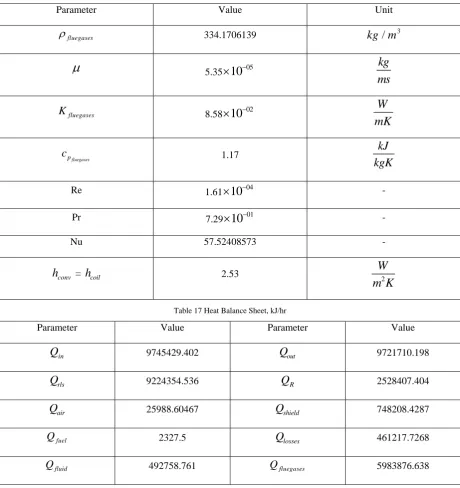
Table 16 Flue Gases Properties and Values
Parameter Value Unit
fluegases
334.1706139kg m
/
3
5.35 0510
kg
ms
fluegases
K 8.58 02
10
W
mK
fluegases
p
c
1.17kJ
kgK
Re 1.61
10
04 -Pr 7.29
10
01 -Nu 57.52408573 -
conv
h
=h
coil 2.53W
2m K
Table 17 Heat Balance Sheet, kJ/hr
Parameter Value Parameter Value
in
Q
9745429.402Q
out 9721710.198rls
Q
9224354.536Q
R 2528407.404air
Q
25988.60467Q
shield 748208.4287fuel
Q 2327.5
Q
losses 461217.7268fluid
Q 492758.761 Qfluegases 5983876.638
Above Values and the Parameters are shows that the heat balance and the other details which generates and provides proper amount of heat to the radiant heat exchanger wall and from that data CFD analysis would done on the ANSYS 14.0 Fluent (Non-Commercial Use Only) would give how much amount of heat can be carried by the fluid and the further results would obtained.
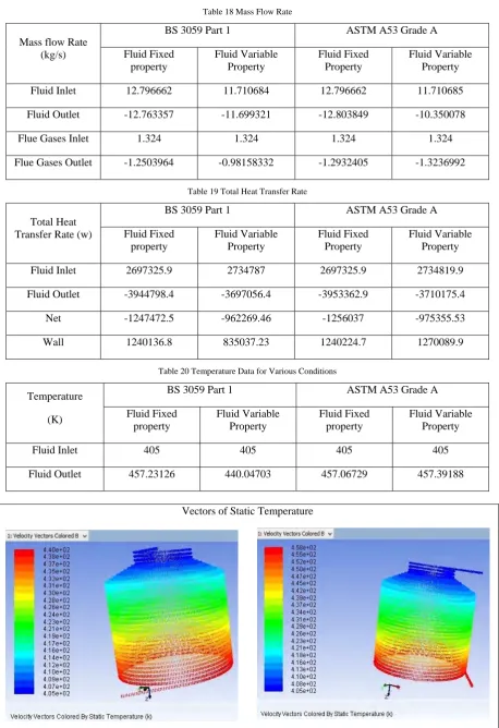
RESULTS
Table 18 Mass Flow Rate
Mass flow Rate (kg/s)
BS 3059 Part 1 ASTM A53 Grade A
Fluid Fixed property
Fluid Variable Property
Fluid Fixed Property
Fluid Variable Property
Fluid Inlet 12.796662 11.710684 12.796662 11.710685
Fluid Outlet -12.763357 -11.699321 -12.803849 -10.350078
Flue Gases Inlet 1.324 1.324 1.324 1.324
Flue Gases Outlet -1.2503964 -0.98158332 -1.2932405 -1.3236992
Table 19 Total Heat Transfer Rate
Total Heat Transfer Rate (w)
BS 3059 Part 1 ASTM A53 Grade A
Fluid Fixed property
Fluid Variable Property
Fluid Fixed Property
Fluid Variable Property
Fluid Inlet 2697325.9 2734787 2697325.9 2734819.9
Fluid Outlet -3944798.4 -3697056.4 -3953362.9 -3710175.4
Net -1247472.5 -962269.46 -1256037 -975355.53
Wall 1240136.8 835037.23 1240224.7 1270089.9
Table 20 Temperature Data for Various Conditions
Temperature
(K)
BS 3059 Part 1 ASTM A53 Grade A
Fluid Fixed property
Fluid Variable Property
Fluid Fixed property
Fluid Variable Property
Fluid Inlet 405 405 405 405
Fluid Outlet 457.23126 440.04703 457.06729 457.39188
Vectors of Static Temperature
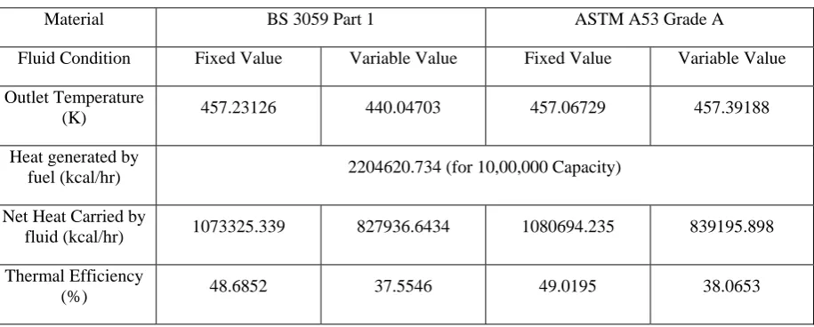
Table 21 Result Table Comparison
Material BS 3059 Part 1 ASTM A53 Grade A
Fluid Condition Fixed Value Variable Value Fixed Value Variable Value
Outlet Temperature
(K) 457.23126 440.04703 457.06729 457.39188
Heat generated by
fuel (kcal/hr) 2204620.734 (for 10,00,000 Capacity)
Net Heat Carried by
fluid (kcal/hr) 1073325.339 827936.6434 1080694.235 839195.898
Thermal Efficiency
(%) 48.6852 37.5546 49.0195 38.0653
Analytical value of the heat that can be carried during the actual process from available data at relative temperature which is given by;
Heat Carried by the fluid =
2
2
pin pout
in out
out in
c
c
V
T
T
= 749086.0312 kcal/hrCONCLUSION
From the analysis of the various results of BS 3059 and ASTM A53 in ANSYS, the following conclusions can be achieved:
1. The specific heat of ASTM A53 (461
J kgK
/
) is lower than BS 3059 (465J kgK
/
). So, the amount of heat per unit mass required to raise the temperature by one Kelvin in ASTM A53 is lower than BS 3059. Therefore, the heat transfer of the ASTM A53 is slightly higher than BS 3059.2. The number of alloying elements in ASTM A53 is higher than the BS 3059. As the alloying elements
increases, thermal conductivity decreases. Therefore, the thermal efficiency of ASTM A53 is not too much higher than the BS 3059.
3. From the available data, the cost of ASTM A53 is also lower compared to BS 3059. So, it is better option for industry.
4. The fluid outlet temperature is slightly reduced in ASTM A53 compared to BS 3059 which does not
affect the exactness of the working condition of the Thermic Fluid Heater.
5. The analysis also gives higher results compared to the actual analytical value. So, it indicates that predicted analyses can become basis for actual experiment.
REFERENCE
[1] Code of Practice for Thermal Oil Heaters (Issued under Section 18A of the Boiler and Pressure Vessels Ordinance), Boiler & Pressure Vessels Authority, Hong Kong, 1992, Chapter 2, Page no. 9-11
[2] Hasan Al-Haj Ibrahim (2010), “Fired Process Heater”, Matlab – Modelling, Programming and Simulations, Emilson Pereira Leite (Ed.), ISBN: 978-953-307-125-1, In Tech, Available From: http://www.intechopen .com/books/matlab-modelling-programming-and-simulation/fired-process-heaters
[3] Rajesh Holkar, Dr.Ompraksh. D. Hebbal (2013) , “CFD analysis of Pulverised Coal Combustion of Burner Used In Furnace with Different Radiation Models”, Department of mechanical Engineering, PDA college of Engineering, Gulbarga, IOSR Journal of mechanical and civil engineering (IOSR-JMCE), e-ISSN: 2278-684, Volume 5, Issue 2, pp 25-34.
[4] H. Verbanck (1997) , “Development of a Mathematical Model for Water-tube Boiler Heat Transfer Calculation”, Proc S AfrSugTechnol Ass -71, pp 161-171
[5] BRITISH STANDARD, BS 3059-1:1987, Steel boiler and super heater tubes - Part 1: Specification for low tensile carbon steel tubes without specified elevated temperature properties, UDC 621.184.2-034.14
[6] G. K. Sahu (1998), “Handbook of Piping Design”, New Age International (PVT) Limited, ISBN: 81-224-1141-X
[7] Technical Data Sheet of “Shell Heat Transfer Oil S2”, High Performance Heat Transfer fluid, Shell Lubricants, August 2010 Report [8] GUJTEX Catalogue, GUJTEX Engineering Company
[9] Dr.ReyedShawabkeh, “Steps for design of Furnace/ Fired Heater”, Department of Chemical Engineering, King Fahd University of Petroleum & Minerals
[10] R. K. Rajput (2007), “Engineering Thermodynamics”, Laxmi Publication (P) LTD, ISBN: 978-0-7637-8272-6, 3678
[11] ThyssenKrupp Materials International, ASTM A53, Grade A (P235TR1/2) and Grade B (P265TR1/2), Material Data Sheet applies for seamless and welded tubes of non-alloy steel with specified elevated temperature properties (October 2011)

![Table 3 Flue Gases and Fluid Boundary Conditions [3]](https://thumb-us.123doks.com/thumbv2/123dok_us/9668245.1494715/6.595.165.431.71.237/table-flue-gases-fluid-boundary-conditions.webp)
![Table 4 Proximate and Ultimate Analysis of Coal with its Properties [3]](https://thumb-us.123doks.com/thumbv2/123dok_us/9668245.1494715/7.595.66.531.118.366/table-proximate-ultimate-analysis-coal-properties.webp)
![Table 6 Data Constant for Thermal Conductivity [4]](https://thumb-us.123doks.com/thumbv2/123dok_us/9668245.1494715/8.595.68.532.77.692/table-data-constant-thermal-conductivity.webp)
![Table 9 Properties Variation of BS 3059 Part 1 [5]](https://thumb-us.123doks.com/thumbv2/123dok_us/9668245.1494715/9.595.65.530.560.768/table-properties-variation-bs.webp)
![Table 13 Geometry Data Available [8]](https://thumb-us.123doks.com/thumbv2/123dok_us/9668245.1494715/10.595.69.533.93.468/table-geometry-data-available.webp)
![Table 15Various Temperatures Required [2, 8]](https://thumb-us.123doks.com/thumbv2/123dok_us/9668245.1494715/11.595.66.533.86.238/table-various-temperatures-required.webp)