Part Performance Improvement Through Design
Optimisation Of Cooling Channels in the Injection
Moulding Process
M. A. Alhubail
1, A. I. Alateyah
1,2, D. Alenezi
1, B. Aldousiri
3[1] Advanced Polymer and Composites Research Group, School of Engineering, University of Portsmouth, UK. [2] Qassim University, Qassim, Saudi Arabia.
[3] Department of Power and Desalination Plants, Ministry of Electricity, South Surra, 13001 Kuwait, Kuwait.
Abstract--
In this study conformal cooling channel (CCC) was employed to dissipate heat of, Polypropylene (PP) parts injected into the Stereolithography (SLA) insert to form tensile and flexural test specimens. The direct metal laser sintering (DMLS) process was used to fabricate a mould with optimised CCC, while optimum parameters of injection moulding were obtained using Optimal-D. The obtained results show that optimisation of the cooling channel layout using a DMLS mould has significantly shortened cycle time without sacrificing the part’s mechanical properties. By applying conformal cooling channels, the cooling time phase was reduced by 20 seconds, and also defected parts were eliminated.
Index Term-- Optimum Parameters, Injection Moulding, Conformal Cooling Channels, Cycle Time
1. INTRODUCTION
Injection moulding is one of the most important polymer processing methods used to produce polymer parts in different shapes and sizes. The conventional method of cooling does not provide the capability of cooling injection moulded part uniformly. The cooling stage takes up quite a large portion of injection moulding cycle. Inappropriate cooling channel design leads to increase cooling time and part ejection. The injection moulding process involves the injection of a polymer melt into a mould where the melt cools and solidifies to form a plastic product [1-2]. Injection moulding is the most commercially essential of all plastic manufacturing methods, which enables the production of complex, high precision, three dimensional (3D) products at high manufacturing rates [3]. Currently, Rapid Prototyping (RP) technology is also a major player in the dies manufacturing industries. Complex mechanical fabrication has been avoided while the manufacturing cycle time to produce a mould has been shortened significantly [4].
It has been shown that the significant parameters that affect product quality in injection moulding processes are injection pressure, melt temperature, injection speed, coolant temperature, packing time, packing pressure, cooling time, etc. [5]. However, in a study [6], it was suggested that using design of experiment (DOE) methods to optimize the parameters in the injection moulding process could serve as an effective technique in finding the best process parameters, which could successfully eliminate the undesirable defects, and significantly improve the quality of the parts produced. Though, the optimal injection moulding processes design is
strongly required utilisation of the DOE methods has been recommended in a number of studies [7, 8, 9, 10, and 11].
The primary advantages of the DOE include the simplification of the experimental plan and visibility of the interaction among the different parameters. Thus, reducing the number of experimentation runs can lead to a significant saving of time and cost. Many studies have used the full factorial design to optimize the injection moulding parameters [12, 13, 14, and 15]. Most recently, the DMLS has been strongly accepted in Rapid Tooling (RT) sectors since the appropriate metal powder could be provided to produce metal components and tools in the functional materials. However, the production quality depends on its composition and solidification. Hence, the accuracy, wear resistance and mechanical properties are critical factors of choices in the rapid tooling mould in DMLS [16]. DMLS has led to a major time reduction in tool-making due to the possibility and successful sintering of metal powders it offers [17].
experimentation plan, and Polypropylene was used for the injection moulding process. Processed parts then were tested in order to evaluate mechanical properties and warpage.
2. METHODOLOGY
The main objective of this experimental study is to reduce the cycle time during injection and ejection processes; hence the default cycle time in the injection moulding is 60 seconds. Figure 1 shows the cycle time of our laboratory injection moulding machine, indicating that cooling time consumes most of the injection moulding cycle time. Therefore, the proper solution of minimizing cooling time, such as cooling channels, possibly will reduce the cycle time of the injection moulding process.
Fig. 1. Percentages and timing of injection moulding process
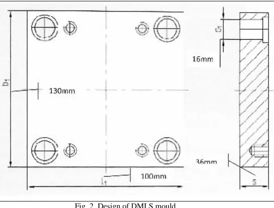
However, reducing the cycle time should be done without sacrificing the mechanical strength of the Polypropylene produced parts, namely, tensile strength and flexural strength. Accordingly, an initial experiment was done in a conventional method at default settings, cycle time = 60 sec, in order to compare the outcome results. Primarily, an experimentation mould was manufactured using direct metal laser sintering (DMLS), using powdered Maraging steel. The DMLS allows high flexibility to build conformal cooling channels, and also the steel mould can provide high strength and appropriate thermal properties for the injection process. Moreover, a Stereolithography (SLA) rapid prototyping system was used to produce the tooling parts. The SLA insert was built layer-by-layer using SL5510 material. The SLA tool part has been used as an insert into the DMLS mould cavity to produce Polypropylene tensile and flexural test specimens (see Figure 2). Testing was done according to the ISO 527-2. The DMLS mould was designed using a Finite Element Analysis (FEA) system; that was done according to several thermal analyses and manufacturing simulations in order to determine the optimum layout of the cooling channels, which should dissipate the heat from the SL5510 insert to the mould as uniformly as possible. The main aim of employing conformal cooling channels in the DMLS mould is to minimize the
thermal and physical stresses that influence the SLA tool during the injection process.
Fig. 2. Design of DMLS mould
The aim of the simulation was to determine the optimum layout of the cooling channels when producing the Polypropylene tensile specimen at 210oC. Figure 3 illustrates the rising thermal stress on the injected part. Therefore, certain assumptions for the simulation set-up were pointed out, as follows:
Supplied geometry represents 50% of symmetrical parts.
Perfect thermal contact at polypropylene-tool and tool-insert interface.
Target cooling temperature = heat deflection temperature (approx 60oC).
Cooling is not applied during injection.
Thermal energy is transferred from moulding by pure conduction.
Fig. 3. Thermal stresses affecting moulding area before applying cooling channels
heat could be conducted through the various components to meet the condition.
This manufacturer data could then be used to specify the cooling system requirements. Through assuming an elevated moulded part temperature of 210oC, and allowing the Maraging steel tool block to serve as the low temperature (20oC) sink, yielded the following results:
• The SL5510 insert serves to act as a storage insulator. • Heat is dissipated much slower in the part than in the
injection runner.
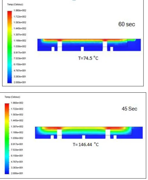
The injection moulding process real-time was simulated; accordingly the SLA insert was observed to understand the variation between heat transfer at cooling time standard = 60 sec and reduced time of 45 sec. It can be seen in Figure 4 that heat was drastically raised on the SLA insert at 45 sec. In order to determine the layout of the conformal cooling channels, it was imperative to specify the most critical areas during the injection moulding, which needs higher heat dissipation according to the accumulated heat stress.
As a demonstration of the limitations imposed on cycle time by the use of the SL5510 resin insert, Figure 5 indicates the presence of the block cooling measures, during continuous exposure to 210oC, the material of the insert component heavily influences the heat dissipation from the test piece.
Fig. 4. Heat rising in both inserts in cycle time of 60sec and 45sec.
The volume flow rate of 8 litres/min facilitates a cooling capacity of 5kW (based on realistic fluid properties and a wall-fluid temperature difference), much in excess of the
requirements of the tool. The proposed geometry is based on the design criteria as detailed in Figure 5. Additionally, based on a Moldflow simulation, it can be concluded that:
Simulation Assumptions:
• Turbulent flow within cooling channels. • Inlet coolant temperature 0oC.
• Initial component temperatures of 20oC.
• Continuous exposure to 210oC test piece (high duty-cycle).
Design Assumptions:
• Adequate cooling to maintain block below PP heat deflection temperature.
• Provides preferential cooling to region of mould tool. • Induces turbulent flow throughout channels to maximise thermal transport at 8l/min volume flow rate.
Fig. 5. Recommended cooling system
than the system requires. The Maraging steel tool block acts as a vast thermal sink, requiring 1579J of energy to increase by 1oC. Cooling channels within the block would only serve to maintain uniformly heat transfer under heavy-duty cycles. However, there was a real need for actual experimentation to provide evidence of the profitability of applying such cooling channels in the proposed DMLS mould, which was fabricated using Maraging Steel MS1, to compare the outcome with the simulation result.
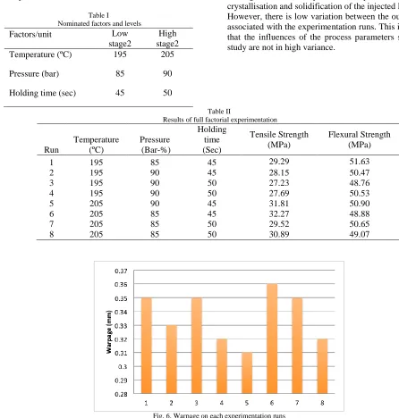
The selection of design of experiment (DOE) full factorial design in this study was vital due to its high capability of decreasing the number of runs during the experiment. Table 1 shows the variable factors with their associated setting levels in this experiment.
Table I
Nominated factors and levels
3. RESULTS AND ANALYSIS
After running the experiment, the specimens for each experimental run were collected, and tested according to the ISO 572-1: 1996. Each run included five tested specimens; the average of these test values was recorded as response outcome. Table II illustrates the average values of the tensile and flexural test for each run. Looking at the tensile and flexural strength testing result values in Table 2, it can be seen that although cooling time has been reduced by about 45% by using conformal cooling channels, the Polypropylene produced parts did not lose their flexural or tensile strength or were highly influenced by warpage. Figure 6 shows the warpage average of each run. It can be concluded that the cooling channels have provided adequate cooling during the crystallisation and solidification of the injected Polypropylene. However, there is low variation between the outcomes results associated with the experimentation runs. This is an indication that the influences of the process parameters settings in this study are not in high variance.
Table II
Results of full factorial experimentation
Run
Temperature (ºC)
Pressure (Bar-%)
Holding time (Sec)
Tensile Strength (MPa)
Flexural Strength (MPa)
1 195 85 45 29.29 51.63
2 195 90 45 28.15 50.47
3 195 90 50 27.23 48.76
4 195 90 50 27.69 50.53
5 205 90 45 31.81 50.90
6 205 85 45 32.27 48.88
7 205 85 50 29.52 50.65
8 205 85 50 30.89 49.07
Fig. 6. Warpage on each experimentation runs
Using the D-optimal prediction system for the results of full factorial design, as shown in Figure 7, can provide prediction
of parameters’ settings performance in real practice. According to the collected data of experimentation runs, the
Factors/unit Low
stage2
High stage2
Temperature (ºC) 195 205
Pressure (bar) 85 90
response optimisation system allows the prediction of the optimum combination of variable parameters (temperature, pressure, and hold) considering the targeted response (tensile and flexural strength). Consequently, Figure 7 shows that D-optimal analysis indicates that the optimum combination of process parameters for targeted tensile strength = 31.7 MPa, as follows: temperature = 205°C (high level), pressure = 90%
(high level), and holding = 45 sec (low level). Similarly, Figure 8 shows D-optimal for targeted flexural strength = 51.6 MPa, the optimum combination as follows: temperature = 205°C (high level), pressure = 90% (high level), and holding = 50 sec.
Fig. 7. Response prediction plot for optimum parameters’ settings (tensile strength)
Fig. 8. Response prediction plot for optimum parameters’ settings (flexural strength)
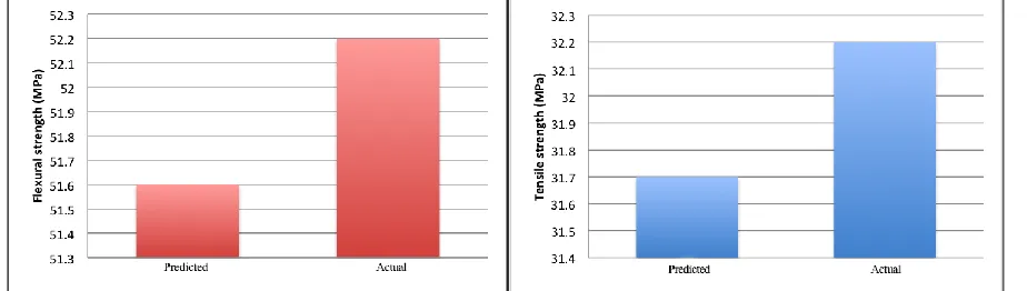
At the end of the experimentation, a confirmation experiment of predicted results is performed to verify the performance of the predicted optimum settings, and also whether the cooling channels’ application has reduced cooling time during the actual practice. Figure 9 shows the results of the confirmation
experiment that compared between the predicted results from the optimal design analysis and the actual results. It shows very small differences between actual results and predicted results, which confirm the predicted results earlier.
Fig. 9. Predicted versus actual results
In addition, Figure 10 illustrates the phases of the injection moulding process; it shows cycle time in seconds and the elevated pressure during the process. By applying conformal cooling channels, the cooling time phase was reduced by 20 seconds as indicated in Figure 10, and also defected parts were eliminated. It led to conclude that thermal and residual stresses
Fig. 10. Cycle time of injection moulding process 4. CONCLUSION
In The Conformal cooling channels (CCC) is an important technique to get enhanced part quality and shorter cycle time in the injection moulding process. This study showed that CCC manufactured by DMLS process shows as a viable technique to improve quality and reduce the cycle time. The optimisation of thermal stress using a Finite Element Analysis system was key to enabling the reduced cycle time of the injection moulding process. It allowed determining the layout of the conformal cooling channels, checking conformity of the fluid flow, and also provided prediction of the mould and mould insert integrity during the process. It can be concluded that developing the CCC in DMLS has significantly reduced the cooling time up to 40% without compromising the tensile and flexural properties of Polypropylene moulded parts.
REFERENCES
[1]. Seow, L., & Lam Y. (1997). Optimizing flow in plastic injection moulding. Journal of Materials Processing Technology. 72 (3), pp. 333-341.
[2]. Drummer, D & Messingschlager, S. (2014). Material
Characterization of Strontium Ferrite Powders for Producing Sintered Magnets by Ceramic Injection Molding
(MagnetPIM). ,
Article ID 651062, 2014. doi:10.1155/2014/651062.
[3]. Goodship, V., & Love, C. (2002) Multi-Material Injection Moulding. Smithers Rapra, Shrewsbury, GBR. United Kingdom. ISBN 9781859573273 9781859574218.
[4]. Zhang, L., & Liu, H. (2009). Application of Rapid Prototyping Technology in Die Making of Diesel Engine. Tsinghua Science and Technology 14(1), pp. 127-131.
[5]. Chin, F. (2003). Manufacturing Process Optimization for Wear Property of Fibre Reinforced Polybutylene Terephthalate Composites with Grey Relational Analysis. Wear. 254 (3-4), pp. 298-306.
[6]. Huang, M., & Tai, C. (2001). The effective factors in The Warpage Problem of an injection-molded part with a thin shell feature. Journal of Materials Processing Technology. 110 (1), pp. 1–9.
[7]. Park, K., & Ahn, J. (2004). Design of Experiment Considering two-way interactions and its application to injection moulding processes with numerical analysis. Journal of Materials Processing Technology. 146 (2), pp. 221-227.
[8]. Loh, N., & German, R. (1996). Statistical analysis of shrinkage variation for powder injection moulding. 59 (3), pp. 278-284. [9]. Lu, X., & Khim, L. (2001). A statistical experimental study of the
injection moulding of optical lenses. Journal of Materials Processing Technology. 113 (1-3), pp. 189-195.
[10]. Yang, Y., Shie, J., Yang, R., & Chang, H. (2006). Optimization of Injection Moulding Process for Contour Distortions of Polypropylene Composite Components via Design of Experiments Method. Journal of Reinforced Plastics and Composites. 25 (15), pp. 1585-1599.
[11]. Villmow, T., Pegel, S., Potschke, P., & Wagenknecht, U. (2008). Influence of injection moulding parameters on the electrical resistivity of polycarbonate filled with multi-walled carbon nanotubes. Composites Science and Technology. 68 (3-4), pp. 777-789.
[12]. Kurtaran, H., Ozcelik, B., & Erzurumlu, T. (2005). Warpage optimization of a bus ceiling lamp base using neural network model and genetic algorithm. Journal of Materials Processing Technology. 169 (2), pp. 314–319.
[13]. Sha, B., Dimov, S., Griffiths, C., & Packianather, M. (2007). Investigation of micro-injection moulding: Factors affecting the replication quality. Journal of Materials Processing Technology. 183 (2-3), pp. 284-296.
[14]. Oktem, H., Erzurumlu, T., & Uzman, I. (2007). Application of Taguchi optimization technique in determining plastic injection molding process parameters for a thin-shell part. Materials & Design. 28, pp. 1271–1278.
[15]. Lin, T., & Chananda, B. 2004. Quality Improvement of an Injection-Moulded Product Using Design of Experiments: A Case Study. Quality Engineering. 16 (1), pp. 99-104.
[16]. Khaing, W., Fuh, H., & Lu, L. (2001). Direct metal laser sintering for rapid tooling: processing and characterization of EOS parts. Journal of Materials Processing Technology. 113, pp. 269-72. [17]. Simchi, A., Petzoldt, F., & Pohl, H. (2003). On the development of
direct metal laser sintering for rapid tooling. Journal of materials processing technology. 141 (3), pp. 319.
[18]. Xu, X., Sachs, E., & Allen, S. (2004). The design of conformal cooling channels in injection moulding tooling. Polymer Engineering & Science. 41 (7), pp. 1265-1279.
[19]. Sanchez, R., Aisa, J., Martinez, A., & Mercado, D. (2012). On the relationship between cooling setup and warpage in injection molding, Measurement 45 (5) (June) pp. 1051-1056.
[20]. Hassan, H., Regnier, N., Pujos, C., Arquis, E., & Defaye, G. (2010). Modeling the effect of cooling system on the shrinkage and temperature of the polymer by injection molding, Applied Thermal Engineering 30 (13) (Sept.) pp. 1547-1557.
[22]. Pichon, J.F. (2001). Injection of Plastic Materials, Dunod, Paris, France.
[23]. Agazzi, A., Sobotka, V., LeGoff, R., & Jarny, Y. (2013). Optimal cooling design in injection moulding process: A new approach based on morphological surfaces. Applied Thermal Engineering 52, pp. 170-178.
[24]. Dimla, D., Camilotto, M., & Miani, F. (2005). Design and optimisation of conformal cooling channels in injection moulding tools. Journal of Materials Processing Technology. 164 (165), pp. 1294-1300.
[25]. Dalgarno, K., & Stewart, T. (2001). Manufacture of production injection mould tooling incorporating conformal cooling channels via indirect selective laser sintering. Institution of Mechanical Engineers. Part (B). 215 (10), pp. 1323.
[26]. Masood, S., & Jeyasingh, V. (2007). Process time reduction in blow moulding process with conformal cooling. Society of Plastic Engineers. (2), pp. 914-918.
[27]. Saifullah, A., Masood, S., & Sabarski, I. (2009). New Cooling Channels Design for Injection Moulding. World Congress on Engineering (WCE). Vol I.
[28]. Tahboub, K., & Rawabdeh, I. (2004). A design of experiments approach for optimizing an extrusion blow moulding process. Journal of quality in maintenance engineering. 10 (1), pp. 47-54. [29]. Derringer, G., & Suich, R. (1980), "Simultaneous optimization of
![Fig. 10. Cycle time of injection moulding process [8]. Loh, N., & German, R. (1996). Statistical analysis of shrinkage](https://thumb-us.123doks.com/thumbv2/123dok_us/1356715.1644565/6.612.177.437.56.261/cycle-injection-moulding-process-german-statistical-analysis-shrinkage.webp)