DESIGN AND DEVELOPMENT OF DC-DC BOOST CONVERTER
FOR TRACTION SYSTEM
Nilambari V. Devarkar1, Ashpana Shiralkar2
1. INTRODUCTION
Regenerative braking is energy mechanism which slows down a vehicle by converting its kinetic energy into electrical energy that can either be used immediately or stored for future use. In Indian Railways at present, WAP-5, WAP-7 and WAG-9 class of 3phase locomotives are capable of saving up to 20% and 3phase electrical multiple units (EMU) are capable of saving up to 30% energy through regenerative braking. Currently, the regenerated energy is fed back into the OHE and is utilized only if the OHE is receptive i.e. if there is a train load present in the section. This immediate energy exchange between trains needs cooperative operation between the braking and the accelerating trains. But in the present scenario of Indian Railways, there are mixed train operations, where the same line is utilized by Semi-High speed, Passenger and Goods trains. Hence, the traction and braking trains are very difficult to be matched in the time, space and driving strategy. Further, any energy produced above 30% through regenerative braking by 3 phase locomotives is not usable currently in Indian Railways, and is dissipated rheostatically in the form of heat [1]. An effort has been made through this paper to study the DC-DC boost converter which converts the regenerated power from the breaking of train and to charge the batteries. DC-DC boost converter discharges the stored energy to feed the powering train.
In the railway now carrying out activities to reduce CO2 emission to improve the environment on the earth. The energy saving by the regeneration from the breaking train is one of such activities. The conventional method to recover the regenerated power has been to use the thyristor inverters located at the railway substations. The thyristor inverters return the DC power to the AC network. Then, they need AC power lines to be connected [2] the new method is now proposed to use Battery Energy Storage Systems (BESSs) which are now found in micro-grids or in renewable power generations.[3] One of the advantages of BESS in railway feeder systems is location free. Namely, the BESS can be installed any places where the AC power line connection is not provided in contrast to the thyristor inverters. It is suitable for power management of the railway.
This paper describes the development of such a DC-DC Boost converter. The paper is organized as follows. In Section II, Literature Survey of DC-DC Boost Converter, section III configuration is introduced, and specifications of the main circuit of the developed DC-DC Boost converter are presented. In Section IV, Design Calculations DC/DC Boost converter is presented. Section V, Main circuit tests report. Section VI concludes the paper.
2. LITERATURE SURVEY
Eric J. Carlson [6] Presented low power boost converter for thermoelectric energy harvesting. This converter supplies 1 V output from input voltages ranging from 20mV to 250 mV. Output power obtained is 25mW and effciency-75A. Richelli [7] presented a dc-dc boost converter that produced 1.2V from an input of 100 mV, with output current of 220uA and efficiency of 30 Dongwon Kwon [8] presented a single-inductor piezoelectric harvester by investing energy from the battery into the transducer. The idea is to strengthen the electrostatic force against which vibrations work. This way, the circuit draws more power from the transducer, up to 79 W from a 2.7 cm piezoelectric cantilever that is driven up to 0.25 m/s2. Of the 79 W drawn at 0.25 m/s2 when investing 91 nJ of battery energy, the system outputs 52 W, which is 3.6 times more output power than the 14.5W that a full-wave bridge rectifier with zero-volt diodes at its maximum power point can deliver from the same source. Power-conversion efficiency peaks at 69. Sijun Du [9] presented an inductor less circuit, which configured two piezoelectric materials in parallel or series by periodically evaluating their ambient excitation level. A 4.5 times boost in harvested energy was obtained compared to full bridge rectifier without inductor. The design consists of two PTs (bimorph
1 Electrical Department, AISSMS's Institute of Information Technology, Pune, India 2 Head of Department, AISSMS's Institute of Information Technology, Pune, India
International Journal of Latest Trends in Engineering and Technology
Vol.(14)Issue(1), pp.053-057
DOI: http://dx.doi.org/10.21172/1.141.10
e-ISSN:2278-621X
Abstract- DC-DC Boost converters are used to increase the low D.C. voltage to high D.C. voltage. This increased D.C. voltage can be used for powering the battery energy storage system. Converting regenerated power from a braking train and charges the batteries. This paper presents the modified boost converter which we can be used in Indian traction system. The proposed boost converter produces a constant 14.2 V D.C. Duty cycle of the PWM signal is so adjusted so as the output voltage is monitored accordingly.
mode voltage at P12 and Vs compared and if condition satisfied then EXCI is sent to power management and calibration mode ends. DC-DC boost converter generates high voltage driving gates in connection switching.Liao Wu [10] presented a piezoelectric energy harvesting circuit, which integrates a Synchronized Switch Harvesting on Inductor (SSHI) circuit and an active rectifier.
The SSHI circuit in this paper inserts an active diode on each resonant loop, which ensures flipping of the capacitor voltage at optimal times and eliminates the need to tune the switching time. The diodes of the SSHI circuit are also used as a rectifier to further simplify the controller. The key advantage of the circuit is a simple controller, which leads to low power dissipation of the proposed circuit to result in high efficiency. The circuit in this paper is self-powered and capable of starting even when the battery is completely drained. Measured results indicate that the circuit increases the amount of power harvested from a piezoelectric cantilever by 2.1 times when compared with a full bridge (FB) rectifier and achieves a power conversion efficiency of 85. Dejan Rozgic
Presented a thin film, array based TEH (thermoelectric energy Harvester) with a surface area of 0.83cm2.THE autonomously supplies a power management IC. The IC utilizes a single-inductor topology with integrated analog maximum power point tracking (MPPT); resulting in a 68power density compared to the state-of the-art. The system showed autonomous operation down to 65-mV TEH input.
After the great east Japan earthquake in March 2011, BESSs are also required to be an emergency power supply in the event of AC power outage [3]. In this work, the BESS is developed to feed the power for trains to move to the nearest stations when the rectifier station is not available in the event of AC power outage due to earthquake or some sort of natural disaster. For connecting the DC feeder and the batteries, a high voltage and high-power bilateral DC-DC converter is required to be developed. The DC-DC converter converts the regenerated power from the breaking train and to charge the batteries, and discharges the stored energy to feed the powering train. This paper describes the development of such a DC-DC boost converter. In this paper central idea is to make such DC-DC boost converter which is used to boost the output voltage and charge the battery.
3. SYSTEM CONFIGURATION
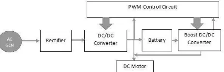
Figure 1 block diagram of prototype model traction system
Figure 1 is the block diagram of prototype model of dc-dc boost converter design for traction system. In this dc –dc boost converter is used which boosted the output voltage up to 14.2 V. lead acid battery is used. To control the output of boost converter PMW Tl494 is used.
Normally battery of railways charged through 25KV catenary overhead supply. Rectifier house is near to each station. Regenerative energy generated from braking action is normally fed back to OHE, here use this regenerative power from braking action to stored charge in the battery.
3.1 Specification
A. DC –DC Boost Converter output voltage 14.2V. Lead acid battery 12V. 12V series motor. ARDUINO UNO ATMEGA328P-PU controller is used. Obstacle sensor is also used to sense the obstacles.
3.2. Interconnected operation mode
Figure 2 Interconnected operation mode
3.3. Isolated mode
If overhead supply isolate due to any sort of reason like earthquake or rectifier station is not near then train stop on the track. It will not moving towards nearest station. If train stop at remote place then it’s difficult to on board passengers too. This situation occurs in the Japan so they made BESS. Using BESS train will moves towards the nearest station. In this paper try to implement a prototype model of train. In future will experiment on Indian railways by using maximum capacity DC-DC boost Converters. In India still mostly lead acid batteries are used. Some places lithium ion batteries also started using in Indian railways. Energy generated from regenerative braking will sent to OHE.
In this prototype model try to store the charge in the battery and use this energy whenever natural disaster happened. Proposed prototype model as shown in figure 1.
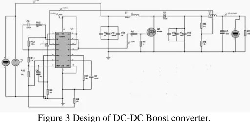
For proposed model a boost DC – DC converter which will boost output voltage so as charge battery. Design of boost DC-DC converter as shown in figure 3
Figure 3 Design of DC-DC Boost converter.
Figure 3 shows the design of DC-DC Boost converter. Output voltage of DC-DC Boost converter is 14.2 V. Output voltages remains same for any variation in input voltage. This output voltage control using PMWTL494.
4. DESIGN CALCULATIONS
The following four parameters are needed to calculate the power stage: Input Voltage Range: VIN (min) and VIN(max)
= 12V & 20V V nominal = 13.5V 2. Nominal Output Voltage: VOUT = 14.2 V
3. Maximum Output Current: IOUT (max) = 2 Amp
Integrated Circuit used to build the boost converter. This is necessary, because some parameters for the calculations have to be taken out of the data sheet.
Calculate the Maximum Switch Current
D=1 – (1)
VIN (min) = minimum input voltage = 12V VOUT = desired output voltage = 14.2 V
= efficiency of the converter, e.g. estimated 80% D = 0.65 = 65%
Inductor Selection
L= (2)
IOUT(max) = maximum output current necessary in the application
Rectifier Diode Selection
To reduce losses, Schottky diodes for fast switching diode should be used. The forward current rating needed is equal to the maximum output current
If = Iout (max) (3)
IF = 2 Amp
IF = average forward current of the rectifier diode
Iout (max) = maximum output current necessary in the application Select 5408 diode
Input Capacitor Selection
Use MLCC type 0.1 uf capacitor to maintain ESR Output Capacitor Selection
= 2 *0.65 / (20000 * 6.31) = 10uf (4)
but use 100 uf,50V
ΔIL = inductor ripple calculated
= 1 * [(2/ (1-0.65)) + (1.2/2)] = 6.31 (5)
Selection of MOSFET
Maximum current drawing capacity = 2Amp
Output voltage = 14.2V
Power dissipation= 2 * 14.2 = 28.4w (6)
5. MAIN CIRCUIT TESTS
Figure 4 Input vs. Output voltage correspond to distance of Dc-Dc Boost Converter
6. CONCLUSION
This paper presents implementation of a prototype model for traction system. Indian railway regenerative energy sent to over head equipment remaining get wasted in form of heat, so this paper try to build up a DC-Dc Boost converter which charge the battery and use this energy store in battery when train stop due to natural disaster, energy from battery is used to move the train to nearest station. As perceived from above 12V battery charge from DC-DC Boost converter. Output voltage of converter remains same that is 14.2V. For the Indian railways we can use this technology which not only used regenerative energy but also CO2 emissions get reduced.
7. REFERENCES
[1] Varsha Singh‖ Efficient Utilization of Regenerative Braking in Railway Operations‖ IRJET, Vol. 04 Issue: 12, pp. 1421, 2017.
[2] [2] Y. Oura, Y. Mochinaga, H. Nagasawa, "Railway Today 3 – Railway Power Feeding System," Japan Railway and Transportation Review, vol. 16, pp.48,58, 1998.
[3] Z.Li, S.Hoshina, N.Satake, and M.Nogi,‖ Development Of DC/DC Converter for Battery Energy Storage Supporting Railway DC Feeder Systems‖ IEEE Transactions on Industry Applications, pp. 1-2, 2016.
[4] N. Kawakami‖Development and held experiences of stabilization system using 34MW NAS batteries for a 51MW windfarm" ,IEEE, pp.4-7, 2010. [5] Y. Kono ―JR East Japan Railway Company Series HBE210 Traction Power Supply System", pp 510, 2015.
[6] Eric J. Carlson, Kai Strunz, and Brian P.Otis,’’ A 20 mV Input Boost Converter with Efficient Digital Control for Thermoelectric Energy Harvesting‖ IEEE Journal of Solid-State Circuits, Vol. 45, No. 4, pp 741-749, 2010.
[7] Anna Richelli, Luigi Colalongo, Silvia Tonoli, and Zsolt M. Kovacs-Vajna,‖ A 0.2−1.2 V DC-DC Boost Converter for Power Harvesting Applications, IEEE Transactions On Power Electronics, VOL. 24, NO. 6, pp1541-1545, 2009
[8] Dongwon Kwon, Gabriel Alfonso Rincon-Mora,‖ Single-Inductor 0.35μm CMOS Energy-Investing Piezoelectric Harvester‖, IEEE International Solid-State Circuits Conference, pp78-79, 2013.
[9] Sijun Du, Yu Jia, Ashwin A.‖ An Efficient Inductor-less Dynamically Configured Interface Circuit for Piezoelectric Vibration Energy Harvesting‖, IEEE Transactions on Power Electronics,pp—1-17,2016.
[10] Liao Wu, Xuan-Dien Do, Sang-Gug Lee, and Dong Sam Ha,‖ A Self-Powered and Optimal SSHI Circuit Integrated with an Active Rectifier for Piezoelectric Energy Harvesting.‖, IEEE Transactions On Circuits And Systems–I: pp1-10, 2016.
[11] Dejan Rozgi, Dejan Markovi,‖ A Miniaturized 0.78-mW/cm2 Autonomous Thermoelectric Energy-Harvesting Platform for Biomedical Sensors‖,IEEE Transactions On Biomedical Circuits And Systems ,pp 1-10,2017.
[12] V. V. Subrahmanya Kumar, Bhajana, Pavel, Drabek, Pramod Kumar Aylapogu, ―A Novel ZVS Non-isolated Bidirectional DC-DC Converter for Energy Storage Systems", IEEE, 978-1, pp.663, 2017
[13] T. Kobayashi, "Power electronics technology in smart grid projects -Applications and experiences-," Power Electronics Conference (IPEC-Hiroshima 2014 - ECCEASIA), 2014 International, pp.1868, 1873, 18-21 2014.
[14] Jain, Manu, Matteo Daniele, and Praveen K. Jain. \A bidirectional dc-dc converter Topology for low power application", IEEE, pp. 4: 595-606,2000. [15] Hamid R. Karshenas, Hamid Daneshpajooh, Alireza Safaee, Praveen Jain and Alireza Bakhshai, Bidirectional DC-DC Converters for Energy
Storage Systems".