Effect of Complex Geometry of Wavy Fin on the
Performance of Wavy fin Equipped Solar Air Heater
Abhishek Priyam
*, Prabha Chand
Mechanical Engineering Department, N.I.T Jamshedpur-831014, India. *Corresponding Author. Tel: +91-8797181859
Abstract-- In this paper, an attempt has been made to analyze the effect of system parameters on the thermal and thermohydraulic efficiency of a wavy finned solar air heater. The performance of the wavy finned solar air heater depends on the complex geometry of wavy fin, such as fin spacing ratio(FP/2A), flow length ratio(Ld/L) and flow cross section aspect ratio(FP/Fh). An analytical investigation on the various complex geometries showed that the maximum thermal efficiency of 80.18%, 79.59% and 79.6% and the maximum thermohydraulic efficiency of
72.6%, 76.4% and 73.2% has been found for the FP/2A=1, FP/Fh=0.4 and Ld/L=10 respectively. Furthermore, wavy fin solar air heater resulted higher thermal efficiency of the order of 2.8 times and thermohydraulic efficiency of the order of 2.6 times as compared to plane solar air heater. Overall, both thermal efficiency and thermohydraulic efficiency of wavy finned solar air heater is superior.
Index Term-- fin spacing ratio; flow length ratio; aspect ratio; thermal efficiency; wavy fin; solar air heater.
Nomenclature
Ac Collector area (m2) Dimensionless Numbers
A Amplitude of wavy fin (mm) Pr Prandtl number
Afr Minimum free flow area (m2) Re Reynolds number
Ap Area of absorber plate (m
2
) Nu Nusselt number
Ar Total heat transfer area (m2) j Colburn j -factor
Fh Height of fin (mm) f Friction factor
Fp Wavy fin spacing (mm)
G Mass velocity (kg/s-m2) Greek Letters
H Spacing between absorber plate and bottom
plate (m)
P
Pressure drop (N/m2)
he Effective heat transfer coefficient (W/m2-K) Density of air (kg/m3)
hfb Convective heat transfer coefficient
between air and bottom plate(W/m2-K)
Collector tilt angle ()
hff Convective heat transfer coefficient
between air to air(W/m2-K)
Stefan-Boltzmann Constant
(5.67*10-8 W/m2K4)
hfp Convective heat transfer coefficient
between air and absorber plate(W/m2-K)
ef f
Effective efficiency
ka Thermal conductivity of air (W/mK) C Emissivity of glass cover (0.88)
kGI Thermal conductivity of G.I sheet (W/mK) f Fan efficiency (0.65)
kins Thermal conductivity of insulating material
(W/mK)
ins Thickness of insulation (m)
L' Actual length of wavy fin (m) m Motor efficiency (0.88)
Ld Length of the collector/ Absorber plate (m) P Absorber plate emissivity(0.95)
Ngc Number of glass covers Th Thermal efficiency of power plant (0.35)
P Porosity th Thermal efficiency of solar air heater
Pm Mechanical Power (W) tr Transmission efficiency (0.92)
Qu Useful thermal energy gain (W/m2) Area enhancement factor
L Wavelength of wavy fin (mm) ()e Effective transmittance absorptance
product
Tfo Outlet air temperature (C) f Fin efficiency
Tpcal Calculated Mean plate temperature (K) f Thickness of fin (m)
1. INTRODUCTION
Flat plate solar air heaters transform solar radiant energy into heat energy of flowing air through the channel duct. These are commonly used for space heating and crop drying applications. Due to their simple construction, cost effectiveness and easy maintenance it is more accepted as compared to solar water heater. It also eradicated the freezing and leakage problem which may encountered by solar water heating systems. The low thermal efficiency and the low heat storage capacity leads to major drawback of solar air heating systems. Various methods have been examined with various designs for the enhancement of the performance of solar air heater[1]. Extended or finned surfaces, packed beds, roughness geometries are widely used in solar air heater to enhance the heat transfer and reduce the size.
The effect of flow passage dimensions on the efficiency, the air temperature enhancement and the pressure drop were tested on five various configurations of corrugated and plane solar air heaters[2]. Thermal performances of seven solar air heaters of conventional design were studied by using one or two pass air collector and one or two glass cover[3]. Another study was carried out to determine the comparative performance of one pass, corrugated, solar air heaters having different widths of air channel and for different specific mass flow rates of air[4]. Experimental investigation have been carried out to evaluate the performance of a "V" corrugated plate solar air heater during a clear day in summer and winter[5]. Several experimental investigations, having distinct types of roughness materials, have been carried out to improve the heat transfer from the absorber plate to air flowing in solar air heaters[6]. Aluminium cans were used on absorber plate to forecast the thermal performance of a double duct solar air heater[7]. Thermohydraulic Performance of a solar air heater having 60 v-down discrete rib roughness on the absorber plate has been studied experimentally[8]. Double pass finned plate and v-corrugated plate solar air heaters were investigated theoretically and experimentally[9].
An effective way to enhance heat transfer is the addition of fins in the direction of fluid flow. Various fin geometries, such as plane, wavy, offset strip, perforated and multi-louvered fins, they, apart from increasing the surface area density of solar air heater, also improve the convection heat transfer
coefficients. Among these, wavy fins are considered as most promising for their simplicity of manufacture and potential for better thermo hydraulic performance. The various performances of plane fins and other geometries have been studied by many researchers [10-14]. Offset rectangular plate fin absorber plate have been studied numerically and experimentally [15-16]. Offset rectangular plate fin absorber plate have been studied for the optimized thermal performance with various glazing [17]. However, the study of wavy finned solar air heater is very limited. In many studies, wavy fins were tested experimentally or theoretically in heat exchangers[18-20]. A recent paper by Priyam & Chand [21] on the wavy finned solar air heater shows the effect of fin spacing and mass flow rate on the performances of wavy fin solar air heater. But the performance of wavy fin solar air heater depends on the complex geometry of wavy fin, such as corrugation aspect ratio (2A/L), fin spacing ratio (FP/2A), flow
length ratio (Ld/L) and flow cross-section aspect ratio (FP/Fh).
We chose to study the effect of complex geometrical parameters of wavy fin on the various performances of wavy finned absorber solar air heater.
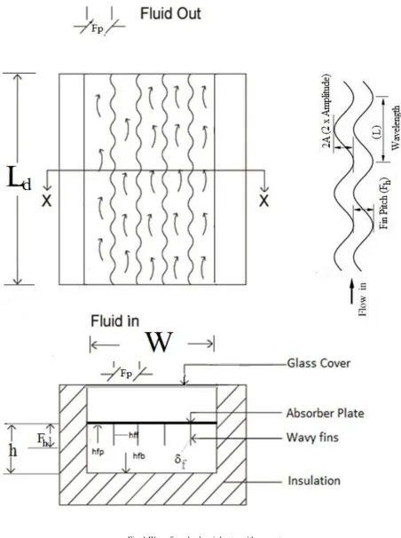
In this paper, a theoretical study of a solar flat plate collector is presented and provided with wavy fins arranged in to the air channel duct. These wavy fins are of triangular profile with round corners, oriented parallel to the fluid flow and disturbances occur between successive amplitudes. This disturbance permits to associate the fluid velocity and temperature, and this association depends on the length of interruption. The development of boundary layers denotes a higher heat transfer coefficient than in fully developed flow. The schematic diagram of a wavy finned solar air heater and the geometrical parameters are shown in fig.1. The heat transfer coefficients and pressure drop for the solar air heaters with different geometrical configurations are reported in terms of thermal efficiency and effective efficiency as a function of mass flow rates and temperature rise parameters.
2. THEORETICAL ANALYSIS
The wavy finned solar air heater is shown in fig.1. The governing equations are obtained from energy balance equations of the various components of the wavy finned solar air heater. These equations are obtained:-
For the absorber plate
(
)
. .
(
)
.2. . . .
(
)
. .
(
)
t pm a fp pm f ff f f pm f r pm bm
S
U T
T
h w dx T
T
h
h dx
T
T
h w dx T
T
(1)For the bottom plate,
. .
(
)
. .
(
)
. .
(
)
r pm bm fb bm f b bm a
h w dx T
T
h w dx T
T
U w dx T
T
(2)For the air stream,
.
p.
f fb. .
(
bm f)
fp. .
(
pm f) 2
f. .
f. .
ff(
pm f)
w
m C dT
h w dx T
T
h w dx T
T
h dx
h
T
T
W
where f is the effectiveness of fins and can be expressed as
f
f
tanh mh
mh
f
(4)where, 1 2
2
ff a fh
m
k
(5)On solving the energy equations, it can be reduced to
L a e f pm L e
S U T
h T
T
U
h
where he is an effective heat transfer coefficient between the
absorber plate and the air stream which can be written as[22];
e fp
2
f.
f. .
ff r.
fbr fb
h
h
h h
h
h
w
h
h
(6)The expression for collector efficiency factor (F') for wavy finned absorber solar air heater can be given as
'
e e Lh
F
h
U
(7)For the plane solar air heater, =0 and the equation (6)
reduces to r fb e fp r fb
h h
h
h
h
h
(8)The heat transfer coefficients between air and three sides of duct walls may be assumed to be equal i.e.
ff fp fb
.
ah
Nu k
h
h
h
D
(9)For air the following correlation derived by Heaton et al., may be used for laminar flow in a rectangular duct[23],
1.66
1.12
0.00398 0.7 Re
4.4
1 0.00114 0.7 Re
h h
D
L
Nu
D
L
(10)For turbulent flow the correlation may be derived from Kay's [24] data with the modification of Mc Adams [25] for a rectangular channel as follows.
0.8 0.7
0.0158Re [1 (
h/ ) ]
Nu
D
L
(11)and for calculating the Nusselt number, the correlation of the
colburn factor (j) is recommended by [19]) and used for
wavy fin.
0.1284 0.153 0.326
0.2309
0.0836 Re
2
p p d
h
F
F
L
j
F
A
L
(12)where,
Total heat transfer area is given as,
( x 'x
) (2 x ' x ) ((
1) x x )
r f f
A
n L
n L
h
n
L w
(13)Klein's equation has been used for calculation of top loss
coefficient [1] 1 2 2 0.33
(
)(
)
1
2
' 1
1
0.05
(1
)
'
gc pm a pm a
t
gc w
pm a
gc
p gc p c
pm gc
N
T
T
T
T
U
N
f
h
T
T
C
N
N
T
N
f
(14) where 2 2'
(1 0.04
0.0005
)(1 0.091
)
365.9(1 0.00883
0.0001298
)
5.7 3.8
w w gc
w w
f
h
h
N
C
h
V
where hw is the wind heat transfer co-efficient, and Vw is
wind velocity (m/s)
The radiative heat transfer coefficient hr is calculated by [1]
(15)
where
The bottom loss coefficient is given by
(16)
Total loss coefficient is
(17) ins b ins
K
U
L t b
U
U
U
2 2
r p pm sky pm sky
h
T
T
T
T
1.5
0.0552
sky a
T
T
1 3
Re Pr
An iterative procedure is established to calculate the mean
plate temperature [1]
(18)
A C++ program has been developed and firstly an assumption of mean plate temperature is made from which UL is
calculated, with approximate values of FR, F' and Qu, a new
value of mean plate temperature is obtained from equation
(18) and used to calculate a new value of top loss coefficient
and this is repeated until the accurcy of 0.01% is
achieved.The flow chart has been shown in fig.2.
Fig.2 Flowchart used for theoretical analysis
The outlet temperature of the collector can be obtained
as;[1]
(19)
Total Useful energy gain by the collector is [1]
(
)
u R c L fi a
Q
F A S U T
T
(20)where S= I()e= solar energy absorbed by the absorber
plate
and FR is expressed as
'
1 exp
p c L
R
L c p
mC
A F U
F
U A
mC
(21)
The thermal efficiency of the collector can be expressed as
[1]
xI
u th
c
Q
A
(22)
The fanning friction factor which is responsible for pressure
drop is given as [19]
0.3703 0.25 0.1152
0.309
1.16 Re
2
p p d
h
F
F
L
f
F
A
L
(23)The net energy gain, Qnet, of the collector can be expressed
as the difference between the useful thermal energy gain, Qu,
and the equivalent thermal energy required for producing the
work energy necessary to overcome the pressure energy
losses. This net energy can be written as
m net u
P
Q
Q
C
(24) where 'Pm' is the mechanical energy consumption toovercome the friction and computed by the relation
m
m P
P
(25)'c' is the conversion factor representing conversion from thermal energy to compression energy of the fan / blower imparted to air and given as
(26)
The thermohydraulic performance parameter (effective
efficiency) can now be written using above equations as [26]
;
c
xA
net eff
Q
I
(27)(1
)
u R
pcal a
P L R
Q
F
T
T
A U F
'
exp
fo a
C L
L
P
fi a
L
S
T
T
A U F
U
S
mC
T
T
U
Th fr m f
3.RESULTS AND DISCUSSION
Thermal and effective efficiency of wavy finned solar air heater as a function of system and operating parameters have been enumerated with the help of a mathematical model. The following values of the relevant parameters are used for the theoretical calculations:
I = 900 W/m2, W = 1 m, Ld = 1.2 m, H = 2.5cm,Ngc=1, f =
1mm, kins=0.1W/mK, ()e= 0.85, ins= 5cm, gc= 4mm , Tfi
= 30C and Vw = 2.5m/s. For the Fin spacing ratio of
0.25-1, the flow length ratio of 10-120, the flow cross section aspect ratio of 0.40-0.556, the mass flow range of 0.0115- 0.0925 kg/s-m2 and temperature rise parameter of 0.01- 0.05m2-K/W, Results acquired under the present analysis have been described and discussed in the following sub-sections.
3.1 Thermal Performance
Based upon the data collected for the complete ranges of system and operating parameters, plots for thermal efficiency of wavy finned solar air heater have been developed as shown in figs. 3-8.
Fig.3 shows that for the entire range of mass flow, fin spacing ratio (FP/2A) of 0.25 yields maximum thermal
efficiency. For a given value of fin spacing ratio, thermal efficiency increases with increase in mass flow rate. It can also be observed from fig.4 that for the entire range of temperature rise parameter, maximum thermal efficiency has been obtained for fin spacing ratio of 0.25. Because at this value of fin spacing ratio, heat transfer coefficient is maximum due to flow impingement and minimum flow separation between the amplitudes of wavy fin.
Fig.5 shows that for the entire range of mass flow, flow cross section aspect ratio (FP/Fh) of 0.40 yields maximum
thermal efficiency. For a given value of flow cross section aspect ratio, thermal efficiency increases with increase in mass flow. It can also be observed from fig.6 that for entire range of temperature rise parameter, maximum thermal efficiency has been obtained for flow cross section aspect ratio of 0.40. Because at this value of flow cross section aspect ratio, heat transfer area is maximum due to the height of fin.
Fig.7 shows that for entire range of mass flow, flow length ratio (Ld/L) of 10 yields maximum thermal efficiency. For a
given value of flow length ratio, thermal efficiency increases with increase in mass flow. It can also be observed from fig.8 that for entire range of temperature rise parameter, maximum thermal efficiency has been obtained for flow length ratio of 10. Because at this value of flow length ratio, combined effect of heat transfer area and heat transfer coefficient is maximum due to higher wavelengths of the fin which leads to minimum flow separation along the passage of air flow.
It can be observed from fig.3-8 that wavy finned solar air heater showed better thermal efficiency of the order of 2.8 times as compared to plane solar air heater.
0.00 0.02 0.04 0.06 0.08 0.10 30
40 50 60 70 80 90
Mass flow (kg/s-m2)
I= 900W/m2
FP/Fh= 0.454
Ld/L= 17.14
T
h
e
rma
l
e
ff
ici
e
n
cy
(%
)
F
P/ 2A= 1
F
P/ 2A= 0.667
FP/ 2A= 0.50
FP/ 2A= 0.33
F
P/ 2A= 0.25
Plane solar air heater
Fig.3 Thermal efficiency as a function of mass flow rate and fin spacing ratio
0.01 0.02 0.03 0.04 0.05 30
40 50 60 70 80
FP/ 2A= 1 F
P/ 2A= 0.667 FP/ 2A= 0.50 FP/ 2A= 0.33 F
P/ 2A= 0.25 Plane solar air heater
T
h
e
rma
l
e
ff
ici
e
n
cy
(%
)
Temperature rise parameter ( T )
I
I= 900W/m2
F
P/Fh= 0.454
L
d/L= 17.14
Fig.4 Thermal efficiency as a function of temperature rise parameter and fin spacing ratio
0.00 0.02 0.04 0.06 0.08 0.10 20
30 40 50 60 70 80
Mass flow (kg/s-m2 )
F P/Fh= 0.556 F
P/Fh= 0.50 F
P/Fh= 0.4545 F
P/Fh= 0.40 Plane solar air heater I= 900W/m2
L d/L= 17.14 F
P/ 2A= 0.667
T
h
e
rma
l
e
ff
ici
e
n
cy
(%
)
0.00 0.01 0.02 0.03 0.04 0.05 20
30 40 50 60 70 80
I= 900W/m2 L
d/L= 17.14 FP/ 2A= 0.667
FP/Fh= 0.556 F
P/Fh= 0.50 F
P/Fh= 0.4545 FP/Fh= 0.40 Plane solar air heater
T
h
e
rma
l
e
ff
ici
e
n
cy
(%
)
( T )
I
Temperature rise parameter
Fig.6 Thermal efficiency as a function of temperature rise parameter and flow cross section aspect ratio
0.00 0.02 0.04 0.06 0.08 0.10 20
30 40 50 60 70 80
I= 900W/m2
F
P/Fh= 0.454
F
P/ 2A= 0.667
Mass flow (kg/s-m2)
T
h
e
rma
l
e
ff
ici
e
n
cy
(%
)
I= 900W/m2
F
P/Fh= 0.454
FP/ 2A= 0.667
Ld/L=120 Ld/L= 40 Ld/L= 24 L
d/L= 17.14 Ld/L= 10 Plane solar air heater
Fig.7 Thermal efficiency as a function of mass flow rate and flow length ratio
0.01 0.02 0.03 0.04 0.05 20
30 40 50 60 70 80
I= 900W/m2
F
P/Fh= 0.454
F
P/ 2A= 0.667
L
d/L=120
Ld/L= 40
Ld/L= 24
Ld/L= 17.14
Ld/L= 10
Plane solar air heater
( T )
I
Temperature rise parameter
T
h
e
rma
l
e
ff
ici
e
n
cy
(%
)
Fig.8 Thermal efficiency as a function of temperature rise parameter and flow length ratio
3.2 Thermohydraulic Performance
Based upon the data collected for the complete range of system and operating parameters, graphs for effective efficiency of solar air heater have been developed as shown in figs.9-14. Fig.9 shows that for entire range of mass flow, fin spacing ratio of 0.25 yields maximum effective efficiency up to mass flow of 0.048kg/s-m2 and then starts decreasing. For a given value of fin spacing ratio, the effective efficiency enhances with the increase in mass flow, attains maxima and then starts decreasing with additional increase in mass flow rate. However, for the plane solar air heater, effective efficiency is found to increase for entire range of mass flow. Fig.10 also shows that for entire range of temperature rise parameter, fin spacing ratio of 1 yields maximum efficiency up to the temperature rise parameter of 0.012 and then starts decreasing. For a given value of fin spacing ratio, effective efficiency enhances with increase in temperature rise parameter, attains extremity and then starts decreasing with additional increase in temperature rise parameter. However, for the plane solar air heater, effective efficiency decreased for the complete range of temperature rise parameter.
Fig.11 shows that for entire range of mass flow, flow cross section aspect ratio of 0.40 yield maximum effective efficiency till mass flow of 0.044kg/s-m2. For a particular value of flow cross section aspect ratio, effective efficiency enhances with the increase in mass flow, attains extremity and then starts decreasing with further increase in mass flow rate. However, for the plane solar air heater, effective efficiency increased for entire range of mass flow rate.
Fig.12 also shows that for complete range of temperature rise parameter, flow cross section aspect ratio of 0.556 yield maximum efficiency up to the temperature rise parameter of 0.012. For a specified value of flow cross section aspect ratio, effective efficiency enhances with increase in temperature rise parameter, attains extremity and then starts decreasing with further increase in the temperature rise parameter. However, for plane solar air heater, effective efficiency decreased for entire range of the temperature rise parameter.
However, for plane solar air heater, effective efficiency decreased for entire range of temperature rise parameter.
0.00 0.02 0.04 0.06 0.08 0.10 20 30 40 50 60 70
Mass flow (kg/s-m2
) Ef fe ct ive e ff ici e n cy (% )
I= 900W/m2 FP/Fh= 0.454 Ld/L= 17.14
FP/ 2A= 1 FP/ 2A= 0.667 FP/ 2A= 0.50 FP/ 2A= 0.33 FP/ 2A= 0.25 Plane solar air heater
Fig.9 Effective efficiency as a function of mass flow rate and fin spacing ratio
0.01 0.02 0.03 0.04 0.05 20 30 40 50 60 70
I= 900W/m2 F
P/Fh= 0.454 Ld/L= 17.14
FP/ 2A= 1 FP/ 2A= 0.667 FP/ 2A= 0.50 FP/ 2A= 0.33 F
P/ 2A= 0.25 Plane solar air heater
(TI)
Temperature rise parameter
Ef fe ct ive e ff ici e n cy (% )
Fig.10 Effective efficiency as a function of temperature rise parameter and fin spacing ratio
0.00 0.02 0.04 0.06 0.08 0.10 20 30 40 50 60 70 80
FP/Fh= 0.556 FP/Fh= 0.50 FP/Fh= 0.4545 FP/Fh= 0.40 Plane solar air heater I= 900W/m2
Ld/L= 17.14 F
P/ 2A= 0.667
Mass flow (kg/s-m2 ) Ef fe ct ive e ff ici e n cy (% )
Fig.11 Effective efficiency as a function of mass flow rate and flow cross section aspect ratio
0.00 0.01 0.02 0.03 0.04 0.05 20 30 40 50 60 70
FP/Fh= 0.556 FP/Fh= 0.50 FP/Fh= 0.4545 FP/Fh= 0.40 Plane solar air heater I= 900W/m2
Ld/L= 17.14 F
P/ 2A= 0.667
Ef fe ct ive e ff ici e n cy (% )
(T )
I
Temperature rise parameter
Fig.12 Effective efficiency as a function of temperature rise parameter and flow cross section aspect ratio
0.00 0.02 0.04 0.06 0.08 0.10 20 30 40 50 60 70
Mass flow (kg/s-m2
) Ef fe ct ive e ff ici e n cy (% ) L d/L=120
Ld/L= 40
L
d/L= 24
L
d/L= 17.14
Ld/L= 10
Plane solar air heater I= 900W/m2
F
P/Fh= 0.454
FP/ 2A= 0.667
Fig.13 Effective efficiency as a function of mass flow rate and flow length ratio
0.01 0.02 0.03 0.04 0.05 20 30 40 50 60 70 Ld/L=120 Ld/L= 40 Ld/L= 24 Ld/L= 17.14 Ld/L= 10 Plane solar air heater I= 900W/m2
FP/Fh= 0.454 FP/ 2A= 0.667
( T )
I
Temperature rise parameter
Ef fe ct ive e ff ici e n cy (% )
It can be analyzed from figs. 9-14 that effective efficiency shows extremity for a set of system and operating parameters. It may because up to extremity combined effect of heat transfer area and heat transfer coefficient was dominating as compared to friction loss. After extremity, the effect of friction loss was dominating over the joint effect of heat transfer surface area and heat transfer coefficient. It can also be analyzed from figs.9-14 that wavy finned solar air heater resulted higher effective efficiency of the order of 2.6 times as compared to plane solar air heater.
3.3. Design Plots based on effective efficiency
The design plots have been drawn on the basis of effective efficiency. These plots show the values of the complex geometry of wavy fin for the range of temperature rise parameters.
Fig.15 shows the values of fin spacing ratio as a function of temperature rise parameter. For fin spacing ratio less than 0.33, the temperature rise parameter is independent of Insolation. However, for the range of temperature rise parameter between 0.0475- 0.0497 m2-K/W, the value of fin spacing ratio is a function of insolation.
Fig.16 shows the plot for flow cross section aspect ratio as a function of temperature rise parameter. For the range of temperature rise parameter between 0.047-0.0496 m2-K/W, flow cross section aspect ratio is a function of solar radiation. Also, increasing the flow cross section aspect ratio reduces the temperature rise parameter.
Fig.17 shows the value of flow length ratio as a function of temperature rise parameter. Beyond the temperature rise parameter of 0.0487 m2-K/W, the value of flow length ratio is independent of insolation. However, temperature rise parameter below 0.0487, flow length ratio is a function of insolation.
0.047 0.048 0.049 0.050 0.051
0.0 0.2 0.4 0.6 0.8 1.0 1.2
I= 1000 W/m2 I= 900 W/m2
I= 800 W/m2
( T )
I
F
in
sp
a
ci
n
g
ra
tio
(F
P
/2
A)
Temperature rise parameter
Fig.15 Design plot showing value of fin spacing ratio as a function of temperature rise parameter
0.046 0.047 0.048 0.049 0.050 0.051 0.35
0.40 0.45 0.50 0.55 0.60
( T )
I
F
lo
w
cro
ss
se
ct
io
n
a
sp
e
ct
ra
ti
o
(F
P
/Fh
)
Temperature rise parameter
I= 1000 W/m2 I= 900 W/m2
I= 800 W/m2
Fig.16 Design plot showing value of flow cross section aspect ratio as a function of temperature rise parameter
0.0470 0.0475 0.0480 0.0485 0.0490 0.0495
0 20 40 60 80 100
120 I= 800 W/m2
I= 900 W/m2
I= 1000 W/m2
( T )
I
F
lo
w
l
e
n
g
th
ra
ti
o
(L
d
/L
)
Temperature rise parameter
Fig.17 Design plot showing value of flow length ratio as a function of temperature rise parameter
Solar air heater having investigated type of complex wavy fin geometry can be designed based upon effective efficiency. For a known collector size, initially the required temperature rise of flowing air through the duct of solar air heater is to be decided. After knowing the solar radiation of the place where the solar air heater has to be installed, the temperature rise can be calculated. By knowing the temperature rise parameter, insolation and the collector area corresponding FP/2A, FP/Fh and Ld/L of wavy fin can be
calculated for maximum effective efficiency from design plots.
4. CONCLUSION
on the basis of complex geometrical parameters. Absorber plate of solar air heater is assumed to be finned with the use of wavy fins. Thermal efficiency and effective efficiency have been used as benchmark for evaluating thermal and thermohydraulic performance of wavy finned and plane solar air heater. Effective efficiency criteria has resulted maximum value of each finned geometry parameters as a function of temperature rise parameter and mass flow rate. Based upon the previous results and discussion the following conclusions may obtained:-
1. Solar air heater having investigated type of complex fin geometry can be designed based upon effective efficiency.
2. For the range of system and operating parameters, maximum enhancement in thermal efficiency and effective efficiency for wavy finned solar air heater has been found of the order of 2.8 and 2.6 times respectively as compared to plane solar air heater. 3. Increasing the FP/2A and Fp/Fh of wavy fin
increases the thermal efficiency but effective efficiency decreases after attaining maximum value of 72% and 75%.
4. Increasing the Ld/L of wavy fin increases the
thermal efficiency as well as effective efficiency for the entire range of operating parameters. 5. Optimum mass flow rate of 0.05 kg/s-m2 and
temperature rise parameter of 0.0174 m2-K/W has been obtained for entire range of Fp/2A based on effective efficiency.
6. Optimum mass flow rate of 0.068 kg/s and temperature rise parameter of 0.018 m2-K/W has been obtained for entire range of Fp/Fh based on effective efficiency.
7. Optimum mass flow rate of 0.06 kg/s and temperature rise parameter of 0.013 m2-K/W has been obtained for entire range of Fp/2A based on effective efficiency.
REFERENCES
[1] Duffie J.A and Beckman W.A., 1980. Solar Engineering of Thermal Processes, New York: Wiley .
[2] Choudhary C, Garg H.P., 1991. Design analysis of corrugated and flat plate solar air heaters. Renewable Energy. 1(5/6): 595-607.
[3] Biondi P., Cicala L., Farina G., 1988. Performance analysis of solar air heaters of conventional design. Solar Energy. 40(4): 335-343.
[4] Choudhary C., Andersen S.L and Rekstad J., 1988.A solar air heater for low temperature applications, Solar Energy. 40(4): 335-343.
[5] Joudi K.A., Mohammad A.I., 1986. Experimental performance of a solar air heater with a "V" corrugated absorber. Energy Conversion and Management. 26(2): 193-200.
[6] Hans V.S., Saini R.P., Saini J.S. 2010. Heat transfer and friction factor correlations for a solar air heater duct roughened artificially with multiple v-ribs. Solar Energy. 84(6): 898-911.
[7] Ozgen F, Esen M, Esen H., 2009. Experimental investigation of thermal performance of a double flow solar air heater having aluminium cans. Renewable Energy.34(11): 2391-2398. [8] Karwa R. and Chitoshiya G. 2013. Performance study of solar
air heater having v-down discrete ribs on absorber plate. Energy. 55: 939-955.
[9] El-Sebaii A.A, Aboul-Enein S, Ramadan M.R.I, Shalaby S.M, Moharram B.M., 2011. Thermal performance investigation of double pass finned plate solar air heater. Applied Energy. 88(5): 1727-1739.
[10] Garg H.P, Datta G, Bhargava A.K., 1989. Performance studies on a finned- air heater. Energy. 14(2): 87-92.
[11] Pakdaman M.F, Lashkari A., Tabrizi H.B., Hosseini., 2011. Performance evaluation of a natural-convection solar air heater with rectangular finned absorber plate. Energy Conversion and Management. 52: 1215-1225.
[12] Chang W., Wang Y., Li M., Luo Xi., Ruan Y., Hong Y., Zang S., 2015. Theoretical and experimental research on thermal performance of solar air collector with finned absorber. Energy procedia. 70: 13-22.
[13] Bhandari D, Singh S., 2012. Performance analysis of flat plate solar air collector with and without fins. International Journal of Engineering Research and Technology. 1(6): ISSN:2278-0181. [14] Thombre S.B., Sukhatme S.P., 1995. Turbulent flow heat
transfer and friction factor characteristics of shrouded fin arrays with uninterrupted fins. Experimental Thermal and Fluid Science. 10: 388-396.
[15] Youcef-Ali S., Desmons J.Y. 2006. Numerical and experimental study of solar equipped with offset-rectangular plate fin absorber plate. Renewable Energy. 31: 2063-2075.
[16] Hachemi A., 1999. Experimental study of thermal performance of offset rectangular plate fin absorber-plates. Renewable Energy, 17: 371-384.
[17] Youcef-Ali S., 2005. Study and optimization of thermal performances of the offset-rectangular plate fin absorber plate with various glazing, technical note. Renewable Energy. 30(2): 271-280.
[18] Tao Y.B, He Y.L, Huang J, Wu W.Z, Tao W.Q.,2007. Numerical study of local heat transfer coefficient and fin efficiency of wavy fin-and-tube heat exchangers. International Journal of Thermal Sciences. 46(8): 768–778.
[19] Junqi D, Chen J, Chen Z, Zhou Y, Wenfeng Z., 2007. Heat transfer and pressure drop correlations for the wavy fin and flat tube heat exchangers. Applied Thermal Engineering. 27(11-12): 2066–2073.
[20] Junqi D, Chen J, Zhang W, Hu J., 2010. Experimental and numerical investigation of thermal -hydraulic performance in wavy fin-and-flat tube heat exchangers. Applied Thermal Engineering. (11-12): 1377–1386.
[21] Priyam,A. Chand, P.2016. Thermal and thermohydraulic performanceof wavy finned absorber solar air heater. Solar Energy.130:250-259.
[22] Priyam, A. Chand, P. Shaw. D. 2015.Thermal Performance Comparison of Solar Air Heater Having Wavy Fin and Longitudinal Fin. International Journal of Engineering Research & Technology (IJERT), ISSN: 2278-0181, Vol. 4, Issue 09. [23] Heaton H.S, Reynolds W.C, Kays W.M.,1964. Heat transfer in
annular passage simultaneous development of velocity and temperature fields in laminar flow. International Journal of Heat and Mass Transfer. 7(7): 763-781.
[24] Kays W.M.,1966. Convective Heat and Mass Transfer. New York :Mc Graw-Hill.
[25] Mc Adams.,1954. W.H. Heat Transmission. New York: McGraw -Hill Company