e-ISSN: 2278-067X, p-ISSN: 2278-800X, www.ijerd.com
Volume 10, Issue 2 (February 2014), PP.22-28
“Design and analysis of shock absorber using FEA tool”
Achyut P. Banginwar ,Nitin D. Bhusale, Kautuk V. Totawar
Student, Department of Mechanical Engineering, Babasaheb Naik College Of Engineering, Pusad. (MS)India
Abstact:- A suspension system or shock absorber is a mechanical device designed to smooth out or damp shock impulse, and dissipate kinetic energy. The shock absorbers duty is to absorb or dissipate energy. In this project a shock absorber is designed and a 3D model is created using Pro/Engineer. Structural analysis and modal analysis are done on the shock absorber by varying material for spring, Spring Steel and Phosphor Bronze . Structural analysis is done to validate the strength and modal analysis is done to determine the displacements for different frequencies for number of modes. Comparison is done for two materials to verify best material for spring in Shock absorber. Modeling is done in Pro/ENGINEER and analysis is done in ANSYS.
I.
INTRODUCTION
A shock absorber or damper is a mechanical device designed to smooth out or damp shock impulse, and dissipate kinetic energy. Pneumatic and hydraulic shock absorbers commonly take the form of a cylinder with a sliding piston inside. The cylinder is filled with a fluid (such as hydraulic fluid) or air. This fluid-filled piston/cylinder combination is a dashpot.
The shock absorbers duty is to absorb or dissipate energy. One design consideration, when designing or choosing a shock absorber, is where that energy will go. In most dashpots, energy is converted to heat inside the viscous fluid. In hydraulic cylinders, the hydraulic fluid will heat up, while in air cylinders, the hot air is usually exhausted to the atmosphere. In other types of dashpots, such as electromagnetic ones, the dissipated energy can be stored and used later. In general terms, shock absorbers help cushion cars on uneven roads.
Shock absorbers are an important part of automobile and motorcycle suspensions, aircraft landing gear, and the supports for many industrial machines. Large shock absorbers have also been used in structural engineering to reduce the susceptibility of structures to earthquake damage and resonance.
II.
DESIGN CALCULATIONS FOR HELICAL SPRINGS FOR SHOCK ABSORBERS
Material: Steel
Modulus of rigidity G = 80000 Pa, Average shear stress =364 MPa[3] C = spring index = 8, Wahl‟s stress factor= 1.184
Mean diameter of a coil D=82.81mm Diameter of wire d = 10.35mm Total no of coils n1= 16
Outer diameter of spring coil D0 = D +d =93.16mm No of active turns n= 14
Weight of bike = 125kgs Let weight of 1 person = 75Kgs
Weight of 2 persons = 75×2=150Kgs Weight of bike + persons = 275Kgs
Rear suspension = 60%[1] Hence 60% of 275 = 165Kgs
Considering dynamic loads it will be double W = 330Kgs = 3234N For single shock absorber weight = w/2= 1617N = W
Compression of spring (δ) = 111.98mm Solid length, Ls=n‟×d=16×10.3=165.6mm
Free length of spring, Lf = solid length+maximum compression + clearance between adjustable coils = 165.6 + 111.98 + 0.15 × 111.98 = 295.3mm
Spring rate, K =14.44 Pitch of coil, P = 22.64
III.
INTRODUCTION TO PRO-E
of conventional drafting is that the part geometry is defined by the drawing. If it is desired to change the size, shape, or location of a feature, the physical lines on the drawing must be changed (in each affected view) then associated dimensions are updated. When using parametric modeling, the features are driven by the dimensions (parameters). To modify the diameter of a hole, the hole diameter parameter value is changed. This automatically modifies the feature wherever it occurs – drawing views, assemblies, etc. Another unique attribute of Pro/ENGINEER is that it is a solid modeling program. The design procedure is to create a model, view it, assemble parts as required, then generate any drawings which are required. It should be noted that for many uses of Pro/E, complete drawings are never created. A typical design cycle for a molded plastic part might consist of the creation of a solid model, export of an SLA file to a rapid prototyping system (stereo lithography, etc.), use of the SLA part in hands-on verification of fit, form, and function, and then export of an IGES file to the molder or toolmaker. A toolmaker will then use the IGES file to program the NC machines which will directly create the mold for the parts. In many such design cycles, the only print created will be an inspection drawing with critical and envelope dimensions shown.
Model of Shock Absorber 1. Parts of shock absorber
i. Bottom part
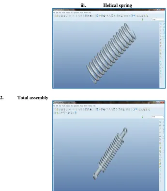
iii. Helical spring
2. Total assembly
Analysis Structural Analysis using Spring Steel as spring material Material: Spring Steel
Material Properties:
Young‟s Modulus (EX): 202000N/mm2 Poisson‟s Ratio (PRXY): 0.292 Density: 0.000007820kg/mm3
i. Imported Model from Pro/Engineer
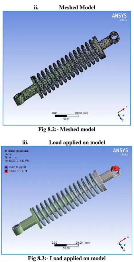
ii. Meshed Model
Fig 8.2:- Meshed model
iii. Load applied on model
Fig 8.3:- Load applied on model
iv. Results after applying load:
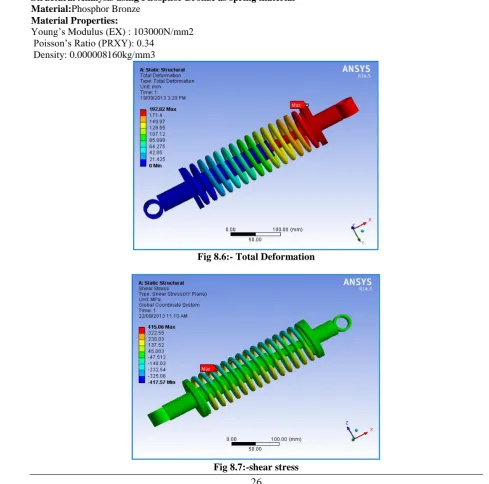
Fig 8.5:- shear stress
Structural Analysis using Phosphor Bronze as spring material Material:Phosphor Bronze
Material Properties:
Young‟s Modulus (EX) : 103000N/mm2 Poisson‟s Ratio (PRXY): 0.34
Density: 0.000008160kg/mm3
Fig 8.6:- Total Deformation
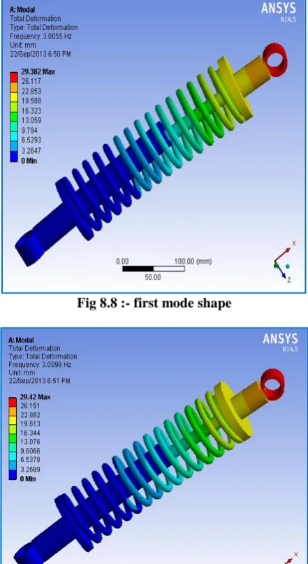
Mode Shapes for Spring Steel
Fig 8.8 :- first mode shape
Fig 8.9 :- second mode shape
Result table
Analytical Spring Steel
Phosphor Bronze Total
Deformation(mm)
111.98 113.76 192.82
Shear Stress ( N\mm2)
364 396.82 415.06
Natural Frequency
3.0055 2.1185
3.0098 2.1237
11.113 7.7306
12.873 9.0925
12.896 9.1118
17.200 12.163
IV.
CONCLUSION
1. In this project we have designed a shock absorber. We have modeled the shock absorber by using 3D parametric software Pro/Engineer.
2. To validate the strength of our design, we have done structural analysis and modal analysis on the shock absorber. We have done analysis by varying spring material Spring Steel and Phosphor Bronze.
3. By observing the analysis results, the analyzed stress values are less than their respective yield stress values. So our design is safe.
4. By comparing the results for both materials, the total deformation value is less for Spring Steel than Phosphor Bronze. So stiffness is more for Spring Steel.
5. By comparing the results for both materials, the Natural Frequency ismore for Spring Steel than Phosphor
Bronze.
6. So we can conclude that as per our analysis using material spring steel for spring is best.
REFERENCES
[1]. Mr. SudarshanMartande, Mr. Y. N. Jangale, Mr. N. S. Motagi, March 2013, “Design and Analysis of
Shock Absorber”, International Journal of Application or Innovation in Engineering and Management (IJAIEM),Volume 2, Issue 3,pp. 197-199.
[2]. Lei Lei, ZuoShuguang, Yang Xianwu, Wang Jirui, 2010,” A Finite Element Analysis of the Barrel-shaped Helical Spring on the Vehicle Rear Suspension”, IEEE International Conference on Computer Design and Applications, Volume 2, pp. 116.
[3]. VarunBrijpuria, K. K. Jain, “Analysis of Closed Coil Helical Spring Subjected to Heavy Duty”, IJEA,
Volume 1, Issue 3, pp. 52-53.
[4]. YaojungShiao, Chun-Chi Lai and Quang-Anh Nguyen, August 2010,“The Analysis of a Semi-Active
Suspension System”, SICS Annual Conference 2010,pp. 2077.
[5]. David Roylance, “Finite Element Analysis”, Feb 28, 2001, Massachusetts Institute of
Technology,Cambridge,pp.1-2.
[6]. R. S. Khurmi and J. K. Gupta, „Machine Design‟, Fourteen Edition, 2012, Eurasia Publishing House,