e
-ISSN: 2278-067X,
p
-ISSN: 2278-800X, www.ijerd.com
Volume 2, Issue 10 (August 2012), PP. 05-11
Roll Position Demand Autopilot Design using State Feedback and
Reduced Order Observer (DGO)
Parijat Bhowmick
1, Prof. Gourhari Das
2 1,2Dept. of Electrical Engg. (Control Systems), Jadavpur University, Kolkata, India
Abstract–– A Roll Position demand (as well as Roll Position Control) missile autopilot design methodology for a class of guided missile, based on state feedback, Ackermann pole-placement and reduced order Das & Ghosal observer (DGO), is proposed. The open loop unstable model of the roll control (or roll position demand) autopilot has been stabilized by using pole placement and state feedback. The non-minimum phase feature of rear controlled missile airframes is analyzed. Actuator dynamics has also been included in this design to make the overall system practically suitable for use. The overall responses of the Roll Control autopilot has been significantly improved over the frequency domain design approach where phase lag & phase lead compensator were used. Closed loop system poles are selected on the basis of desired time domain performance specifications. This set of roots not only to ensure the system damping, but also to make sure that the system can be fast. Reduced order Das & Ghosal (DGO) observer is implemented successfully in this design to estimate the Aileron angle and its rate. Finally a numerical example is considered and the simulated results are discussed in details. The date set has been chosen here for which largest rolling moment would occur (at Mach No = 4) due to unequal incidence in pitch and yaw.
Keywords–– Roll Position & Roll Rate Control Autopilot, Ailerons-Rollerons, Roll Gyro, Fin Servo Actuator, Aerodynamic control, Luenberger Observer, Das & Ghosal Observer, Generalized Matrix Inverse and Ackermann.
I.
INTRODUCTION
The fundamental objective of autopilot design for missile systems is to provide stability with satisfactory performance and robustness over the whole range of flight conditions throughout the entire flight envelope that missiles are required to operate in, during all probable engagements. Roll autopilot is used to eliminate roll Angle error caused by disturbances, and maintain stable relationship of the body coordinate system and other relative coordinates, and avoid chaos of pitch and yaw signal..
Wang Lei, Meng Xiu-yun, Xia Qun-li and Guo-Tao [1] have proposed a Roll autopilot designing method with Pole placement Method and State-Observer Feedback. State feedback gain via pole placement is designed by selecting a suitable root of closed-loop transfer function. With pole-placement method full-order state observer with one or two measurable outputs are designed respectively. In this literature, taking the integral initial values disturbance of roll angle as an example the authors have illustrated that in order to stabilize the missile’s roll angle position, not only roll angle error should be eliminated, but also the transition process of good quality is required. The quality of control system mainly depends on the distributive position of the system poles in the root plane. Pole-placement is to select state-feedback gain, and make the system poles located in expected position in root plane, so as to achieve an appropriate damping coefficient and undamped natural frequency. Only when the state parameters for feedback are observable, the pole placement method can be used. When the state parameters used for feedback are not observable or requirement of a certain filter properties, a state observer should be designed. They focused on the application of the pole placement used to design autopilot feedback gain and to design the state observer. In the design of the feedback gain, the focus is to select a set of good performance roots on the root locus. This set of roots not only to ensure the system damping, but also to make sure that the system can be fast. Through the state observer’s responses it can be seen that, when all the intermediate variables of the system are immeasurable, the observer can be designed with only one measurable output 𝛾 (Roll angle). Although the observer is the estimated means taken only when the intermediate state cannot be measured, we still can construct the intermediate state of the original system. It is concluded to the available rule: When 𝛾 and 𝛾 of the system can be measured, the system outputs of the observer with two measurable outputs can be much more accurate than that with one measurable output.
time response. The three-loop autopilot attempts to reduce the adverse effect of non-minimum phase zeros. In reference [5],
Prof. G. Das and T. K. Ghosal have derived a new method of reduced order observer construction based on Generalized Matrix Inverse theory [16] which possesses some certain advantages over the well known and well-established Luenberger observer [12] & [13]. In paper [6] & [7], the present authors discussed about the intricate details of Luenberger observer and Das & Ghosal (DGO) observer. They have also carried out an exhaustive comparison (structure-wise and performance-wise) between the two observers. In literature [11], Lin Defu, Fan Junfang, Qi Zaikang and Mou Yu have proposed a modification of classical three-loop lateral autopilot design using frequency domain approach. Also they have done performance and robustness comparisons between the two-loop and classical three-loop topologies.
The unique contribution of this paper is the modified design technique of Roll Position Demand (as well as Roll Position Control) autopilot in state space domain by reduced order Das & Ghosal observer based Ackermann state feedback. Full state feedback has been used to make the system stability better and to regulate all the states. Actuator dynamics which is neglected in [1] has also been taken in to account in this design. A very fast servo actuator is considered here so that the demanded roll position can be achieved quickly or it can be made zero in case of Roll Position Control autopilot. The system is designed in a very effective manner such that there is no steady state error in the output thus it can follow the commanded input exactly. More over the overshoots occurring in the Roll position response in case of frequency domain [14] design approach has been fully eliminated along with the maximum Roll rate has also come down significantly. It has been established through this paper that the aileron deflections and their rates are also reduced to a great extent which poses major issues of concern regarding structural failure of missiles.
II.
STATE OBSERVER
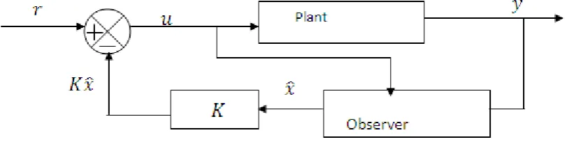
To implement state feedback control [control law is given by 𝒖 = 𝒓 − 𝑲𝒙 … … (𝟐. 𝟏)] by pole placement, all the state variables are required to be feedback. However, in many practical situations, all the states are not accessible for direct measurement and control purposes; only inputs and outputs can be used to drive a device whose outputs will estimate the state vector. This device (or computer program) is called State Observer. Intuitively the observer should have the similar state equations as the original system (i.e. plant) and design criterion should be to minimize the difference between the system output 𝒚 = 𝑪𝒙 and the output 𝒚 = 𝑪𝒙 as constructed by the observed state vector 𝒙. This is equivalent to minimization of 𝒙 − 𝒙. Since 𝒙 is inaccessible, 𝒚 − 𝒚 is tried to be minimized. The difference 𝒚 − 𝒚 is multiplied by a gain matrix (denoted by M) of proper dimension and feedback to the input of the observer. There are two well-known observers namely – Luenberger Observer[12] & [13] and Das & Ghosal Observer [5] while the second one has some genuine advantages over the first one. Das & Ghosal Observer construction procedure is essentially based on the Generalized Matrix Inverse Theory and Linear space mathematics.
Fig - 2.1: General Block Diagram of an Observer based State Feedback Control System
III.
DEVELOPMENT OF MODIFIED ROLL POSITION DEMAND AUTOPILOT FROM
THE CONVENTIONAL ONE
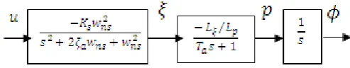
The following block diagram (fig. 3.1) represents the transfer function model of a Roll Position Control Autopilot. The model has been taken from Garnell & East [14].
Fig - 3.1: Conventional Roll Position Control (or Roll Position Demand) Autopilot
Fig – 3.2: State Feedback Design of Roll Control Autopilot using Das & Ghosal Observer (DGO)
Notations & Symbols used:
𝝓 𝑖𝑠 𝑅𝑜𝑙𝑙 𝐴𝑛𝑔𝑙𝑒; 𝒑 𝑖𝑠 𝑅𝑜𝑙𝑙 𝑟𝑎𝑡𝑒; 𝑳𝝃 𝑖𝑠 𝑅𝑜𝑙𝑙 𝑀𝑜𝑚𝑒𝑛𝑡; 𝑳𝒑 𝑖𝑠 𝐷𝑎𝑚𝑝𝑖𝑛𝑔 𝐷𝑒𝑟𝑖𝑣𝑎𝑡𝑖𝑣𝑒 𝑖𝑛 𝑅𝑜𝑙𝑙 ;
𝝃 𝑖𝑠 𝐴𝑖𝑙𝑒𝑟𝑜𝑛 𝑑𝑒𝑓𝑙𝑒𝑐𝑡𝑖𝑜𝑛 𝑎𝑛𝑔𝑙𝑒; 𝝃 𝑅𝑎𝑡𝑒 𝑜𝑓 𝐴𝑖𝑙𝑒𝑟𝑜𝑛 𝐷𝑒𝑓𝑙𝑒𝑐𝑡𝑖𝑜𝑛; 𝑻𝒂𝑖𝑠 𝐴𝑖𝑟𝑓𝑟𝑎𝑚𝑒 𝑇𝑖𝑚𝑒 𝑐𝑜𝑛𝑠𝑡𝑎𝑛𝑡; 𝒘𝒏𝒔 𝑖𝑠 𝑛𝑎𝑡𝑢𝑟𝑎𝑙 𝑓𝑟𝑒𝑞𝑢𝑒𝑛𝑐𝑦 𝑜𝑓𝐴𝑐𝑡𝑢𝑎𝑡𝑜𝑟;
𝜻𝒂 𝑖𝑠 𝑑𝑎𝑚𝑝𝑖𝑛𝑔 𝑟𝑎𝑡𝑖𝑜 𝑜𝑓 𝑎𝑐𝑡𝑢𝑎𝑡𝑜𝑟; 𝑲𝒔 𝑖𝑠 𝑡𝑒 𝑆𝑒𝑟𝑣𝑜 𝑔𝑎𝑖𝑛; 𝑲𝒈𝑖𝑠 𝑅𝑎𝑡𝑒 𝐺𝑦𝑟𝑜 𝑔𝑎𝑖𝑛;
𝝓𝒅𝐷𝑒𝑚𝑎𝑛𝑑𝑒𝑑 𝑅𝑜𝑙𝑙 𝑃𝑜𝑠𝑖𝑡𝑖𝑜𝑛; 𝑴 𝑖𝑠 𝑀𝑎𝑐 𝑁𝑢𝑚𝑏𝑒𝑟; 𝑨 𝑖𝑠 𝑅𝑜𝑙𝑙 𝑀𝑜𝑚𝑒𝑛𝑡 𝑜𝑓 𝐼𝑛𝑒𝑟𝑡𝑖𝑎;
IV.
STATE VARIABLE MODELING OF ROLL POSITION DEMAND AUTOPILOT
The open loop model of Roll Position Autopilot is shown in fig. 4.1
𝑥 1= 𝑥2… … 4.1
𝑥 2= − 1 𝑇𝑎
𝑥2− 𝐿𝜉 𝑇𝑎𝐿𝑝
𝑥3… … (4.2)
𝑥 3= 𝑥4… … (4.3)
𝑥 4= −2𝜁𝑎𝑤𝑛𝑠𝑥4− 𝑤𝑛𝑠2𝑥3− 𝐾𝑠𝑤𝑛𝑠2𝑢 … … (4.4)
So the A, B, C matrices take the forms as:
A =
0 1 0 0
0 −1
Ta
− 𝐿𝜉 𝑇𝑎𝐿𝑝
1
0 0
0 0
0 −𝑤𝑎2
1 −2ζawa
; B = 0 0 0 −𝐾𝑠𝑤𝑎2
;
and C= 1 0 0 0
0 1 0 0 … … (4.5)
The combined system (fig. 3.2) is governed by the following equations:
𝑥 = 𝐴𝑥 + 𝐵𝑢; 𝑦 = 𝐶𝑥 … … (4.6)
𝑢 = 𝑟 − 𝐾𝑥 … … (4.7)
V.
REDUCED ORDER DAS & GHOSAL OBSERVER (DGO) – GOVERNING
EQUATIONS
Reduced order Das and Ghosal observer [5] is governed by the following equations and conditions.
𝑥 = 𝐶𝑔𝑦 + 𝐿 … … … (5.1 ) (eqn. 13 of [5])
(𝑡)= 𝐿𝑔𝐴𝐿 𝑡 + 𝐿𝑔𝐴𝐶𝑔 𝑦 𝑡 + 𝐿𝑔 𝐵 𝑢 𝑡 … … … (5.2) (eqn. 15 of [5])
𝑦 = 𝐶𝐴𝐿 + 𝐶𝐴𝐶𝑔 𝑦 + 𝐶𝐵 𝑢 … … (5.3) (eqn. 18 of [5])
= 𝐿𝑔𝐴𝐿 − 𝑀𝐶𝐴𝐿 + 𝐿𝑔𝐴𝐶𝑔− 𝑀𝐶𝐴𝐶𝑔 𝑦 + 𝐿𝑔− 𝑀𝐶𝐵 𝑢 + 𝑀𝑦 … … (5.4) (eqn. 19 of [5])
𝑞 = 𝐿𝑔𝐴𝐿 − 𝑀𝐶𝐴𝐿 𝑞 + 𝐿𝑔𝐴𝐶𝑔− 𝑀𝐶𝐴𝐶𝑔 + 𝐿𝑔𝐴𝐿 − 𝑀𝐶𝐴𝐿 𝑀 𝑦 + 𝐿𝑔− 𝑀𝐶𝐵 𝑢 … … (5.5) (eqn. 20 of [5])
𝑤𝑒𝑟𝑒 𝑞 = − 𝑀𝑦 … … (5.6) (Page-374 of [5])
Equation (5.5) can be expressed in short form: 𝑞 = 𝐴 𝑞 + 𝐽 𝑦 + 𝐵 𝑢 … … (5.7)
𝐴𝑛𝑑 𝑥 = 𝐿𝑞 + (𝐶𝑔+ 𝐿𝑀)𝑦 … … 5.8 (eqn. 21 of [5])
Equation (5.8) can also be expressed in short form: 𝑥 = 𝐶 𝑞 + 𝐷 𝑦 … … (5.9)
Then equation (4.6) can be rewritten by using eqns. (4.7) & (5.9) as:
𝑥 = 𝐴 − 𝐵𝐾𝐷 𝐶 𝑥 + 𝐵𝑟 − 𝐵𝐾𝐶 𝑞 … … (5.10)
Equation (5.7) can be rewritten by using eqns. (4.7) & (5.9) as:
𝑞 = 𝐽 − 𝐵 𝐾𝐷 . 𝐶𝑥 + 𝐵 𝑟 + 𝐴 − 𝐵 𝐾𝐶 𝑞 … … (5.11)
Combining eqns. (5.10) and (5.11) into a matrix, we get
𝒙 𝒒 =
𝑨 − 𝑩𝑲𝑫 𝑪 −𝑩𝑲𝑪
𝑱 − 𝑩 𝑲𝑫 𝑪 𝑨 − 𝑩 𝑲𝑪 𝒙 𝒒
+ 𝑩𝑩 𝒓 … … 𝟓. 𝟏𝟐 𝒂 𝑎𝑛𝑑
𝒂𝒏𝒅 𝒙 = 𝑪 𝒒 + 𝑫 𝒚 = 𝑪 𝒒 + 𝑫 𝑪𝒙 … … 𝟓. 𝟏𝟐 𝒄 .
VI.
SIMULATION RESULTS
The following numerical data for a class of guided missile have been taken for Matlab simulation:
𝑇𝑎 = 0.0257 𝑠𝑒𝑐; 𝐿𝜉= −13500; 𝐿𝑝= −37.3
𝐾𝑠 = −1.48; 𝐾𝑔= 1; 𝑤𝑛𝑠 = 180 𝑟𝑎𝑑
𝑠𝑒𝑐; 𝜁𝑎= 0.6; 𝑀 = 2.8; 𝐴 = 0.96;
Using these values, the open loop state space model of three-loop autopilot [given by eqns. (1) & (2)] becomes,
𝑥 1 𝑥 2 𝑥 3 𝑥 4
=
0 1 0 0
0 −38.9105 −14083 0
0 0 0 0 0 −32400 1 −216 𝑥1 𝑥2 𝑥3 𝑥4 + 0 0 0 −47952
𝑢 … … 6.1 𝑎 𝑎𝑛𝑑
𝑦 = 1 0 0 0
0 1 0 0
𝑥1 𝑥2 𝑥3 𝑥4
… … (6.1 𝑏)
Open loop poles of the system: 𝑷 = 0 −38.91 −108 + 𝑗144 −108 − 𝑗144
Desired closed loop system poles taken: 𝑷𝒅𝒆𝒔𝒊𝒓𝒆𝒅= −300 + 𝑗250 −300 − 𝑗250 −72 −61
Desired observer poles taken:𝑶𝒃 = −1740 −1800
State Feedback Gain matrix is given by using Ackermann’s formula:
𝑲 = 0.9918 0.0219 −3.6971 −0.0100
Observer Gain matrix is also obtained by using Ackermann’s formula: 𝑴 = 0 −0.2360
0 −169.1141
In the design of Das & Ghosal observer L matrix has been chosen from the linearly independent columns of (𝐼4×4− 𝐶𝑔𝐶) matrix.
𝐼4×4− 𝐶𝑔𝐶 =
0 0 0 0
0 0 0 0
0 0 0 0 1 0 0 1 𝑠𝑜 𝑡𝑒 𝐿 𝑚𝑎𝑡𝑟𝑖𝑥 𝑐𝑎𝑛 𝑏𝑒 𝑓𝑜𝑟𝑚𝑒𝑑 𝑎𝑠 𝐿 = 0 0 0 0 1 0 0 1 ;
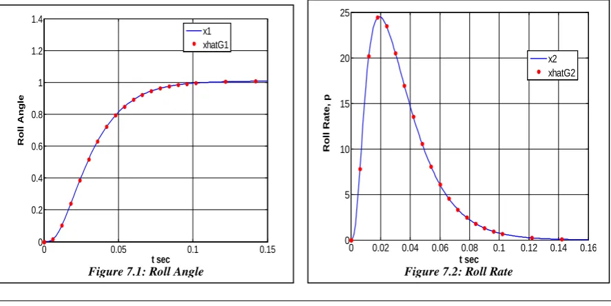
Finally unit step simulation is done on the combined model (i.e. Roll Position Demand Autopilot + DGO + state feedback), given by matrix eqns. (5.12a), (5.12b) & (5.12c), by using Matlab software (version 7.12, 2012a) and the results obtained, are presented below:
N.B: In all of the above four graphs the blue lines indicate the original states of the Roll Position Demand Autopilot and the
red starred lines indicate the estimated states by reduced order Das & Ghosal observer (DGO)
VII.
OBSERVATIONS AND DISCUSSIONS
It can be readily inferred that the overall responses are improved and very much satisfactory. The Roll position demand is met exactly without any steady state error. No oscillations or peak is observed. Moreover within 0.1 second it has reached the steady level which is a very graceful performance. Aileron deflections are seen to be very low. It has also come down to zero within only 0.04 seconds. It is established through the simulation that Das & Ghosal observer has successfully caught the system states within less than 0.02 seconds and that also without any steady state error or oscillations. Further the experiments have also been carried out on the very well known and well used Luenberger observer [12] & [13] in place of Das & Ghosal [5] and it is seen that Luenberger observer will work only when the C matrix lies in the standard form 𝐼 ⋮ 0 otherwise not. Like here C matrix is in the standard form. Otherwise it will require an additional coordinate transformation to bring back the C matrix in the standard form and then only Luenberger observer will succeed. This is a one of the greatest advantages [6], [7] of Das & Ghosal observer over Luenberger. In the simulation and actual practice in the system it should be considered to combine with the difficulty of measuring the variables and the measurement accuracy requirements, in order to choose the proper root to meet the engineering requirements.
VIII.
ACKNOWLEDGEMENT
I would like to thank my friend Sanjay Bhadra, Electrical Engg. Dept, Jadavpur University, for his constant support and motivation.
REFERENCE AND BIBLIOGRAPHY
[1]. Wang Lei, Meng Xiu-yun, Xia Qun-li and Guo Tao, “Design of Autopilot with Pole Placement and State-Observer feedback”, published in IEEE International Conference on Computer Science and Automation Engineering (CSAE), Vol. 4, pp. 53-56, June 2011
[2]. Gourhari Das, K. Dutta, T K. Ghosal, and S. K. Goswami, “Structured Design Methodology of Missile Autopilot ”, Institute of Engineers (I) journal – EL, Kolkata, India, November. pp 49-59 1996.
[3]. Gourhari Das, K. Dutta, T. K. Ghosal, and S. K. Goswami, “Structured Design Methodology of Missile Autopilot – II”, Institute
of Engineers (I) journal – EL, Kolkata, India, November, vol 79 pp.28-34, 1998
[4]. Gourhari Das, K. Dutta, T. K. Ghosal, and S. K. Goswami, “Structured Linear Design Methodology for Three-Loop Lateral Missile Autopilot”, Institute of Engineers (I) journal, EL-1, Kolkata, India, February, vol 85 pp 231-238, 2005
[5]. Gourhari Das and T.K. Ghosal, “Reduced-order observer construction by generalized matrix inverse”, International Journal of Control, vol. 33, no. 2, pp. 371-378, 1981.
[6]. Parijat Bhowmick and Dr Gourhari Das, “Application of Das & Ghosal Observer and Comparison between Reduced Order Luenberger and Reduced Order Das & Ghosal Observer”, Proceedings of RITS-International Conference On Advancements In Engineering & Management (RITS ICAEM), pp. 1-8, Hyderabad, February 2012
[7]. Parijat Bhowmick and Dr. Gourhari Das, “A Detailed Comparative Study between Reduced Order Luenberger and Reduced Order Das & Ghosal Observer and their Applications” Proceedings of the International Conference in Computer, Electronics and Electronics Engineering, pp. 154 – 161, Mumbai, March 2012, doi:10.3850/978-981-07-1847-3 P0623.
[8]. Parijat Bhowmick and Dr. Gourhari Das, “Reduced Order Observer (DGO) based State Variable Design of Two Loop Lateral
Missile Autopilot in Pitch Plane”, International Journal of Engineering Research and Development (IJERD), to be published in June issue, 2012
[9]. Parijat Bhowmick and Dr. Gourhari Das, “Three loop Lateral Missile Autopilot Design in Pitch Plane using State Feedback &
Reduced Order Observer (DGO)”, International Journal of Engineering Research and Development (IJERD), to be published in June issue, 2012
[10]. Wen Qui-qiu, Xia Qun-li and Cai chun-tao, “Study on Autopilot PI Compensator Optimal Parameter Design with Phase Lag
Constrain”, published in International IEEE Conference on Intelligent Computing and Intelligent Systems (ICIS), Vol. 1, pp. 865 – 869, October 2010.
Figure 7.3: Aileron Deflection
0 0.02 0.04 0.06 0.08 0.1
-0.25 -0.2 -0.15 -0.1 -0.05 0 0.05 0.1 t sec A il e r o n D e fl e c ti o n , G y e x3 xhatG3
Figure 7.4: Rate of Aileron Deflection
0 0.01 0.02 0.03 0.04 0.05 0.06
[11]. Lin Defu, Fan Junfang, Qi Zaikang and Mou Yu, “Analysis and improvement of missile three-loop autopilots”, Journal of Systems Engineering and Electronics, vol. 20, No. 4, pp. 844-851, 2009
[12]. D.G. Luenberger, “An Introduction to Observers”, IEEE Transactions on Automatic Control, vol. AC-16, no. 6, pp. 596-602,
December. 1971.
[13]. D.G. Luenberger, “Observing the states of a linear system”, IEEE Transactions Mil. Electron. vol. MIL-8, pp. 74-80, April. 1964.
[14]. P. Garnell and D. J. East, “Guided Weapon Control Systems”, Pergamon press, 1977