PERFORMANCE COMPARISON OF MOVING RELAY NODES IN
LTE-ADVANCED (LTE-A)
Anirudh Goel1, Varun Jain2
1.INTRODUCTION
In order to achieve the requirements of the next generation the 3rd Generation Partnership Project (3GPP) working towards the development of the LTE. While the key goals for this evolution are increased data rate, improved spectrum efficiency, improved coverage and reduced latency. The end results of these goals are significantly improving service provisioning and reduction of operator costs for different traffic scenarios. The requirements for LTE-Advanced are agreed and the radio interface techniques are currently under discussion.
One of the most important requirements for LTE Advanced is to support LTE and enhancement in the frequency spectrum. Layered OFDM radio access is used to attain higher level requirements such as system performance and full backward compatibility.
Relay deployment, which is an integral part of LTE-Advanced, is used to enhance capacity, extend cell coverage area and increase the overall throughput of the network [1-2]. Relaying technology has been considered as one of the advanced features of LTE-Advanced. Relays are integral part of the next generation of mobile broadband communication systems [3, 4]. Moreover, relays are expected to be a viable cost efficient solution for replacement of base stations [6, 7].One of the requirements for successful deployment of relay stations in cellular networks is the understanding of network coverage areas. Prediction of the path loss is a fundamental task in cellular systems deployment. To accomplish this task, engineers rely on propagation modelling that estimates the average signal strength and consequently the path loss on the link between a base station (i.e. eNodeB) and a relay station. There is a number of relay propagation models. They have been suggested by 3GPP [2], WINNER (Wireless World Initiative New Radio) [8]. However, models in [2, 8] were derived for only one level of relay antenna height, namely 5 m and 15 m respectively, and therefore their applicability for multiple relay heights still needs to be studied. To the best of author's knowledge, very view studies evaluate the path loss on the eNodeB-relay link for different relay heights. The study in [9] investigates the impact of the relay height in WINNER models. Results of [9] show a mismatch between measurements and WINNER B5f model. The research in [10] describes and documents measurement campaign which was set up specifically to examine the path loss on eNodeB-relay link. Even though an empirical propagation model for relaying scenarios is proposed, the study does not provide any comparison with other existing models.
When deployed, a multi-hop relaying system consists of two links. The first link is the link between the eNodeB and the relay and it is referred to as the backhaul link. The second link is the link between the relay and the end user and it is referred to as the access link. The study presented in this paper focuses on the path loss encountered on eNodeB-relay link only. The validity of different propagation models is examined by comparing their predictions with measurements. Additionally, since many propagation models are already coded and are part of software packages it is of special interest to establish a relationship between measurements and some of these standard propagation models. Well known examples of
1 StudentECE Department, Northern India Engineering College, New Delhi, India
2 Assistant Professor, ECE Department, Northern India Engineering College, New Delhi, India
Abstract:With the day by day increasing demand and rapid development of wireless communication quality during the past thirty years, the initial 1G have run into 4G with a higher data rate and a better mobility support. The 4G technique, International Mobile Telecommunications-Advanced (IMT-Advanced) systems are mobile broadband communication systems include new features that go significantly beyond those of the 2000. The key or we say major requirements of IMT-Advanced systems include increased spectral efficiency and bandwidth, improved cell edge performance and mobility support, reduced Control and User plane latency, reduced handover interruption time. The mobility support can be achieved with the help of moving relay nodes. Mobile relay node is a dedicated network node equipped on the vehicles, e.g. buses and trains, to provide a fixed access link to passengers riding on vehicles. Therefore, mobile relay is very suitable to solve the capacity gain of high speed vehicles if it is well deployed. Vehicular penetration loss plays a vital role in the implementation of MRNs. In this paper, we have analysed the performance of MRNs in terms of vehicular penetration loss and path loss for various pathloss models for different height of receiver antenna.
Keywords:Relay Nodes (RN); Moving Relay Nodes (MRN); Long Term Evolution (LTE);Long Term Evolution- Advanced (LTE-A); Vehicle Penetration Loss (VPL); User Equipment (UE) and Base Station (BS).
the standard models are: Hata-Okumura, Lee model, COST 231-Hata, COST 231 Walfisch-Ikegami, and many proprietary models. Application of standard models for modelling relay scenarios is handled through addition of appropriate correction factors[5].
2. MOVINGRELAYNODES
In this part we show the potential of moving relay nodes (MRNs). Consider a single cell noise limited system where the transmission is corrupted by flat Rayleigh fading. Assume the interference from neighbouring cells is removed by certain interference coordination and interference cancellation (ICIC) schemes. Assume the MRNs are mounted on top of public transportation vehicles and show that by using MRNs, the capacity, reliability and coverage for vehicular user in future wireless networks can be improved significantly. To this end, we study and compare the performance of dual-hop MRN assisted transmission, dual-hop transmission assisted by a fixed relay node (FRN) deployed on the street, as well as of the baseline single-hop direct transmission.
In order to achieve an accurate and fair comparison between the use of FRN and MRN, we optimize the FRN position in terms of minimizing outage probability (OP) at the UE side. This position is a function of the path loss, transmit power and vehicle penetration loss (VPL). In addition, the analytical results for the OP are verified by Monte-Carlo simulations. We also evaluate the ergodic capacity of the considered schemes. We show that as the VPL increases, for vehicular UEs, the MRN assisted transmission outperforms the conventional single-hop as well as the FRN assisted scheme. Hence using MRNs for vehicular UEs is very promising for future wireless system
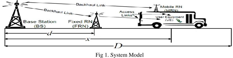
Fig 1. System Model
As depicted in Fig 1, we consider a scenario where the BS has fixed coverage of meters. One vehicle is moving along a highway with an UE inside it. For RN assisted transmission, i.e., both MRN and FRN assisted transmission; we always assume a dual-hop transmission where the BS transmits to a vehicular UE via an RN. Following the 3GPP convention, the link between the BS and the MRN or FRN is named as the backhaul link and the link between the RN and the UE as the access link.
3. VEHICULARPENETRATIONLOSS
Currently, a significant number of mobile users are vehicular, i.e. they use wireless broadband while riding public transportation vehicles. Moreover, it is expected that the number of vehicular users will greatly rise due to the high penetration of smartphones and the increasing portability of laptops. Hence public vehicles are expected to evolve into wireless hotspots. A significant problem, however, is that radio signals travelling from the BS into the vehicle are severely attenuated by the vehicular penetration loss (VPL). Measurements show that VPL can be as high as 25 dB in a minivan at the frequency of 2.4 GHz. Higher VPLs are foreseeable in the well isolated vehicles of interest here, and in higher frequency bands, e.g. the 3.6 GHz band allocated to next generation mobile communication. In order to meet the quality-of-service (QoS) requirement for a user equipment (UE) inside a vehicle, more radio frequency (RF) power needs to be transmitted to compensate the VPL, which can boost the energy consumption. As vehicular UEs (VUEs) will represent a significant portion of broadband UEs in the near future, it is crucial to design wireless systems in a way that minimizes the energy consumption while guaranteeing required QoS for these VUEs.
4.PATHLOSSMODEL
Path loss is the reduction in power density (attenuation) of an electromagnetic wave as it propagates through space. Path loss is a major component in the analysis and design of the link budget of a telecommunication system. This term is commonly used in wireless communications and signal propagation.
3GPP Model: Third Generation Partnership Project suggests several propagation models for predicting path loss at 2 GHz band. Among the suggested models there is a model dedicated to eNodeB relay links [5]. For non-line of sight scenarios, the path loss is given as:
PL3GPP = 125.2+ 36.3 log (d) (1)
Where d in Kilometre (Km) is the eNodeBrelay separation.
model for fixed relays (i.e., stationary feeders), namely the scenario B5. This scenario is further divided into five sub-scenarios according to the relay location as it .WINNER B5f sub-scenario is the most appropriate channel model for prediction of the path loss on the link between base station (i.e. eNodeB) and relay station [5]. WINNER B5f model takes into account both LOS and NLOS conditions where the base station antenna height is above the rooftop level and the relay
station antenna height is either above or below the rooftop level.
WINNER B5f model is given by:
PLWINNER = 57.5 +23.5log(d)+ 23log(f/5) (2)
Whered in metre (m) is the distance (30 m <d< 1.5 Km) and f in GHz is the frequency (2 GHz <f< 6 GHz).
COST 231-Hata Model:The European Cooperative for Scientific and Technical research (EURO-COST) established the COST-231 working committee to introduce COST-231 model which is considered as an extended version of Hatamodel to frequencies up to 2 GHz [5]. The model is widely used for prediction of the median path loss in mobile wireless systems and its formula is given by:
PLCOST231HATA = A+ B log(d)+ Cm–a (hm) (3)
A = 46.3+ 33.9log(f) − 13.82 log(hb) (4)
B = 44.9 −6.55 log(hb) (5)
where f is the frequency in Mega Hertz (MHz), hb, hm are the transmitter antenna height and the receiver antenna height in
[m], respectively, d denotes the transmitter-receiver separation in (Km)[5]. For small to medium cities:
𝑎(ℎ𝑚)=(1.1log(𝑓)−0.7)ℎ𝑚−(1.56log(𝑓)−0.8) (6)
For large cities:
a (hm)= (7)
LEE MODEL: Lee model is one of the most popular and widely used path loss models. It is known for its simplicity along with its reasonable prediction accuracy. Lee model was initiallyderived for frequencies around 900 MHz Later on, the model was extended to frequencies up to 2 GHz. The path loss form of the model is provided relative to reference conditions and is given a:
PLLEE= PL0+ m log(d/d0) - HT - HR (8)
HT= 15log(HT/HT ref) (9)
HR= 15log(HR/HR ref) (10)
PL0 is a path loss at reference distance (d0) in dB, m is a slope in dB/decade, d is a transmitter-receiver separation in Km, d0is
a reference distance (1.609 Km), Htis a transmitter antenna height in metre, Htref is a reference transmitter antenna height
(30.48 m), Hris a receiver antenna height in metre, Hrrefis a reference receiver antenna height (3.048 m) [5].
Table 1. Path loss Parameters of LEE model
Path Loss (PL0) PL0 (dB) m (dB/decade)
Open area 95 43.5
Sub urban 107.7 38.4
Urban(Philadelphia) 116 36.8
Urban (Newark) 110 43.1
ERICSSON MODEL: This path loss model was created by Ericsson for use in network planning and deployment process of mobile communication network. Ericsson model also stands on the modified Okumura-Hata model to allow room for changing in parameters according to the propagation environment [11]. Path loss according to this model is given by:
PL0 = a0 + a1 log10(d) + a2 log10(hbs) + a3 log10(hbs) log10(d)-3.2 (log10(11.75hm)) 2
+ g(f) (dB)(11)
Whereg(f) is
g(f) = 44.49 log10 (f) – 4.78(log10 (f))2 (12)
Wheref is the frequency in MHz, d is the distance between the base station and the mobile station in Km, hbs is the base
station antenna height and hms is mobile station antenna height in metre.
Table 2. Pathloss Parameter of Ericsson Model
Suburban 48.2 68.93 -12 0.1
Urban 36.2 30.2 -12 0.1
5.FRN,MRN AND DIRECTTRANSMISSION
Fixed relay nodes (FRNs) can improve the energy efficiency of wireless networks, as properly deployed FRNs can effectively compensate path loss. However, as FRNs are deployed on the street level, they cannot combat VPL that attenuates received signals at vehicular UEs. An effective way to combat VPL is through the deployment of moving relay nodes (MRNs) on top of public transportation vehicles. MRNs consist of outdoor and indoor antenna units. The indoor antenna is inside the vehicle communicating with the vehicular UEs, while the outdoor antenna is outside the vehicle communicating with the BS, hence the VPL is circumvented. MRNs can also provide other benefits such as group handover, and collective channel state information (CSI) feedback. Preliminary studies have shown the potential capacity and coverage improvement of using coordinated and cooperative MRNs on top of trains. It is shown that MRNs can improve the spectral efficiency and lower the outage probability (OP) when the average transmits power of the BS and the relay node is fixed. However, none of the aforementioned contributions studies the benefit of MRNs from an energy efficiency point of view. The FRN assisted transmission, when the relay node position is optimized, can provide significant gains in terms of energy consumption. Moreover, as the VPL increases, both FRN and MRN assisted transmission can significantly lower the overall transmit energy compared to the direct transmission. The use of MRN outperforms FRN assisted transmission when VPL is moderate to high.
6. RESULT AND DISCUSSION
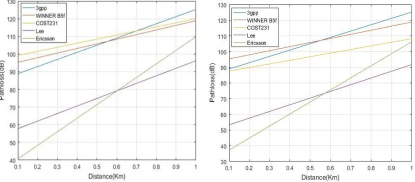
The Fig 2 to 10 representing path loss for various path loss models v/s distance between the relay node and the base station show the following results:
Fig 2. Comparison of models in suburban h=4m Fig 3. Comparison of models in suburban h=8m
Fig 6. Comparison of model in urban(network) h=8m Fig 7. Comparison of model in urban(network) h=16m
Fig 8. Comparison of model in urban(Philadelphia) h=4mFig 9. Comparison of model in urban(Philadelphia) h=8m
Fig 10. Comparison of model in urban (Philadelphia) h=16m Fig 11. Comparison of FRN, Direct Transmission and MRN
The validity of models is examined by comparing their path loss prediction to the measurements. While no particular parameters for 3GPP and WINNER B5f models need to be defined, following assumptions were made for the other two models in this study. "Suburban environment, urban (Newark) and urban (Philadelphia)" categories with receiver antenna height correction factor a(hm) for small to medium city was used for the case of COST231-Hata model. Finally,
The Fig 11 representing VPL for direct transmission, fixed relay nodes and moving relay nodes shows that vehicular penetration loss is maximum for direct transmission which reduces on deploying fixed relay nodes and is least with the deployment of moving relay nodes.
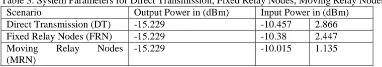
Table 3gives idea about VPL comparison for different scenarios.
Table 3: System Parameters for Direct Transmission, Fixed Relay Nodes, Moving Relay Nodes
Scenario Output Power in (dBm) Input Power in (dBm)
Direct Transmission (DT) -15.229 -10.457 2.866
Fixed Relay Nodes (FRN) -15.229 -10.38 2.447
Moving Relay Nodes
(MRN)
-15.229 -10.015 1.135
7. CONCLUSION
The Simulations for Pathloss for various Pathloss models for different height of receiver antenna were done. It was observed that the path loss is a linear function of the log of the distance. Another observation was that there is a clear trend of decreasing path loss values with the increase of the receiver antenna height. Vehicular penetration losses were also simulated for direct transmission, fixed relay node and moving relay node to analyse the performance of moving relay nodes. It was observed that VPL is maximum for direct transmission and is least in case of moving relay nodes. Hence, the deployment of moving relay nodes is surely a solution to improve the existing communication system.
8.REFERENCE
[1]. A. So, B. Liang. Effect of relaying on capacity improvement in wireless local area networks, In Proceedings of IEEE Wireless Communications Networking Conference, 2005 IEEE, Vol. 3, New Orleans, USA, 13-17 March 2005.
[2]. 3GPP, TR 36.814 V9.0.0: Further advancements for E-UTRA physical layer spects (Release 9), 2010-03.
[3]. Y. Yang, H. Hu, J. Xu, G. Mao. Relay technologies for 126 Path Loss Models for LTE and LTE-A Relay Stations WiMAX and LTE-Advanced mobile systems, IEEE Commun. Mag., vol. 47, no. 10, pp. 100-105, Oct. 2009.
[4]. R. Schoenen, W. Zirwas, B. H. Walke. Capacity and coverage analysis of a 3GPP-LTE multi-hop deployment scenario, Proc. IEEE ICC 2008, pp. 31-36, Beijing, China, May 2008.
[5]. MasoudHamid, IvicaKostanic,Path Loss Models for LTE and LTE-A Relay Stations, Universal Journal of Communications and Network 1(4): 2013,pp.119-126.
[6]. M. Werner, M. Naden, P. Jesus, C Silva, P. Moberg, P. Skillermark, W. Warzanskyj. Cost Assessment and Optimization Methods for Multi-Node Radio Access Networks, IEEE Vehicular Technology Conference (VTC) spring, 2008, pp. 2601-2605.
[7]. P. Moberg, P. Skillermark, N. Johansson, A. Furuskär. Performance and cost evaluation of fixed relay nodes in future wide area cellular networks, In Proceedings of IEEE 18th International Symposium on Personal, Indoor and Mobile Radio Communications,2007, Athens, Greece, pp. 1–5, 3-7 September 2007.
[8]. J. M. P. Kyösti, L. Hentilä, X. Zhao. WINNER II Channel Models, IST-4-027756 WINNER II, D1.1.2 V1.0, September 2007.
[9]. C. QuangHien, J.-M. Conrat, J.-C. Cousin. On the impact of receive antenna height in a LTE-Advanced relaying scenario, 2010 European Wireless Technology Conference (EuWIT), pp. 129-132, 2010.
[10].M. Hamid, I. Kostanic. Path Loss Measurements for Relay Stations in 1900MHz Band, accepted for publication in World Congress on Engineering and Computer Science 2013 (WCECS 2013), San Francisco, USA, 23-25 October, 2013.