IJIRT 146854
INTERNATIONAL JO URNAL OF INNOVATIVE RESEARCH IN TECHNOLOGY964
Sensor-less Vector speed Control of Induction motor
Drives using MRAS technique
Miss. Supriya A. Pande
1, Prof. Mrs. Aishwarya A. Apte
21,2
Electrical Engineering Department, AISSMS COE, Pune, Maharashtra
Abstract-A model reference adaptive system (MRAS ) is simplest speed estimate technique for controlling induction motor from very low to very high speed range. A reference and adaptive model is used to generate two speeds Nr and Nr*, and its error used to control speed as per requirement. This paper presents a new sensor-less vector control scheme consisting on the one hand of a speed estimation algorithm which overcomes the necessity of the speed sensor and on the other hand two different models with the simplest algorithm. In this work, an indirect field-oriented induction motor drive with a MRAS is presented. The design includes rotor speed estimation from measured stator terminal voltages and currents. The estimated speed is used as feed-forward in an indirect vector control system achieving the speed control without the use of shaft mounted transducers with adaptive control. A MATLAB demonstration is done for a high performance of the control scheme under load disturbances and other parameter uncertainties. In order to model and simulate the electrical system, the simulation software S imulink is used.
Index Terms-S ensorless, Vector control, indirect field oriented control, Induction motor, MRAS .
I. INTRODUCTION
The field of ac drives has experienced an explosive growth in recent years and its demand reaches at the peak as additional services are being added to existing infrastructure. The control and estimation of induction motor drives constitute a vast subject, and the technology has further advanced in recent years. Induction motor drives with cage type machines have been the workhorses in industry for variable speed application such as includes pumps and fans, paper and textile mills, subway and locomotive propulsion, electric and hybrid vehicles etc. The control and estimation of ac drives in general are considerably more complex than thos e of dc drives. Vector control
is efficient and effective way of controlling speed of 3phase Induction motor drive [1-6].
An indirect vector control of induction motor is a feed-forward control here a motor speed is estimated using various techniques from motor terminal voltages and current. A speed sensor is eliminated due to finite number of limitations such as prone to noise, shaft mounting arrangement, expensive etc. The induction motor is most widely used motor, and in varied applications a desire for high dynamic performance in wide speed range is necessity. The sensorless vector control with speed estimation techniques is the best solution for this situation. The simple yet robust control is another basic need. Thus, MRAS system is boon having two controllers with easiest algorithm.
In recent literature, many researchers have carried out the design of sensorless vector of IM drives based on the Model reference Adaptive Scheme, Extended Kalman Filter, Luenberger Observer, also Artificial Neural Network [7-14].
This paper presents the Model reference adaptive system (MRAS) for sensorless speed control using MATLAB simulations, and results for various speed and torque is discussed. MATLAB Simulink software is used for simulation of this model.
II. MODEL REFERENCE ADAPTIVE SYSTEM
IJIRT 146854
INTERNATIONAL JO URNAL OF INNOVATIVE RESEARCH IN TECHNOLOGY965
models of different structures to estimate the samestate variable (Wm) [16]. The structure that does not contain the variable that should be estimated, e.g. rotor speed, is considered as a reference model. However, the structure that contains the variable to be estimated is treated as an adjustable or adaptive model. The error between the outputs two controllers is used to apply suitable adaptive mechanism. The speed correctly estimated for control is defines when the error between these two controls converges to zero. The estimated speed is then equal to the actual motor speed. This adaptation is made possible with the PI controller.
Figure 1 illustrates the schematic block of a MRAS based speed estimator.
Fig.1 The schematic block of a MRAS based speed estimator.
In this block diagram ψr(r) is output of reference model, whereas ψr(a) is output of adaptive model, these are two estimates of the rotor flux space vector in stationary reference frame. The open loop voltage model is widely used as reference system because of the lack of speed in it and because of its simplicity and relatively robustness against motors variation. The reference model and adaptive model are denoted by equation (1) and (2)
s s is+ dψs
(1)
(2)
Rotor flux of induction motor drives is computed as:
[
] (3)
[ ] (4)
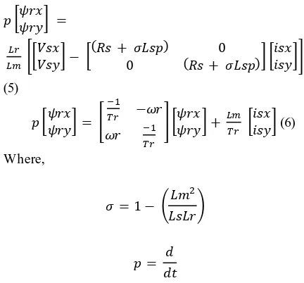
From Equations (1) a rotor flux space vector can be obtained, and as the equation is free of Rotor speed term, it is said to be Reference model. Also, a space vector of rotor flux is obtained from equations (2), where rotor speed term is present thus, it is a adaptive model. Equation (3) and (4) represents the rotor flux
space vector. By resolving equations (3) and (4) for two axis component i.e. a rotor flux vector in stationary reference frame we get the following equations:
[ ]
*[
] [
( )
( )] [ ]+
(5)
[ ] [
] [ ] [
] (6)
Where,
(
)
Also, s, Is, Ir, ψs, ψr are the stator voltage, stator and rotor current, stator and rotor flux vectors. Rs and r are stator and rotor resistance and ωm is a rotor speed.
∫
( ) ( ) ( ) ( )
These two rotor fluxes equations (5) and (6) are used for tuning the speed signal (error signal). The error signal is tuned in MRAS using simple PI controller. The adaption algorithm converge the error between two rotor fluxes to zero and so the speed control is obtained.
III. MATLAB Simulation Work
IJIRT 146854
INTERNATIONAL JO URNAL OF INNOVATIVE RESEARCH IN TECHNOLOGY966
with Gate pulse generator. Fig.2 shows the MATLABsimulation diagram for MRAS sensorless control of Induction motor drive.
Fig.2 Simulation of MRAS Sensorless vector control for Induction motor drives in MATLAB.
The 3 phase Induction motor, squirrel cage type’s speed is to be controlled under steady state and transient state. The terminal voltages and current are taken for converting to 3 phase to 2 phase component (Id and Iq). These Id and Iq are current responsible for Flux and Torque. This conversion is Clark’s transformation and vice a versa is Parks transformation. The conversions are carried out using FOC (Field oriented control) block.
The speed control block is the block which will give reference torque and reference flux from referen ce speed pre decide. These reference torque and flux (Te* and ψ*) then generate the reference Iabc to feed to Induction motor through gate signal. As the speed tuning error at FOC block is made zero using simple PI controller, the speed control is obtained.
IV.MATLAB RESULT
The control speed of induction motor drive for 500 rpm reference speed and 1000 reference torque, the control speed is obtained at 0.55 sec the motor toque is fluctuating at 650-1200 and rotor speed is maintained at 1000 rpm constant, despite of varying torque. The simulation results for the 1000 rpm speed at 1000 torque are shown in Fig.3 as below:
Fig.3 Simulation Results for 1000 torque and 1000rpm speed.
And for 500 rpm reference speed and 500 reference torque, the control speed is obtained at 0.55 sec the motor toque is maintained constant 550 and rotor speed is maintained at 1000 rpm constant. The simulation results for 1000 rpm speed at 500 torque are shown in Fig.4 as below:
Fig.4 Simulation Results for 500 torque and 1000rpm speed.
The simulation result shows the constant speed output for are variation in input torque, which shows the system is robust in steady state as well as transient conditions.
V.CONCLUSION
IJIRT 146854
INTERNATIONAL JO URNAL OF INNOVATIVE RESEARCH IN TECHNOLOGY967
drive from small to multi horsepower. The MATLABsimulation shows the constant controlled speed output for varied input torque. Hence, the MRAS system is robust in all steady state and transient conditions.
REFERENCES
[1] B.K.Bose "Modern Power Electronics And AC Drives" Easter Economy Edition.
[2] Shraddha V. Hule, Bindu R., Deepa Vincent "Sensorless Vector Control of Three Phase Induction Motor" International Conference on Advances in Communication and Computing Technologies (2014)
[3] Jingchuan Li, Longya Xu, and Zheng Zhang "An Adaptive Sliding-Mode Observer for Induction Motor Sensorless Speed Control" IEEE Trans. on Industry Application, Vol.41,No.4, JULY/AUGUST 2005
[4] Mustapha MESSAOUDI, Habib KRAIEM, Mouna BEN HAMED, Lassaad SBITA and Mohamed Naceur ABDELKRIM "A Robust Sensorless Direct Torque Control of Induction Motor Based on MRAS and Extended Kalman Filter" Leonardo Journal of Sciences 2008 [5] Mabrouk Jouili, Kamel Jarray, Yassine Koubaa
and Mohamed Boussak, "A Luenberger State Observer for Simultaneous Estimation of Speed and Rotor Resistance in sensorless Indirect Stator FOC of IM Drive" IEEE trans. Energy Conversion and vol.14,Dec 1999.
[6] R.Krishnan "Electric Motor Drives modeling, analysis, and control"
[7] Jehudi Maes and Jan A. Melkebeek "Speed sensorless direct torque controlof IM using adaptive ux observer" IEEE TRANSACTIONS
ON INDUSTRY APPLICATIONS, VOL.
36,June 2000.
[8] Tae-Sung Kwon, Myoung-Ho Shin, and Dong-Seok Hyun "Speed sensorless stator flux oriented control of IM in the _eld weakening region using Luenberger observer" IEEE trans. Power Electronics and vol.20, 2005.
[9] P.C.Krause,Scott D.Sudhoff "Analysis of Electric Machinery and Drive Systems" 2ndEdition Wiley Inter-science.
[10]Hisao Kubota, Member,IEEE,and Ikuya Sato, Yuichi Tamura, Kouki Matsuse, Fellow,IEEE
"Regenerating mode low speed operation of sensorless IM drive with adaptive observer" IEEE trans. on Industrial Applications and vol.38,Aug 2002.
[11]Mihai Comanescu,Student Member, IEEE, and Longya Xu, Fellow, IEEE "An improved ux observer based on PLL frqncy estimator for sensorless Vector Control of IM" IEEE
TRANSACTIONS ON INDUSTRIAL
ELECTRONICS, VOL. 53, Feb 2006
[12]Marko Hinkkanen "Analysis and Design of Full-Order Flux Observers for Sensorless Induction
Motors" IEEE TRANSACTIONS ON
INDUSTRIAL ELECTRONICS, VOL.51, Oct 2004
[13]Ogata "Advanced modern Control Systems" 5thEdition Wiley Inter-science.
[14]B L Thereja "Electrical Technology Vol II" AC DC Machines S.Chand
[15]Phuc Thinh Doan, Tan Tien Nguyen, Sang Kwun Jeong, Sea June Oh and Sang Bong Kim "Sensorless Vector Control of AC Induction Motor Using Sliding-Mode Observer Internat. J. of Sci. and Eng., Vol. 4 2013
[16]M. Rizwan Khan, Atif Iqbal "Model Reference Adaptive System with Simple Sensorless Flux Observer for Induction Motor Drive" IEEE International Conference on Power Electronics, Drives and Energy Systems December16-19,2012
[17]Cristian Lascu, Ion Boldea, Fellow, IEEE, and Frede Blaabjerg, Senior Member, IEEE "A Modi_ed direct torque control for IM
SENSROLESS DRIVE" IEEE
TRANSACTIONS ON INDUSTRY
APPLICATIONS, VOL. 36, 2000
[18]Sandeep Goyat, Rajesh Kr. Ahuja "SPEED CONTROL OF INDUCTION MOTOR USING VECTOR OR FIELD ORIENTED CONTROL" IJAET, July 2012
[19]T. Raghu, J. Srinivas Rao, and S. Chandra Sekhar "Simulation of Sensorless Speed Control of Induction Motor Using APFO Technique " International Journal of Computer and Electrical Engineering and vol.4,August 2012.
IJIRT 146854
INTERNATIONAL JO URNAL OF INNOVATIVE RESEARCH IN TECHNOLOGY968
Weakening Region using Sliding ModeObserver" Proceedings of the World Congress on Engineering 2013
[21]Adnan Derdiyok, Member IEEE "Speed sensorless control of IM using continuous control approach of sliding mode n ux observer"
IEEE TRANSACTIONS ON INDUSTRIAL
ELECTRONICS, VOL. 52, Aug 2005
[22]Mayukh Bose, Anshuman Bhattacharjee, Sudha R. "Calculation of Induction Motor Model Parameters Using Finite Element Method" IJSCE, 2012.