78 | P a g e
DESIGN AND IMPLEMENTATION OF FINGERPRINT
AUTHENTICATION USING 8051
MICROCONTROLLER
K.Arunakala
1, M.Sumanjali
2, Maheshwari
3 1,2,3Assistant Professor, ECE, Spoorthy Engineering College, Hyderabad
ABSTRACT
Automatic identification technology becomes a urgent need of production and life, authentication technology
gained worldwide. Attention because of its high reliabiolity, fingureprint identification technology which
applied to social security system can accurately determine protects a person’s identity and prevent the
phenomenon of the pension of falsely claim that solves this one long term puzzling problem. Based on the
preeminent fingerprint identification algorithm is improved, and combining with actual demand the improved
algorithm, using the fingerprint identification and ic card combination way realization of distributed fingerprint
authentication system collection. Through the practical efficiency test analysis proves the whole system is
feasible, and the running effect is good by practical application. Fingerprint recognition or fingerprint
authentication refers to the automated method of verifying a match between two human fingerprints.
Fingerprints are one of many forms of biometrics used to identify individuals and verify their identity. This
article touches on two major classes of algorithms (minutia and pattern) and four sensor designs (optical,
ultrasonic, passive capacitance, and active capacitance A fingerprint sensor is an electronic device used to
capture a digital image of the fingerprint pattern. The captured image is called a live scan. This live scan is
digitally processed to create a biometric template (a collection of extracted features) which is stored and used
for matching. This is an overview of some of the more commonly used fingerprint sensor technologies.
I. INTRODUCTION
Since the middle of 1980s, with annuities socialization extends the all-round development (national enterprise
basic annuities socialization extends toll 33.746 million people, already executes socialization management
services have 18.302 million), pension falsely claim problem has become more obvious. Preliminary estimates,
the total number of falsely claim issue of the total number of 3-5 per 1,000, some regions and even up to 5%,
causing the loss of national total annual pension up to a billion Yuan. For block pension loss of "black hole", all
social security organization adopted various measures, such as: the specified movement photograph, with
monthly newspapers, magazines, photo, local police station to issue survival certificate, etc. These methods in
the actual operation process cannot repeat use, big workload, personnel opinion bigger also. Anyhow, the
traditional ways of falsely claim prevention existing many disadvantages. Due to human body features with no
duplicated characteristics, people put eyes turned to biometrics. Computer fingerprint identification automatic
identification technology is the earliest and the most practical and the mature technology among the
79 | P a g e
and according to the systems demand for fingerprint identification system for the overall analysis and design,first fingerprint collection and processing scheme design and implementation, and then the fingerprint
information processing to carry on the detailed Planning, and finally puts forward some fingerprint identification
authentication center of the whole system scheme.
II. ARM MICROCONTROLLER
General Description:
The LPC2148 microcontrollers are based on a 32-bit ARM7TDMI-S CPU with real-time emulation and
embedded trace support that combine the microcontroller with 512kB of embedded high-speed flash memory. A
128-bit wide memory interface and unique accelerator architecture enable 32-bit code execution at maximum
clock rate. For critical code size applications, the alternative 16-bit Thumb mode reduces code by more than
30% with minimal performance penalty.Due to their tiny size and low power consumption, these
microcontrollers are ideal for applications where miniaturization is a key requirement, such as access control
and point-of-sale. With a wide range of serial communications interfaces and on-chip SRAM options of 32kB,
they are very well suited for communication gateways and protocol converters, soft modems, voice recognition
and low-end imaging, providing both large buffer size and high processing power. Various 32-bit timers, single
or dual 10-bit 8-channel ADC(s), 10-bit DAC, PWM channels and 47 GPIO lines with up to nine edge or level
sensitive external interrupt pins make these microcontrollers particularly suitable for industrial control and
medical systems.
Features Enhancements by LPC2148 Devices:
Fast GPIO ports enable port pin toggling up to 3.5 times faster than the original
LPC2148 allows for a port pin to be read at any time regardless of its function. Dedicated result registers for
ADC(s) reduce interrupt overhead.
UART0/1 include fractional baud rate generator, Autobauding capabilities. Handshake flow-control fully
implemented in hardware.
32-bit ARM7TDMI-S microcontroller in a tiny LQFP64.
32kB of on-chip static RAM and 512kB of on-chip flash program memory. 128-bit wide
interface/accelerator enables high-speed 60 MHz operation.
In-System Programming/In-Application Programming (ISP/IAP) via on-chip boot loader software. Single
flash sector or full chip erase in 400ms and programming of 256B in 1ms.
Embedded ICE and Embedded Trace interfaces offer real-time debugging with the on-chip Real Monitor
software and high-speed tracing of instruction execution.
Two (LPC2148) 8-channel 10-bit ADCs provide a total of up to 16 analog inputs, with conversion times as
low as 2.44ns per channel.
Single 10-bit DAC provides variable analog output.
Two 32-bit timers/external event counters (with four captures and four compare channels each), PWM unit
(six outputs) and watchdog. Low power Real-time clock with independent power and dedicated 32kHz
80 | P a g e
Multiple serial interfaces including two UARTs (16C550), two Fast I2C-bus (400kBit/s), SPI and SSP with
buffering and variable data length capabilities.
III. IMPLEMENTATION OF FINGER PRINT
Fingerprint recognition or fingerprint authentication refers to the automated method of verifying a match
between two human fingerprints. Fingerprints are one of many forms of biometrics used to identify individuals
and verify their identity. This article touches on two major classes of algorithms (minutia and pattern) and four
sensor designs (optical, ultrasonic, passive capacitance, and active capacitance).
Finger Print
Fingerprint sensors
A fingerprint sensor is an electronic device used to capture a digital image of the fingerprint pattern. The
captured image is called a live scan. This live scan is digitally processed to create a biometric template (a
collection of extracted features) which is stored and used for matching. This is an overview of some of the more
commonly used fingerprint sensor technologies.
Optical
Optical fingerprint imaging involves capturing a digital image of the print using visible light. This type of sensor
is, in essence, a specialized digital camera. The top layer of the sensor, where the finger is placed, is known as
the touch surface. Beneath this layer is a light-emitting phosphor layer which illuminates the surface of the
finger. The light reflected from the finger passes through the phosphor layer to an array of solid state pixels (a
charge-coupled device) which captures a visual image of the fingerprint. A scratched or dirty touch surface can
cause a bad image of the fingerprint. A disadvantage of this type of sensor is the fact that the imaging
capabilities are affected by the quality of skin on the finger. For instance, a dirty or marked finger is difficult to
image properly. Also, it is possible for an individual to erode the outer layer of skin on the fingertips to the point
where the fingerprint is no longer visible. It can also be easily fooled by an image of a fingerprint if not coupled
with a "live finger" detector. However, unlike capacitive sensors, this sensor technology is not susceptible to
electrostatic discharge damage
Ultrasonic
Ultrasonic sensors make use of the principles of medical ultrasonography in order to create visual images of the
fingerprint. Unlike optical imaging, ultrasonic sensors use very high frequency sound waves to penetrate the
epidermal layer of skin. The sound waves are generated using piezoelectric transducers and reflected energy is
also measured using piezoelectric materials. Since the dermal skin layer exhibits the same characteristic pattern
of the fingerprint, the reflected wave measurements can be used to form an image of the fingerprint. This
81 | P a g e
CapacitanceCapacitance sensors use principles associated with capacitance in order to form fingerprint images. In this
method of imaging, the sensor array pixels each act as one plate of a parallel-plate capacitor, the dermal layer
(which is electrically conductive) acts as the other plate, and the non-conductive epidermal layer acts as a
dielectric.
Pattern-based (or image-based) algorithms:Pattern based algorithms compare the basic fingerprint patterns
(arch, whorl, and loop) between a previously stored template and a candidate fingerprint. This requires that the
images be aligned in the same orientation. To do this, the algorithm finds a central point in the fingerprint image
and centers on that. In a pattern-based algorithm, the template contains the type, size, and orientation of patterns
within the aligned fingerprint image. The candidate fingerprint image is graphically compared with the template
to determine the degree to which they match.
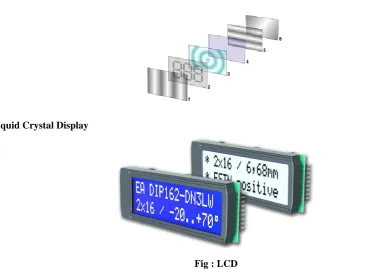
Liquid Crystal Display:
Liquid Crystal Display
Fig : LCD
Liquid crystal display is very important device in embedded system. It offers high flexibility to user as he can
display the required data on it. But due to lack of proper approach to LCD interfacing many of them fail. Many
people consider LCD interfacing a complex job but according to me LCD interfacing is very easy task, you just
need to have a logical approach. This page is to help the enthusiast who wants to interface LCD with through
understanding. Copy and Paste technique may not work when an embedded system engineer wants to apply
LCD interfacing in real world projects.
You will be knowing about the booster rockets on space shuttle. Without these booster rockets the space shuttle
would not launch in geosynchronous orbit. Similarly to understand LCD interfacing you need to have booster
rockets attached! To get it done right you must have general idea how to approach any given LCD.This page
82 | P a g e
First thing to begin with is to know what LCD driver/controller is used in LCD.Yes, your LCD is dumb it doesnot know to talk with your microcontroller. LCD driver is a link between the microcontroller and LCD. You can
refer the datasheet of LCD to know the LCD driver for e.g. JHD 162A is name of LCD having driver
HD44780U.You have to interface the LCD according to the driver specification. To understand the algorithm of
LCD interfacing user must have datasheet of both LCD and LCD driver. Many people ignore the datasheets and
end up in troubles. If you want to interface LCD successfully you must have datasheets.
In LCD initialization you have to send command bytes to LCD. Here you set the interface mode, display mode,
address counter increment direction, set contrast of LCD, horizontal or vertical addressing mode, color format.
This sequence is given in respective LCD driver datasheet. Studying the function set of LCD lets you know the
definition of command bytes. It varies from one LCD to another. If you are able to initialize the LCD properly
90% of your job is done.
Next step after initialization is to send data bytes to required display data RAM memory location. Firstly set the
address location using address set command byte and than send data bytes using the DDRAM write command.
To address specific location in display data RAM one must have the knowledge of how the address counter is
incremented.
IV. RESULT
V. CONCLUSION
Fingerprint authentication system applied to the social endowment insurance system, has basically met the
needs of the first set, can be achieved, or for retirees who retired fingerprint registration formalities, and then
retired regular or irregular acquisition of the original fingerprint to compare the fingerprint to verify the retirees
to the survival of the state's purposes. Fingerprint Identification System fingerprint Authentication state and
status of real-time feedback to the i he real alternative to bus ness system. The pensions system in the traditional
manual identification of the identity of the insured’s work, improves efficiency, effectively prevent the
83 | P a g e
REFERENCES
1. ZigBee overview. http: //www.ZigBee.org/documents/ZigBee.
2. http://www.mikroe.com/chapters/view/65/
3. http://www.pantechsolutions.net/microcontroller-boards/user-manual-arm7-lpc2148-development-kit
4. Cazan R C, Chirila L V. “Remote terminal unit’s Intelligence Evolution. Proceedings of IEEE on
Automation”, Quality and Testing, Robotics, 2008, pp. 300-303.
5. Wilson A J. “The use of GPRS technology for electricity network telecontrol”. Computing & Control