University of Pennsylvania
ScholarlyCommons
Publicly Accessible Penn Dissertations
Summer 8-13-2010
Energy Efficient Load Latency Tolerance:
Single-Thread Performance for the Multi-Core Era
Andrew D. Hilton
University of Pennsylvania, [email protected]
Follow this and additional works at:http://repository.upenn.edu/edissertations
Part of theOther Computer Sciences Commons
This paper is posted at ScholarlyCommons.http://repository.upenn.edu/edissertations/188 Recommended Citation
Hilton, Andrew D., "Energy Efficient Load Latency Tolerance: Single-Thread Performance for the Multi-Core Era" (2010).Publicly Accessible Penn Dissertations. 188.
Energy Efficient Load Latency Tolerance: Single-Thread Performance for
the Multi-Core Era
Abstract
Around 2003, newly activated power constraints caused single-thread performance growth to slow
dramatically. The multi-core era was born with an emphasis on explicitly parallel software. Continuing to grow single-thread performance is still important in the multi-core context, but it must be done in an energy efficient way.
One significant impediment to performance growth in both out-of-order and in-order processors is the long latency of last-level cache misses. Prior work introduced the idea of load latency tolerance---the ability to dynamically remove miss-dependent instructions from critical execution structures, continue execution under the miss, and re-execute miss-dependent instructions after the miss returns. However, previously proposed designs were unable to improve performance in an energy-efficient way---they introduced too many new large, complex structures and re-executed too many instructions.
This dissertation describes a new load latency tolerant design that is both energy-efficient, and applicable to both in-order and out-of-order cores. Key novel features include formulation of slice re-execution as an alternative use of multi-threading support, efficient schemes for register and memory state management, and new pruning mechanisms for drastically reducing load latency tolerance's dynamic execution overheads.
Area analysis shows that energy-efficient load latency tolerance increases the footprint of an out-of-order core by a few percent, while cycle-level simulation shows that it significantly improves the performance of
memory-bound programs. Energy-efficient load latency tolerance is more energy-efficient than---and synergistic with---existing performance technique like dynamic voltage and frequency scaling (DVFS).
Degree Type Dissertation
Degree Name
Doctor of Philosophy (PhD)
Graduate Group
Computer and Information Science
First Advisor Amir Roth
Keywords
BOLT, iCFP, Computer Architecture, Latency Tolerance, Speculative Retirement
ENERGY EFFICIENT LOAD LATENCY TOLERANCE:
SINGLE-THREAD PERFORMANCE FOR THE
MULTI-CORE ERA
Andrew D. Hilton
A DISSERTATION in
Computer and Information Science
Presented to the Faculties of the University of Pennsylvania in
Partial Fulfillment of the Requirements for the Degree of Doctor of Philosophy
2010
Amir Roth, Associate Professor of Computer and Information Science Supervisor of Dissertation
Jianbo Shi, Associate Professor of Computer and Information Science Graduate Group Chairperson
Dissertation Committee
Energy Efficient Load Latency Tolerance: Single-Thread
Performance for the Multi-Core Era
COPYRIGHT
2010
Acknowledgements
Graduate school has been a long journey with many ups and downs, successes and frus-trations, joys and sorrows. There are many people who I would like to thank for their help along the way.
First, I would like to thank my advisor, Amir Roth. If not for my enjoyment of your class, I would probably have never become an architect. Your help along the way has been invaluable—advice, refinements to ideas, and encouragement.
I would like to thank my committee—Milo Martin, Jose Martinez, Andre DeHon, and Rahul Mangharam—for their useful advice and suggestions along the way.
My academic siblings—Vlad Petric, Anne Bracy, and Tingting Sha—have provided help and encouragement, and have been with me through many all-nighters. I would also like to thank the other members of my research group, past and present—Marc Corliss, Colin Blundell, Arun Raghavan, Santosh Nagarakatte, Neeraj Eswaran, and Vivek Rane.
I have had many outstanding friends here, who provided moral support and encour-agement, as well as fun. Jeff Vaughan and Nick Taylor were the best house-mates one could ask for. I’d also like to thank Karl Mazurak, Kuzman Ganchev, Brian Aydemir, Emily Pitler, and Jenn Wortman Vaughan for their friendship and support. I’d like to thank Maestro Mark Masters and everyone at the Fencing Academy of Philadelphia for all the enjoyment I had fencing during my time in graduate school.
ABSTRACT
ENERGY EFFICIENT LOAD LATENCY TOLERANCE: SINGLE-THREAD PERFORMANCE FOR THE MULTI-CORE ERA
Andrew D. Hilton Amir Roth
Around 2003, newly activated power constraints caused single-thread performance growth to slow dramatically. The multi-core era was born with an emphasis on explicitly parallel software. Continuing to grow single-thread performance is still important in the multi-core context, but it must be done in an energy efficient way.
One significant impediment to performance growth in both out-of-order and in-order processors is the long latency of last-level cache misses. Prior work introduced the idea ofload latency tolerance—the ability to dynamically remove miss-dependent instructions from critical execution structures, continue execution under the miss, and re-execute miss-dependent instructions after the miss returns. However, previously proposed designs were unable to improve performance in an energy-efficient way—they introduced too many new large, complex structures and re-executed too many instructions.
This dissertation describes a new load latency tolerant design that is both energy-efficient, and applicable to both order and out-of-order cores. Key novel features in-clude formulation of slice re-execution as an alternative use of multi-threading support, efficient schemes for register and memory state management, and new pruning mecha-nisms for drastically reducing load latency tolerance’s dynamic execution overheads.
Contents
Acknowledgements iii
1 Introduction 1
1.1 DVFS: Accelerating Computation-Bound Programs . . . 2
1.2 Load Latency Tolerance: Accelerating Memory-bound Programs . . . 4
1.3 Energy Efficient Load Latency Tolerance: BOLT and iCFP . . . 5
1.4 Contributions . . . 9
1.5 Previously Published Work . . . 10
1.6 Document Organization . . . 11
2 Background 12 2.1 Non-scalability of the Out-of-order Window . . . 14
2.1.1 Issue Queue . . . 14
2.1.2 Physical Register File . . . 18
2.1.3 Store Queue . . . 21
2.1.4 Load Queue . . . 23
2.1.5 Load Latency Tolerance: Virtually Scaling the Window . . . 25
2.2 Runahead Execution . . . 27
2.2.1 Load and Store Queues . . . 28
2.3 Checkpointed Early Load Retirement and
Checkpoint Assisted Value Prediction . . . 29
2.3.1 Load and Store Queues . . . 30
2.4 Waiting Instruction Buffer . . . 30
2.5 Continual Flow Pipelines . . . 31
2.5.1 Register management: Checkpoint Processing and Recovery . . . 32
2.5.2 Slice Management and Processing . . . 33
2.5.3 Load and store management . . . 34
2.6 KILO- and Decoupled KILO-Instruction Processors . . . 36
2.6.1 Decoupled KILO-Instruction Processor . . . 36
2.6.2 Scalability of Load Latency Tolerant Designs . . . 37
2.7 Scalable Load and Store Queues . . . 39
2.7.1 Store Vulnerability Window (SVW) . . . 39
2.7.2 Store Queue Index Prediction (SQIP) . . . 40
2.7.3 SVW/SQIP Example . . . 40
2.7.4 Multiprocessor Issues . . . 42
2.7.5 Scalability . . . 43
3 BOLT Microarchitecture 46 3.1 BOLT Overview . . . 47
3.2 Register Management . . . 52
3.2.1 ROB-style Register Management as Reference Counting . . . 53
3.2.2 Combining ROB-style and CPR-style Register Management . . . 55
3.2.3 Tracking Live-Out Destination Registers of Deferred Instructions 55 3.3 Store-to-load Forwarding . . . 58
3.3.1 Chained Store Buffer Mechanics . . . 60
3.3.2 Implementation Issues . . . 63
3.4 Load Verification . . . 66
3.4.2 Verification Relative to Stores from Other Threads . . . 69
3.5 Instruction Granularity Retirement . . . 72
3.5.1 SDR (Silent Deterministic Replay) and DSC (Decoupled Store Completion) . . . 73
4 Dynamic Efficiency 75 4.1 Miss Re-execution Pruning . . . 75
4.1.1 Implementation: Antidotes . . . 76
4.1.2 Store-to-load Dependences . . . 78
4.1.3 Restarting A Re-execution Pass: Optimizing Loads that Return Out of Order . . . 79
4.1.4 Need For More Sophisticated Pruning . . . 79
4.2 Join Re-execution Pruning: Optimizing Parallel Load Misses . . . 80
4.2.1 Implementation: Refining Antidote Propagation . . . 82
4.3 Pointer-chasing Deferral Pruning: Optimizing Dependent Load Misses . . 84
4.3.1 Implementation: Extended Antidote Bit-vectors . . . 86
4.3.2 Design Choices . . . 88
5 Performance Analysis 90 5.1 BOLT Configuration: Load Latency Tolerance for L2 and L3 Misses . . . 98
5.2 BOLT vs. DVFS . . . 100
5.3 BOLT vs. Runahead . . . 102
5.4 BOLT vs. CFP . . . 105
5.4.1 Effect Isolation: Register Substrate . . . 107
5.4.2 Effect Isolation: Load and Store Queue Designs . . . 109
5.4.3 Effect Isolation: Pruning Mechanisms . . . 111
5.5 Summary Comparison . . . 113
5.5.1 Behavior on Non-Memory Bound Benchmarks . . . 114
5.6 Why Not a Transactional Data Cache? . . . 117
5.6.1 Design . . . 118
5.6.2 Evaluation . . . 119
5.7 Sensitivity Analysis . . . 124
5.7.1 Load and Store Queue Capacity . . . 125
5.7.2 CSB Root Table Capacity . . . 126
5.7.3 Slice Buffer Capacity . . . 128
5.7.4 Issue Queue Capacity . . . 129
5.7.5 Issue Queue and Physical Register File Capacity . . . 130
5.7.6 Baseline Micro-architecture Sensitivity . . . 132
6 iCFP: Load Latency Tolerance for In-order Processors 134 6.1 iCFP: In-order Continual Flow Pipeline . . . 135
6.1.1 Register Management . . . 135
6.1.2 Store-Load Forwarding . . . 138
6.1.3 Load Verification . . . 138
6.2 Other In-order Load Latency Tolerance Designs . . . 139
6.2.1 Runahead Execution . . . 139
6.2.2 “Flea-flicker” Multipass Pipelining . . . 140
6.2.3 Simple Latency Tolerant Processor . . . 141
6.2.4 Sun’s Rock . . . 143
6.2.5 Qualitative Comparison Summary . . . 144
7 Conclusions 147 7.1 Future Work . . . 148
Appendices 151
List of Tables
3.1 CSB Run-bit Rules . . . 66
4.1 Antidote Bit-vectors: Miss Pruning . . . 77
4.2 Antidote Bit-vectors: Join Pruning . . . 82
5.1 Simulated processor configurations . . . 91
5.2 Benchmark characterization . . . 94
5.3 Area Overheads (mm2) . . . . 98
5.4 Comparison and contrast of out-of-order load latency tolerant designs. . . 116
5.5 Area and energy costs for age and poison tracking in BOLT+TD$ . . . . 120
5.6 Area Overheads (mm2) . . . 121
List of Figures
1.1 Clock frequency performance and ED2 . . . . 3
1.2 Example Cache Hierarchy . . . 4
1.3 Performance and ED2comparison: CFP, BOLT . . . . 8
2.1 Performance Impact of Load Latency . . . 13
2.2 Energy scaling of the issue queue. The dashed line indicates designs where 1-cycle wakeup/select requires increasing voltage or decreasing clock frequency. . . 15
2.3 Performance scaling of the issue queue. . . 16
2.4 Slowdowns from 2-cycle wakeup/select . . . 17
2.5 Energy and latency scaling of the register file. Numeric labels indicate access time in 3.2 GHz clock cycles. The x-axis is labeled with both the register file size, and the corresponding Reorder Buffer (ROB) size in parenthesis. . . 19
2.6 Performance impact of register file. . . 20
2.7 Energy scaling of the store queue. . . 22
2.8 Performance impact of store queue. . . 23
2.9 Energy scaling of the load queue. . . 24
2.10 Performance impact of store queue. . . 24
2.11 Execution Example: Runahead Execution . . . 27
2.12 Execution Example: WIB . . . 31
2.14 Scalability of a slice buffer . . . 38
2.15 Example: SVW and SQIP . . . 41
2.16 Energy scaling of the load queue with SVW. . . 43
2.17 Energy scaling of the store queue with SQIP. . . 44
3.1 Structural diagram of BOLT. BOLT-specific structures are shaded grey. . . 47
3.2 BOLT Pipeline . . . 48
3.3 Structural diagram of BOLT with register management related structures highlighted. . . 52
3.4 ROB-style Register Management as Reference Counting . . . 53
3.5 Slice Live-out Destination Registers . . . 56
3.6 Structural diagram of BOLT with store management related structures highlighted. . . 59
3.7 Chained Store Buffer . . . 61
3.8 CSB Search . . . 62
3.9 Structural diagram of BOLT with load verification related structures high-lighted. . . 67
3.10 Circular Dependence in a Checkpoint . . . 72
3.11 DSC/SDR . . . 74
4.1 Structural diagram of BOLT with the antidote bit-vector highlighted. . . . 77
4.2 Code Example: Parallel Loads . . . 80
4.3 Execution Example: Parallel Loads . . . 81
4.4 Antidote Propagation and Pruning . . . 83
4.5 Code Example: Serial Loads . . . 84
4.6 Execution Example: Pointer Chasing . . . 85
4.7 Code Example: Benign Indirection . . . 86
5.1 Applying BOLT to L3 misses only or to L2 and L3 misses . . . 99
5.3 Performance of BOLT and Baseline at various clock frequencies . . . 102
5.4 Applying Runahead to L3 misses only or to L2 and L3 misses with and without pruning. . . 103
5.5 Applying CFP’s load latency tolerance to L3 misses only or to L2 and L3 misses . . . 106
5.6 Comparison of CFP and BOLT register substrate . . . 108
5.7 BOLT with three different load and store queue designs. . . 110
5.8 Impact of BOLT’s pruning algorithms . . . 111
5.9 Runahead, CFP, and BOLT . . . 113
5.10 Performance on Non-memory-Bound Benchmarks . . . 114
5.11 BOLT+TD$ vs. BOLT . . . 122
5.12 BOLT+TD$ squashes per 10,000µops . . . 123
5.13 Sensitivity to load and store queue sizes. . . 125
5.14 Sensitivity to CSB’s root table size. . . 126
5.15 Load hop histograms . . . 127
5.16 Sensitivity to slice buffer size . . . 128
5.17 Sensitivity to issue queue size . . . 129
5.18 Sensitivity to ROB/IQ size . . . 131
6.1 BOLT vs iCFP . . . 136
A.1 Performance Impact of SVW-MT . . . 152
A.2 Impact of number of bits used for SVW-MT filtering . . . 154
B.1 Comparison of dynamic energy model parameterδ. . . 157
B.2 Comparison of static energy model parameterσ. . . 157
Chapter 1
Introduction
Historically, efforts to extract single-thread performance at almost any cost have been a significant theme in computer architecture. Starting around 2005, this trend changed as energy became a primary concern in a wide range of domains—from embedded devices in which battery life is critical to large server rooms where power supply and cooling costs dominate budgets.
The need for more energy-efficient performance has led to the proliferation of multi-core designs. Multiple independent multi-cores can deliver high performance if programs are written to take advantage of them—explicitly multi-threaded, so that threads can run on different cores. The energy efficiency of multi-core designs comes from avoiding the quadratic costs associated with many aspects of single-thread performance. Four tures of size N consume less energy than one structure of size 4N. Similarly, four struc-tures with one port each consume less energy than one structure with four ports, and four cores operating at 1GHz consume less energy than one core operating at 4GHz.
Future multi-cores are likely to be heterogeneous and will include a small number of large high-performance cores (i.e., superscalar, out-of-order cores similar to Intel’s Core i7) and a large number of small simple cores (i.e., scalar, in-order similar to Intel’s Atom). The simple cores will execute parallel regions of code, while the large cores will execute serial regions. One aspect of exploiting multi-cores is parallelizing important applications. However, an equally important aspect is single-thread performance of both the small and large cores. The large cores will have to deliver high performance to prevent the serial por-tions of the workload from dominating performance [29]—this is Amdahl’s Law. While the small cores will exploit parallelism where it exists, their individual performance will be important because parallelism is not perfectly elastic—many applications will not scale to arbitrarily large numbers of threads. Because energy considerations will limit the num-ber of cores which may be active at any given time, the performance techniques used in both the high-performance and simple cores must be energy efficient.
1.1 DVFS: Accelerating Computation-Bound Programs
0 5 10 15 20 25
% Speedup
0 25 50
% ED2 Change
milcmcfsoplexlbmlibqgemsspnxcactuszeusmpsjenggcc wrflsl3ddealIIcalculixastargamessbzip2gobmkxalanch264omnetnamdtontopovrayhmmerAVG
Figure 1.1: Top: Performance impact of using DVFS to increase clock frequency from 3.2 GHz to 4.0 GHz on a simulated design similar to Core i7. Bottom: Energy efficiency as measured by percent change in Energy×Delay2.
and clock frequency of that core are increased. DVFS increases the energy consump-tion of the core quadratically, so it cannot be applied to all cores at once, and it most likely requires other cores to be powered down in order to meet the power budget. This quadratic increase in energy consumption corresponds to a linear increase in performance in the ideal case, when a program experiences no cache misses and its performance is constrained by in-core computation. It corresponds to almost no increase in the worst case, when a program misses the cache frequently and its performance is constrained by latencies outside the core.
L3 Cache (~40 cycles) Main Memory (~250 cycles)
L2$ (10) L1$
Core i7
L2$ (10) L1$
Atom
L1$
Atom
L2$ (10) L1$
Atom
L1$
Atom
L2$ (10) L1$
Atom
L1$
Atom
Figure 1.2: An example cache hierarchy for a hypothetical future heterogenous multi-core chip.
the benchmarks on the right side of the graph obtain ideal speedups, other benchmarks do not. In fact, the left-most benchmarks (mcf, milc, soplex, etc.) on the graph obtain little speedup. Correspondingly, these benchmarks have significant increases in ED2—almost 50%—indicating that their performance gains are highly energyinefficient. The problem with these programs is that they are memory-bound—their performance is dominated by misses to memory or to the last level cache, which are not in the core’s clock domain and are not affected by DVFS.
1.2 Load Latency Tolerance:
Accelerating Memory-bound Programs
for in-order—quickly fill and executions halts. Latencies that are long enough to pose significant performance issues can be incurred not only by accesses which go all the way to main memory, but also by sufficiently large numbers of accesses which are serviced by the L3 cache. For an in-order core, a program may be memory-bound due to a sufficiently large number of L1 misses, even if they hit in the L2.
Increasing the core’s clock frequency does little to help memory-bound programs. Only the first two levels of cache (shown in light grey) operate on the same clock as the core. The L3 cache and main memory, are in different clock domains. Accesses handled at these levels take the same amount of time no matter what the core’s clock frequency is. Increasing the clock frequency however, makes these accesses take relatively more clock cycles, meaning that the core consumes more energy while waiting for the data.
Previous work [44, 58, 60, 76] introduced the technique of load latency tolerance— long-latency misses and their dependents temporarily release their resources, wait on the side, then re-execute after the miss returns. Load latency tolerant processors improve the performance of memory-bound programs by allowing the pipeline to continue to execute younger instructions while waiting for the long-latency miss to return. However, previous latency-tolerant processor designs are not energy-efficient. They used too many additional structures and deferred and re-executed too many miss-dependent instructions to justify their performance gains.
1.3 Energy Efficient Load Latency Tolerance:
BOLT and iCFP
introduced by re-executing instructions. This dissertation describes BOLT (Better Out-of-order Latency Tolerance) [35] and iCFP (In-order Continual Flow Pipeline) [31] re-spectively out-of-order and in-order load latency tolerant designs which achieve energy efficiency. BOLT and iCFP implement the re-execution of miss-dependent instructions as an alternative use of multi-threading hardware, maximizing re-use of existing struc-tures. They avoid associative structures for load and store management, favoring simple, low-overhead indexed structures. Additionally, they employ simple pruning techniques to minimize the re-execution overheads introduced by load latency tolerance. This disserta-tion focuses primarily on BOLT. It includes a detailed descripdisserta-tion of all mechanisms and a comparative, simulation-driven performance evaluation. In the interest of completeness, it also describes iCFP and qualitatively compares it to other in-order load latency tolerant designs. However, it does not include a simulation-driven performance/energy evaluation of iCFP1.
The novel mechanisms presented in this dissertation include:
• Out-of-order register management for load latency tolerance. This dissertation
describes an efficient implementation of a new hybrid physical register manage-ment algorithm for out-of-order load latency tolerant processors. This new algo-rithm combines the benefits of conventional register management for the youngest in-flight instructions with the benefits of aggressive register reclamation for the old-est miss-dependent instructions. This register management scheme also allows re-renaming of miss-dependent instructions to be framed as an alternative use of exist-ing multi-threadexist-ing hardware.
• In-order register management for load latency tolerance. This dissertation
de-scribes efficient register management for an in-order load latency tolerant proces-sor. Like the out-of-order design, the in-order design frames re-execution of miss-dependent instructions as an alternative use for existing multi-threading support.
1Simulated performance results for iCFP are available in previously published work [31], however, that
• Pruning mechanisms for load latency tolerance.This dissertation describes prun-ing mechanisms which reduce the number of instructions requirprun-ing re-execution. These mechanisms address two different forms of inefficiency—avoiding unneces-sary re-execution and avoiding applying load latency tolerance to “pointer chasing” code, where it is ineffective.
• Chained Store Buffer. This dissertation describes a chained store buffer—a novel scalable, searchable store buffer design. Scalable search is obtained by overlaying an address-indexed hash-table on top of an indexed store buffer, allowing loads to search using iterative indexed access.
• SVW-MT. This dissertation describes SVW-MT—the inter-thread verification
as-pects of SVW—and two optimizations needed to make it work efficiently.
• Decoupled Store Completion/Silent Deterministic Replay. This dissertation
describes Silent Deterministic Replay (SDR), a technique which permits non-speculative retirement of instructions in between checkpoints in a non-speculative retirement setting. SDR enables Decoupled Store Completion (DSC), the ability to non-speculatively complete stores to the data cache before the checkpoint they reside in is completed.
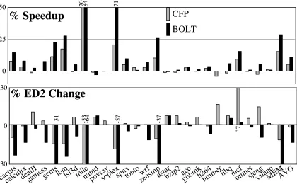
Figure 1.3 highlights the results presented in this dissertation. It compares Continual Flow Pipelines [76], the prior state-of-the-art out-of-order load latency tolerant design, to BOLT in terms of performance (top, higher is better) and energy efficiency (bottom, lower is better). A more detailed comparison of the two micro-architectures is presented in Section 5.4. These results show three significant advantages for BOLT:
• Performance. BOLT out-performs CFP by a significant amount. The difference
0 25 50
CFP
BOLT
70 84 71% Speedup
-30 0 30
37
-53
-31 -64 -57 -37
% ED2 Change
cactuscalculixdealIIgamessgemslbmlsl3dmilcnamdpovraysoplexspnxtontozeusmpwrf astarbzip2gccgobmkh264hmmerlibqmcfomnetsjengxalancMEMAVG Figure 1.3: Top: The performance improvements of Continual Flow Pipelining (prior state-of-the-art load latency tolerant design), and BOLT. Bottom: The corresponding percent change in ED2.
• Energy efficiency. BOLT has significantly better energy efficiency (lower ED2) than CFP. While CFP averages only 1% ED2 improvement overall and 11% on the memory-bound subset of SPEC, BOLT averages 13% overall and 30% on the memory-bound programs.
• Performance and energy efficiency robustness.BOLT more closely adheres to the
1.4 Contributions
The main contributions of this dissertation are:
• Similarities of in-order and out-of-order load latency tolerance. This
disserta-tion shows that both in-order and out-of-order processors can tolerate load latency using almost identical mechanisms.
• Framing re-execution as multi-threading. This dissertation shows that the
in-structions re-executed by load latency tolerant designs behave similarly to a thread. BOLT and iCFP re-use existing multi-threading support for this re-execution.
• Hybrid register management in out-of-order processors.This dissertation shows
how different register management schemes may be hybridized in an out-of-order processor using reference counting. In BOLT, this hybridization is used to attach a register-efficient post-processing step to a conventional out-of-order processor.
• Efficient, scalable load/store queue design. This dissertation shows how SQIP,
CSB, DSC/SDR, SVW, and SVW-MT can be combined into an efficient, scalable load/store queue design which is well-suited to load latency tolerance in an out-of-order processor. An in-out-of-order latency processor does not need SQIP and SVW, but can use the other mechanisms.
• Deferral and re-execution pruning mechnaisms. This dissertation shows that
re-execution overheads can be a significant energy in-efficiency in a load latency tol-erant design, and proposes mechanisms to address the inefficiency while still main-taining performance.
1.5 Previously Published Work
Aspects of this dissertation have been published already. These publications include:
• iCFP: Tolerating All-Level Cache Misses in In-Order Processors. This 2009
publication appeared in the 15th International Symposium on High Performance Computer Architecture [31]. It describes the in-order register state management in iCFP, as well as the chained store buffer. iCFP also appeared in MICRO’s Top-Picks [32]. That manuscript also included a qualitative comparison of iCFP and Sun’s Rock processor.
• DSC/SDR: Enabling Scalable Data Memory for CPR/CFP Processors. This
2009 publication appeared in the 36th International Symposium on Computer Ar-chitecture [34]. It describes Decoupled Store Completion and Silent Deterministic Replay.
• BOLT: Energy-Efficient Out-of-Order Latency-Tolerant Execution. This 2010
publication appeared in the 16th International Symposium on High Performance Computer Architecture [35]. It describes BOLT— the out-of-order load latency tolerance design—including its register management and pruning mechanisms.
This dissertation differs from the previously published work in the following ways:
• BOLT is evaluated more thoroughly.
• SVW-MT is explained in detail, including optimizations which make it work effi-ciently.
• The “pointer chasing” pruning mechanism presented in this dissertation (in
1.6 Document Organization
Chapter 2
Background
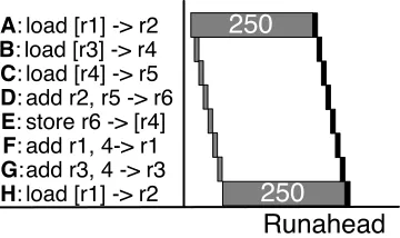
Long latency loads pose a significant performance problem, as the processor must stall for many cycles while waiting for data. This problem can be mitigated by a processor’s ability to execute independent instructions while waiting for a long latency miss to return. Gains can come from one of two types of parallelism. Memory-level parallelism (MLP) oc-curs when the processor overlaps the memory latency of two or more independent loads. Instruction-level parallelism (ILP) occurs when the processor executes independent in-structions under the miss, preserves that work, and does not revisit those inin-structions after the miss returns. Both forms of parallelism are limited by the processor’s ability to re-order instructions and find independent operations. Alternatively, the processor may decrease its voltage and clock frequency while a long latency miss is pending to save energy [45].
A: load [r1] -> r2 B: load [r3] -> r4 C: load [r4] -> r5 D: add r2, r5 -> r6 E: store r6 -> [r4] F: add r1, 4-> r1 G:add r3, 4 -> r3
H: load [r1] -> r2 250
250
250
250
250
250
In-order Out-of-order
8-insn window
Out-of-order 6-insn window
Figure 2.1: Execution behavior over time. Loads A and H miss the caches. Left: An in-order processor serializes all instructions. The misses dominate performance. Middle: An out-of-order processor can execute independent operations while waiting for A’s miss to return. It may be able to overlap A’s miss with H’s, exposing MLP. Right: If the out-of-order processor’s window is too small, it may not be able to overlap A and H, resulting in performance closer to the in-order case.
miss latencies dominate performance, accounting for 99% of execution time.
In many real processors, sequential accesses such as those in Figure 2.1 are often detected and prefetched—a dedicated hardware structure monitors cache accesses, detects simple patterns, and initiates misses before any load attempts to read the data [17, 18, 39, 40, 70, 71]. Prefetching improves performance, but is limited by the types of patterns it can discern. Many of the examples in this dissertation ignore prefetching to facilitate simple and clear examples. However, the simulated results in Chapter 5 include stream prefetching all configurations.
The middle of Figure 2.1 shows the performance gains that an out-of-order processor can achieve in this same situation. Here, the processor can execute independent instruc-tions B, C, F, G, and H while it waits for A’s miss to return. The most significant per-formance gain here comes from MLP—the out-of-order processor overlaps H’s miss with A’s, meaning their latencies no longer add. The processor also obtains some performance gains from ILP—the execution of B,C, F, and G—however, in this example, those gains are a small component of the overall performance improvement.
window determines how much ILP and MLP an out-of-order processor can extract under a miss. The out-of-order processor in the middle of Figure 2.1 has a window of eight instructions, meaning it can examine all instructions from A to H to find independent instructions. By contrast, if the out-of-order window were only six instructions, as pictured on the right side of Figure 2.1, then the processor could not execute G until A finished and exited the window. The important consequence of this smaller window is that H cannot execute until after A exits the window, again serializing the misses and causing their latencies to add.
2.1 Non-scalability of the Out-of-order Window
While a large out-of-order window is desirable for performance, it is neither practical nor energy efficient. The out-of-order window is restricted by four non-scalable structures: the issue queue, the physical register file, the load queue, and the store queue. In modern, conventional out-of-order processors, these structures are sized to tolerate moderate laten-cies of about 20–30 cycles. Latenlaten-cies of this magnitude correspond to last-level cache hits, serially dependent loads hitting the L2 cache, or the longest floating point operations. To tolerate the long latency of last-level cache misses—250 cycles—the capacities of these structures would have to increase by 4–10×. Such increases would drastically increase the access latency and energy consumption of these structures.
2.1.1 Issue Queue
0 25 50 75 100
1 cycle, V. up/F. down 1 cycle wakeup/select 2 cycle wakeup/select
V: +2%
V: +14%
V: +29%
V: +62%
F: -1%
F: -8%
F: -17%
F: -35%
16 3648 64 128 256 512
Wakeup Energy (pJ)
Issue Queue Capacity
Figure 2.2: Energy scaling of the issue queue. The dashed line indicates designs where 1-cycle wakeup/select requires increasing voltage or decreasing clock frequency.
un-executed instructions. The issue queue in the Intel Core i7 processor has 36 entries, limiting the out-of-order window to 36 un-executed instructions.
Physical scalability. One difficulty with scaling the issue queue arises from the fact that its latency is critical. Scheduling that takes multiple clock cycles, prevents dependent instructions from executing in consecutive cycles. Essentially, the minimum execution la-tency in the processor becomes that of the scheduler’swakeup/selectloop. The complexity (and therefore latency) of both wakeup and select increases as the size of the issue queue increases [56].
0 25 50 75
Memory Bound (1 cycle) Memory Bound (2 cycle)
SPEC 2006 (2 cycle) SPEC 2006 (1 cycle)
36 64 128 256 512 1024
% Speedup
Issue Queue Capacity
Figure 2.3: Performance scaling of the issue queue for both 1- and 2-cycle wakeup/select. All other window structures are infinite.
for the select logic. The data in the graph uses this estimation—20.5 ps—for all points and does not model the longer select latencies of larger issue queues.
The line marked by dark circles in Figure 2.2 plots the energy requirements for differ-ent issue queues sizes when the wakeup/select loop is constrained to a single cycle. For issue queue sizes of 64-entries and larger, CACTI is unable to produce any configuration which permits single-cycle wakeup/select at the baseline clock frequency and voltage. Is-sue queue designs of these sizes with single-cycle wakeup/select require either increasing voltage or decreasing clock frequency (or some of both). These designs are indicated with slightly lighter circles and a dashed line. Each point has the voltage increase/frequency decrease noted above/below it. The energy values plotted do not account for the voltage changei.e., they are the energy required if frequency were changed. The line marked with light triangles shows the energy consumption when wakeup/select is relaxed to two cycles.
Performance impact. Figure 2.3 shows the geometric mean speedup over the
-20 -10 0
10 36 (1-cycle) 36 (2-cycle) 512 (1-cycle) 512 (2-cycle)
% Speedup
povray astar bzip2 gcc gobmk hmmer omnet xalanc
Figure 2.4: Slowdowns suffered by individual programs from 2-cycle wakeup/select.
the other structures. The clock frequency is un-modified in all experiments.
Maximizing IPC throughput on the memory-bound programs requires a 512-entry is-sue queue. Such a design requires a 6–7×increase in the per-search energy of the issue
queue as well as either 2-cycle wakeup select, a 35% frequency decrease, or a 62% volt-age increase. Neither drastically increasing voltvolt-age nor decreasing frequency are attractive options. The 2-cycle wakeup/select design is also not attractive [10]. Experiments show that programs sufferaverageperformance losses of about 7%. However, the designs with 2-cycle wakeup/select suffer slowdowns compared to the baseline for individual bench-marks.
Figure 2.4 shows the impact of 2-cycle wakeup select on individual benchmarks. The graph shows four bars—36-entry/1-cycle, 36-entry/2-cycle, entry/1-cycle, and 512-entry/2-cycle. The benchmarks selected for this graph are those which suffer a slowdown of greater than 2% in the 512-entry/2-cycle configuration. These programs suffer from the latency added to operations which are normally single-cycle. Some of these programs (e.g., povray, gcc, andbzip2) mitigate this cost slightly by having large window, but the longer latency operations are the dominant effect here.
linked lists—the readers of a given register are chained in a list that starts at that register— and implements wakeup by following list pointers. Forwardflow scales the issue queue, but may impact performance for long dependence listsi.e., register values with high fan-out.
Other techniques examine modifications to the traditional wakeup/select-based design. One approach exploits the fact that most instructions entering the window need to only wait for one input to become available. Putting such instructions into a CAM which only matches one physical register tag allows for lower latency and energy [23]. Other approaches create a large issue queue from multiple smaller structures [56, 63].
Other techniques attack the latency problem of wakeup/select fitting in one cycle, while allowing dependent instructions to issue in consecutive cycles. One approach speculatively wakes up grandchildren (i.e., a dependent instruction’s dependent instruc-tions) [77]. This allows wakeup and select to take two cycles, but requires issue queue entries to hold more tags (i.e. the parents’ inputs) or to speculate one which inputs will arrive last.
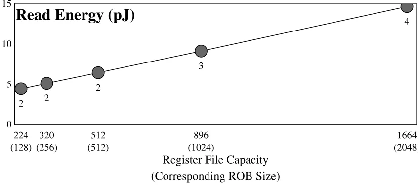
2.1.2 Physical Register File
0 5 10 15
2 2
2
3
4
224 320 512 896 1664
(128) (256) (512) (1024) (2048)
Read Energy (pJ)
Register File Capacity (Corresponding ROB Size)
Figure 2.5: Energy and latency scaling of the register file. Numeric labels indicate access time in 3.2 GHz clock cycles. The x-axis is labeled with both the register file size, and the corresponding Reorder Buffer (ROB) size in parenthesis.
The consequence of this conventional register management scheme is that the total num-ber of register writing instructions between rename and retirement is limited by the size of the physical register file. The physical register file is both latency-critical and high-bandwidth. The latency of the physical register file impacts the number of pipeline stages between issue and execution. Increasing the number of pipeline stages here increases the bypass complexity, scheduler speculation depth and complexity, and the branch mis-prediction penalty. The register file must also support 2N reads and N writes on an N-wide processor. On a 4-wide out-of-order machine, this means the register file requires 12 ports. This bandwidth requirement may be reduced slightly under the assumption that some in-structions will receive inputs from the bypass network rather than the register file and that some instructions will not produce register output values. The combination of these two factors limits the register file to a modest number of entries—in Intel’s Core i7, enough to support architected state plus about 128 in-flight instructions.
0 25 50 75
SPEC 2006 Memory Bound
224 320 512 896 1664
(128) (256) (512) (1024) (2048)
% Speedup
Register File Capacity (Corresponding ROB Size)
Figure 2.6: Performance impact of register file. Other window structures are infinite. The x-axis is labeled with both the register file size, and the corresponding Reorder Buffer (ROB) size in parenthesis.
corresponding Reorder Buffer (ROB) size is listed in parenthesis. Specifically, this is the ROB size appropriate for the given register file size, assuming 128 architectural registers (64 per-thread with two threads), and that three-quarters of instructions require an output register. The register file access latency in clock cycles is listed under each point. Unlike the other window structures, CACTI does not produce significantly different numbers for the smaller register files with relaxed cycle time constraints.
Performance impact. Figure 2.6 shows the performance effects (again, geometric
mean speedup over the baseline configuration) of scaling the register file when all other window structures are ideally large. The ROB size corresponding to each register file size is listed for reference, but the ROB is treated as infinite in all simulations. These simulations also assume that the larger sizes have no impact on access latency, and model 2 cycle register reads for all configurations. An 896-entry register file (i.e., one large enough to support a 1024 instruction window) is required to achieve maximum performance. A register file this large requires 3 cycles to access instead of 2, which reduces performance by up to 3%. The access energy for a register file of this size approximately doubles compared to the baseline 224-entry register file.
register file in various ways. Some approaches, such asCheckpoint Processing and Re-covery[2],Cherry[48], andEarly Register Release[22] improve register file utilization by freeing registers sooner than in a conventional processor. Physical Register Inlining[46] releases physical registers with small values, placing the values directly in the rename map table. Other approaches, such asVirtual Physical Registers[50] allocate physical registers only when they are needed by executing instructions. Ephemeral Registers[19] combine both late allocation and early release.
Some techniques scale the effective capacity of the register file by allowing certain instructions to share registers with older instructions that produce the same value [25, 41, 61, 62, 75] or by fusing multiple instructions into larger blocks and elimianting register storage for block-interior values [11]. Most of these techniques also amplify the capacity of the issue queue.
2.1.3 Store Queue
Processors must respect data dependences via memory as well as registers. Because cache writes cannot be undone in a conventional processor, a store may not complete to the data cache until after it retires in program order. A load may read the memory location written by an older store which has not yet completed to the data cache. To avoid stalling such loads until the relevant store completes, out-of-order processors allow loads to forward values from in-flight stores. To support store-to-load forwarding, out-of-order processors use a store queue that holds the addresses and data values of in-flight stores in program order. When a load executes, it searches the store queue for an older store to the same address. If a match is found, the load uses the value forwarded from the store queue. If not match is found, the load uses the value from the data cache.
0 30 60 90 120
Associative 2 cycles Associative 3 cycles
16 32 48 64 128 256 512
Read Energy (pJ)
Store Queue Capacity
Figure 2.7: Energy scaling of the store queue.
sizes. However, the latency constraints of the store queue are somewhat more relaxed than those of the issue queue. The access latency of the store queue (the CAM plus the age logic) must fit within the data cache access latency, which is typically three or four clock cycles—in this dissertation, we assume a three-cycle data cache. The store queue in a Core i7 processor has 32 entries, limiting the window to 32 stores which have not yet completed to the data cache.
Physical scalability. Figure 2.7 shows the per-read (search) energy reported by
CACTI for the CAM portion of the associative store queue. An S-entry store queue is modeled as an S-word 12-bit CAM with a 104-bit data array, 1 indexed write port, 1 indexed read port, and 1 associative read port. Each 116-bit entry includes a 48-bit physical address—the low-order 12-bits are searched1—a 64-bit value, a 3-bit size field, and a valid bit. CACTI does not model age logic. To account for the latency of the age logic across a reasonable range of possibilities, two models are used. In the first model (shown by the top line, marked with circles), the CAM is limited to designs which fit into two clock cycles. This model assumes a full cycle for the age logic. The second model (shown by the middle line, marked with triangles) constrains the designs to three clock cycles. This model assumes zero-latency age logic. If the actual latency for the age logic is between zero and one cycle, then the actual energy curve for the store queue will fall between these two.
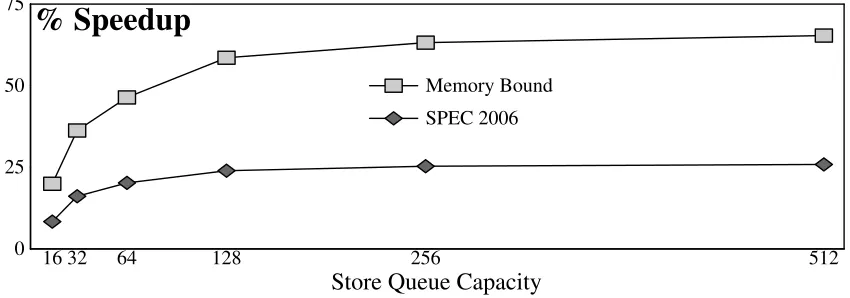
0 25 50 75
SPEC 2006 Memory Bound
16 32 64 128 256 512
% Speedup
Store Queue Capacity
Figure 2.8: Performance impact of the store queue. Other window structures are infinite.
Performance impact. Figure 2.8 shows the performance impact of varying the store
queue size when the other window structures are infinite. The top line (marked with light grey boxes) shows the geometric mean speedup for the memory-bound programs. The bottom line (marked with dark grey diamonds) shows the geometric mean speedup for all of SPEC. Memory-bound programs need at least a 128-entry store queue to fully utilize a large window. As Figure 2.7 shows, this requires a 3–5×increase in the per-read energy
of the store queue.
Other approaches. Prior research has attacked the scalability of a conventional store queue in various ways. Store Queue Index Prediction (SQIP) [74] replaces the associative store queue with an indexed store queue. SQIP is discussed in detail in Section 2.7.2. Other techniques remove the store queue entirely [75, 78]. Other techniques reduce the number of entries searched in an associative design [7, 57, 73].
2.1.4 Load Queue
0 30 60 90
Associative
16 32 48 64 128 256 512
Read Energy (pJ)
Load Queue Capacity
Figure 2.9: Energy scaling of the load queue.
0 25 50 75
SPEC 2006 Memory Bound
16 32 64 128 256 512
% Speedup
Load Queue Capacity
Figure 2.10: Performance impact of the load queue. Other window structures are infinite.
To support memory ordering violation detection, conventional out-of-order processors track the addresses of all in-flight loads in a program-order associative load queue (i.e., a CAM). Executing stores and invalidations due to stores on other processors trigger load queue searches to find any load which may have executed prematurely and read an incor-rect value. Unlike the store queue and issue queue, latency is not critical for load queue search.
Physical scalability. Figure 2.9 shows the energy scaling of an associative load queue.
AnL-entry load queue is modeled as anL-word 48-bit CAM with a 4-bit data array, one
Performance impact. Figure 2.10 shows the performance impact of scaling the load queue when all other window structures are infinitely large. A 256-entry load queue is needed to maximize performance for the memory-bound programs. A load queue this large uses approximately 5×as much energy as the baseline 48-entry load queue.
Other approaches.Prior work has attacked the scalability of the load queue primarily by re-executing loads in-order prior to commit [12, 67, 68]. One of these approaches— Store Vulnerability Window—is discussed in detail in Section 2.7.1.
2.1.5 Load Latency Tolerance: Virtually Scaling the Window
The high-level idea of load latency tolerance is to virtually scale the issue queue and physical register file. Load latency tolerance designs remove miss-dependent instructions from these key window resources to allow younger instructions to enter the pipeline and execute. When a miss returns, the instructions which depend on it are re-injected into the pipeline—re-acquiring issue queue entries and physical registers—and re-execute.
captured so that re-execution is decoupled from the main program. Memory state, how-ever, has exactly the opposite behavior of register state in each of those dimensions. First, memory state is large. Second, loads are vulnerable to stores from other threads. Third, a finite-sized snapshot cannot capture all data dependences between stores and younger loads. Finally, store-to-load dependences are only known when the address of the load and communicating store are both known, making it impossible to capture inputs in the presence of loads with unknown addresses.
In this dissertation, we define atrue load latency tolerant designas one that incorpo-rates scaling for all four window structures (the issue queue, the physical register file, the load queue, and the store queue), and retains miss-independent work completed under a miss, exploiting ILP as well as MLP. Scaling techniques for all four structures must allow them to accommodate a large enough window to avoid dispatch stalls under long latency misses, without decreasing the clock frequency or drastically increasing energy consump-tion. These techniques may include virtual scaling—removal and re-injection to achieve a larger effective size—or replacement of non-scalable associative structures with scalable indexed structures.
Several prior works make important steps towards improving performance under long-latency cache misses, but not all of them qualify as true load long-latency tolerant designs— some of these works either only address some aspects of the design, or only obtain part of the benefits of load latency tolerance. Even among those designs that do qualify as true load latency tolerance, some provide the ability to tolerate dependent long latency misses—miss-dependent loads which are themselves long latency misses—while others do not.
A: load [r1] -> r2 B: load [r3] -> r4 C: load [r4] -> r5 D: add r2, r5 -> r6 E: store r6 -> [r4] F: add r1, 4-> r1 G:add r3, 4 -> r3 H: load [r1] -> r2
250
250
Runahead
Figure 2.11: Execution of the example code sequence under Runahead Execution. Grey boxes in-dicate executions in Runahead mode which are discarded. Black boxes inin-dicate actual executions.
2.2 Runahead Execution
An out-of-order processor uses Runahead Execution [20, 54] to expose MLP in the pres-ence of last-level cache misses. When a pending last-level cache miss reaches the head of the re-order buffer, Runahead checkpoints architected register state, and begins Runahead execution mode. In this mode, loads which miss the last level cache undergo a pseudo-execution which produces “poison” rather than an actual output value. This poison is indicated by an extra bit in the destination register which indicates the value is not known. The pseudo-execution of the missing load causes the load to release its issue queue entry and wake up dependent instructions as if it had executed. When dependent instructions read their input values, they ingest poison, pseudo-execute, and propagate poison to their own outputs. Runahead mode retirement processes executed instructions in program or-der, removes them from the ROB, and frees their physical registers but does not commit them to architected state—specifically, Runahead stores do not write the data cache.
miss, it checkpoints register state and enters Runahead mode. Runahead mode exposes MLP by executing H’s miss. However, it is unable to expose ILP—it discards and re-executes the independent instructions: B,C, F, and G.
2.2.1 Load and Store Queues
Runahead’s approach to virtually scaling the load and store queues hinges on the fact that it discards all instructions from Runahead mode. Since Runahead instructions will be dis-carded, it is acceptable if load ordering violations are not detected for Runahead loads, so Runahead simply removes loads from the load queue when they exit the ROB. For stores, forwarding is performed in a best-effort fashion via a Runahead cache. When Runahead stores exit the ROB, they write the Runahead cache and release their store queue entries. Younger Runahead loads check the Runahead cache to see if there are any matching stores. When a Runahead episode ends, the forwarding cache is cleared. As stores may age out of the Runahead cache, a proper forwarding may be missed. This possibility is acceptable because all loads and stores re-execute when the Runahead episode ends.
2.2.2 Efficiency
2.3 Checkpointed Early Load Retirement and
Checkpoint Assisted Value Prediction
Two similar designs: Checkpointed Early Load Retirement (CLEAR) [42] and Checkpoint Assisted Value Prediction (CAVA) [14] use value prediction to tolerate long load latency. When a load misses the last-level cache, a predictor is used to guess the output value. The load then binds this value and dependent instructions execute normally, releasing their issue queue entries.
CLEAR and CAVA both couple value prediction with speculative retirement to scale the physical register file. Speculative retirement is not traditional retirement made speculative—instructions are not made globally visible and then pulled back. Instead it is a more resource efficient way of buffering speculative instructions. Specifically, it uses register checkpointing to buffer a large number of instructions without explicitly representing the register output of each instruction. In CLEAR and CAVA, speculative retirement begins when a value-predicted load reaches the head of the ROB. The proces-sor checkpoints architected register state and begins retiring instructions speculatively. Speculatively retired instructions exit the processor and release their physical registers allowing younger instructions to enter behind them. When value-predicted load misses re-turn, the actual output value is compared against the predicted value. If all predictions are correct, then the checkpoint is released, making speculative retirement non-speculative. If any mismatch occurs, then speculation is aborted to the checkpoint. Both CLEAR and CAVA use more than one checkpoint to reduce the number of instructions squashed on a mis-speculation.
tolerance.
2.3.1 Load and Store Queues
CAVA uses atransactional cacheto buffer speculatively retired loads and stores. A trans-actional cache is a data cache which accepts speculative writes and can abort them if needed. The transactional cache handles the verification of loads relative to stores from other threads by tracking which cache lines have been speculatively read and signaling a violation if one of these lines must be evicted before the read is made non-speculative. The transactional cache works well with value prediction-based designs like CAVA, but is ill-suited to other forms of load latency tolerance which re-execute miss-dependent in-structions. In designs which depend on the re-execution of miss-dependent instructions, a re-executing load may need a value which has been overwritten in the cache, preventing the load from executing properly.
CLEAR assumes large load and store queues, but notes that other solutions exist, in-cluding a transactional cache.
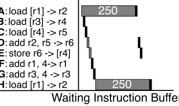
2.4 Waiting Instruction Buffer
Waiting InstructionBuffer (WIB) [44] differs from Runahead in that it attempts to obtain ILP as well as MLP under misses by retaining miss-independent work. To accomplish this, WIB places miss-dependent instruction in a new structure2 called the waiting instruction buffer as they pseudo-execute. The process of removing the miss-dependent instructions and buffering them for later re-execution is termed slicing out. Unlike the issue queue, the WIB does not support associative search and is not latency critical, meaning it can be made large. When a long latency miss returns, it and its dependent instructions aresliced in—re-injected into the issue queue for re-execution.
2It is possible to simply let the ROB double as the WIB since there is a one-to-one correspondence
A: load [r1] -> r2 B: load [r3] -> r4 C: load [r4] -> r5 D: add r2, r5 -> r6 E: store r6 -> [r4] F: add r1, 4-> r1 G:add r3, 4 -> r3 H: load [r1] -> r2
250
250
Waiting Instruction Buffer
Figure 2.12: Execution under WIB. Black boxes represent actual executions, while grey boxes represent pseudo-executions to propagate poison.
Figure 2.12 shows an example of execution under WIB. Load A and its dependents, D and E undergo pseudo-execution (grey box) to propagate poison and exit the issue queue. Removing these instructions allows G and H to enter the pipeline and execute. Executing H exposes MLP, improving performance. WIB does not need to re-execute independent instructions B,C, F, or G after A’s miss returns, providing some performance benefits from ILP.
WIB’s pseudo-execution/poison propagation allows the issue queue to scale by remov-ing miss-dependent instructions. However, the issue queue is only part of the problem— WIB does not scale the physical register file or load and store queues, and simply assumes they are very large. Since WIB only addresses part of the problem it is not, by itself, a complete load latency tolerant design.
2.5 Continual Flow Pipelines
2.5.1 Register management: Checkpoint Processing and Recovery
CFP scales the register file by replacing conventional, ROB-based register management with Checkpoint Processing and Recovery (CPR) [2]. CPR operates at the granularity of checkpoints, which are created at rename. Instructions are committed one checkpoint at a time and recovery is permitted only to checkpoints. CPR leverages the recovery restriction to aggressively reclaim physical registersbetweencheckpoints. At any point, CPR holds only those registers that are named in the active map-table or any map-table checkpoint, and those that are read or written by any un-executed in-flight instruction [52].
CPR reclaims registers out-of-order—a register is typically freed when the last instruc-tion that reads it executes, and execuinstruc-tion proceeds out-of-order. As a result, CPR cannot track free registers using a queue. Instead, it uses reference counting. Each register is associated with a reference count—a count of zero indicates the register is free.
CPR’s reference counting algorithm is simple. A register’s reference count is incre-mented when it is allocated to an instruction and written to the map-table, and decreincre-mented when it is overwritten and disappears from the map-table. It is incremented when an in-struction that reads or writes the register is dispatched to the issue queue and decremented when that instruction executes or is squashed. The reference count of any register that appears in a map-table checkpoint is incremented when that checkpoint is created and decremented when the checkpoint is freed.
A simple and efficient implementation of reference counting uses “unary” matri-ces [28, 69]. In a reference count matrix, each column represents a physical register and each row represents a resource that can hold a physical register, e.g., an issue queue entry or a checkpoint. A bit in the matrix is 1 if the given resource references the given physical register. A bitvector-style free-list is constructed by ORing together all the bits in a column. Registers are allocated from this free list using encoders.
copy, restore, or clear operations. These rows are actually stored as rows in an SRAM matrix. Other rows (e.g. the one corresponding to the rename map table) require manipu-lation of individual bits and are implemented as latches.
2.5.2 Slice Management and Processing
While CFP’s slice buffer is similar to a WIB, it has two major differences. First, it also captures miss-independent register inputs. This difference is significant as it decouples the dependent slice from the rest of the program. This decoupling means that miss-dependent instructions can release their input registers as if they had executed, allowing CPR to reclaim them.
The second difference is that CFP’s slice buffer is maintained in execution order, while WIB is maintained in program order. In CFP, instructions are allocated slice buffer entries as they slice out of the issue queue. A direct benefit of this allocation is that the slice buffer only needs space for miss-dependent instructions, making it smaller than WIB. The downside to tracking the slice in execution order arises when outstanding misses return and instructions must be re-injected into the window to re-execute.
to the destination physical register number originally assigned at rename.
Physical-to-physical renaming has several disadvantages. First, it requires the large physical-to-physical map table. Second, it holds registers live for artificially long dura-tions. Registers are only clobbered in the physical-to-physical map table when the slice buffer traversal encounters a younger instruction which wrote the samephysicalregister. It is possible for the slice map table to hold every available physical register, requiring a squash to break the deadlock3.
2.5.3 Load and store management
CFP scales the load and store queues through the use of hierarchy. For the load queue, CFP uses a large set-associative load queue in conjunction with a conventional fully-associative load queue. In this hierarchical design, the youngest loads are placed in the fully-associative queue. When the fully-associative queue’s capacity is exhausted, the oldest load in the queue is moved to the set-associative load queue.
Allocating an entry in the set-associative load queue requires the load’s address to be known to determine the correct set. If the appropriate set is full, then the load remains in the fully-associative load queue, and dispatch stalls. If the load’s address is not known, it is simply removed from the fully-associative queue and dispatch continues. In this situation, an entry in the set-associative queue is allocated when the load’s address becomes known. At that time, if the appropriate set is full, the load must wait until older loads commit, making space available. If the stalling load is in the oldest checkpoint, this will never happen, so deadlock is avoided by squashing checkpoints until either the required set has space, or the load in question is itself squashed.
The problem with CFP’s set-associative load queue design is that it can significantly inhibit performance. As the window grows and more loads occupy the set-associative load
3CFP proposes to reserve a pool of physical registers for re-renaming to avoid this problem.
queue, the liklihood of set-conflicts increases. These problems are magnified with miss-dependent loads of unknown addresses. These loads will only re-execute and determine their address after the miss they depend on returns. At this point, many younger loads will have executed, causing a high probability of a full set. If the set is in fact full, these old loads likely require squashes to make forward progress—not only hurting performance, but also wasting energy.
CFP also uses hierarchy to manage stores, with two proposed designs for secondary store queues. The first is a large associative queue with an access latency that matches that of the L2 [2]. To avoid accessing the secondary queue on every load—and effectively increasing load latency to L2 latency—the secondary queue is guarded by an address-indexed Bloom filter called the Membership Test Buffer (MTB). Load latency elongates to L2 latency only on an MTB “hit.” This design performs well. Its disadvantage is the area and dynamic power cost of the secondary queue.
simple, their associated management algorithms—which are required to detect forwarding violations—are complex.
2.6 KILO- and Decoupled KILO-Instruction Processors
KILO-Instruction Processor [19] is another load latency tolerance design. KILO scales the issue queue in a manner similar to WIB and CFP—it buffers miss-dependent instruc-tions in a non-associative structure until the miss they depend on returns. KILO calls this structure a Slow Lane Issue Queue (SLIQ).
KILO scales the register file using a combination of virtual registers and reference counting. At rename, logical registers are mapped to virtual registers—a namespace larger than the set of physical registers. The virtual register name is then re-mapped to a physical register when the instruction is actually ready to execute. KILO reference counts these virtual register names to determine when they can be reclaimed, and reclaims the underly-ing physical register at the same time. KILO does not consider the implementation details of this register management scheme. If this scheme were implemented using a reference counting matrix, the matrix would be quite large. It would need columns equal to the number of virtual register names, and would need one row per slow lane issue queue entry as well per conventional “fast lane” issue queue entry.
For the load or store queues, KILO cites various prior proposals, including those used by CFP, and states that any would be satisfactory.
2.6.1 Decoupled KILO-Instruction Processor
instructions leave the Cache Processor, they are placed into the Long Latency Instruc-tion Buffer (LLIB)—a FIFO queue which chains the out-of-order Cache Processor to an in-order Memory Processor. LLIB instructions capture their ready register input val-ues as they exit the Cache Processor, so that the Memory Processor’s execution is self-contained. D-KIP maintains precise register state in the Cache Processor using a series of register checkpoints. These checkpoints contain register value (not mappings), and miss-dependent instructions whose values appear in them are flagged to update the checkpoint when they execute on the Memory Processor. D-KIP scales the load and store queues using hierarchy. However, it arranges its hierarchy differently from CFP, using miss-dependence or independence rather than age to determine hierarchy level [59].
On disadvantage of D-KIP is excessive copying of register values. Another disad-vantage is the complexity of implementing register checkpoints that support incremental updates. A third disadvantage is that the only value communication from the in-order Memory Processor to the out-of-order Cache Processor comes in the form of restoring register checkpoints. Consequently, instructions executing in the Cache Processor may appear to be miss-dependent and re-execute on the second processor, even if the miss they depend on has already returned and their input values are known in the Memory Pro-cessor. Delaying this communication not only causes extra re-executions, but also can increase the branch mis-prediction penalty. Neither KILO nor D-KIP is capable of toler-ating the latency of dependent load misses.
2.6.2 Scalability of Load Latency Tolerant Designs
The slice buffer of load latency tolerant designs like CFP has two scalability benefits compared to the issue queue and register file. The first benefit is that it only needs to hold miss-dependent instructions. Figure 2.13 shows the percentage of instructions which are miss-dependent (i.e., ever poisoned).
0 10 20 30 40 50
% Miss-dependent Instructions
cactus gems lbm milc soplex spnx zeusmp libq mcf MEM AVG
Figure 2.13: Percentage of instructions which are miss-dependent.
0 10 20 30 40 50 60 70
Slice Buffer Issue Queue
Register File
64 256 512 1024 2048
(416) (1664) (3328) (6656) (13312)
Read Energy (pJ)
Slice Buffer Capacity (Effective Window Size)
Figure 2.14: Scalability of a slice buffer versus the scalability of an issue queue and register file. In addition to the size of the structures, the x-axis is labeled with the effective window size given by that slice buffer capacity, assuming 15% of instructions are miss-dependent.
associatively searched. Figure 2.14 shows the per-instruction read energy of the slice buffer and the issue queue4. AnS-entry slice buffer is modeled as four S/4-word 156-bit RAMs with one read port and one write port. Each entry holds a 64-156-bit instruction, a 64-bit (captured) data value, an 8-bit load/store queue index, an 8-bit physical register number, and a 12-bit instruction sequence number. The x-axis shows the capacity, but also lists the effective window size for the corresponding slice buffer size, assuming the average percentage of miss-dependent instructions (15.4%).
A 256-entry slice buffer requires about the same energy per read as a 36-entry issue queue requires per search. However, the slice buffer is only accessed by miss-dependent
4This graph ignores the fact that many of these issue queue sizes require changing the voltage or clock