FUZZY BASED AUTONOMOUS ROBOT FOR AVOIDING
OBSTACLES
Dr.S.V.Manisekaran
1, M.Ramaraj
2, J.Mohamed Yousuff
31
Assistant Professor,
2,3PG Scholar Department of Information Technology
Anna University Regional Centre, Coimbatore (India)
ABSTRACT
This project is to develop an autonomous robot with four wheel drive. It is capable of negotiating the obstacles with a leg motion mechanism. When the obstacles are encountered, wheels are lifted and moved ahead in a stepping like motion and lowered back down. It can also avoid any obstacles by changing the path by using fuzzy logic and path planning. When the vehicle encounters terrai n intractable by leg motion, with its current posture, the vehicle change its posture until it can traverse the terrain. Many robots are developed for industrial use, and home use Autonomous robots are characterized by their ability to execute tasks deprived of any human intervention. Decision making requires full or partial knowledge of the surrounding environment, or workspace, in which the agent is operating. Recent advances in sensor technology have enabled the use of reliable multisensory perception systems. Uncertainty in the perception stage leads to accumulated localization. Processing of collected data and accounting for errors is essential for accurate mapping and localization. When some interrupt occurs, it should take the correct decision using path planning algorithm and SLAM (Simultaneous Localization And Mapping). This autonomous robot which is not controlled by joystick, instead it is controlled by brain computer interfaces for intended movements from electrical activity. This robot will tolerate some rough environments. Some examples of access barriers are steps at the entrances of buildings, curbs without ramps and gutters and holes in the road.
Index Terms: Gait Algorithm, Mobility Performance, Obstacle, Personal Mobility Vehicle,
Autonomic Robotic Wheel Chair, Rough Terrain, Terrain Topology.
I. INTRODUCTION
A Robot is mechanical or virtual intelligent agent that can perform tasks automatically guidance, typically by
remote control. The robot is usually an electromechanical machine that is guided by computer and electronic
programming. Robotics is the branch of technology that deals with the design, construction, operation,
manufacture and application of robots and computer systems for their control and information processing.
Robotic technology is used to deal with hazardous situation such as dealing with suspicious packages and
collection of intelligence. Sensors are used to sense the environment and give useful feedback to the device.
Robotics can be described as the current pinnacle of technical development. Robotics is a science using the
continuing advancements of mechanical engineering, material science, sensor fabrication, manufacturing
techniques, and advanced algorithms.
Proximity sensor easily detects the presence of any object. Our robot will follow the technique of bat to detect
obstacle in its path. If the receiver receives this reflected wave then we can be sure that there is an obstacle in front of
calculated. Since the speed of the sound wave .we can calculate the distance of the obstacle. This is done in two parts.
The first part consists of taking visual information of the object. Camera is used to take images and we would use
various image processing techniques to extract the object from the image. The second part consists of taking the range
information of the object. . A photo electric sensor is a device used to detect the distance, absence, or presence of an
object by presence of an object by using a light transmitter, often infrared, and a photoelectric receiver. The principle
behind infrared automatic door (or) find the obstacles sensors is the transmission and receiving of infrared light. An
element known as a light emitting diode (LED) transmits active infrared light, which is reflected on the floor and
received by an optical receiver known as a photo diode (PD).
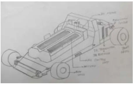
1.1 Deviate the Vehicle
The most common barriers to widespread autonomous robot use are uneven footpaths, uneven ground, and
curbs. Based on this, it is clear that an ability to negotiate uneven terrain and obstacles approached at an oblique
angle would greatly expand the usability of autonomous robots. Therefore, we have developed a autonomous
robot named RT-Mover P Type 3, which can traverse steps approached not only from the front, but also at an
oblique angle. The main feature of our development is its leg motion mechanism. The ability to lift each wheel
up and down in accordance with the terrain is paramount to the ability to traverse steps approached at an oblique
angle. This is a autonomous robot has the lowest number of actuated axes among currently available
four-wheel-based mechanisms capable of lifting each wheel up and down independently while keeping the seat part
horizontal. This means that the leg motion mechanism of our autonomous robot is among the simplest. The
general strength of our autonomous lies in its energy efficiency due to the wheel-based mechanism, as well as
the simplicity of the mechanism.
1.2 Sensing the Obstacles Using Proximity Sensor
These are possible motions for enhancing static stability, and find that only the steering axis on the leg motion
side can be used to enhance static stability for the following reasons: The support-side steering axis should
already be turned all the way in one direction or another in order to maximize stability, and the pitch axis is
controlled to maintain the seat horizontal. Thus, to increase the static stability margin, the steering axis on the
leg motion side is rotated around the leg motion wheel.
1.3 Controlling Tilt in Some Terrains
Localization and Mapping have all been applied in robot for path planning. It is proposed of that artificial forces
repelled the robot away from the obstacles and attracted it towards the goal position. Sensor based reactive
planning methods have been proposed. Control based methods require formulating accurate models for the robot
and the environment which can be a rather daunting or terrain task
1.4 Automating the System
An autonomous vehicle, also known as a driverless car, driver-free car, self-driving car, or robot is an
autonomous vehicle capable of fulfilling the human transportation capabilities of a traditional vehicle. As an
autonomous vehicle, An autonomous robot is a robot that performs behaviors or tasks with a high degree of
autonomy, which is particularly desirable in fields such as space exploration, cleaning floors, mowing lawns,
and waste water treatment. It can find the position of the vehicle and navigate their own routes to destinations on
Computing safe and unsafe areas on the surface within the field of vision.
Computing optimal paths across the safe area towards the desired destination.
Driving along calculated route.
Repeating this cycle until either the destination is reached, or there is no known path to the destination.
1.5 Path Planning
Planning is not only one of the fundamental problems in robotics, it is perhaps the most studied. Early efforts to
develop deterministic planning techniques showed that it is computationally demanding even for simple
systems. Exact roadmap methods such as visibility graphs diagrams adaptive roadmaps attempt to capture the
connectivity of the robot search space. The use of graph search methods involves discretization of the
workspace and their performance.
Degrades in a high dimensions. Efficient discretization can be achieved on the expense of completeness and
high-resolution discretization is computationally expensive. The emergence of novel computational methods
inspired their use in path planning. Methods such as Fuzzy Logic Control , Neural Networks, Genetic
Algorithms, and Simultaneous
II.RELATED WORK
A number of researchers have developed schemes for controlling leg motion of a leg-type machine along with
consideration of footstep width and vehicle stability Cohen et al (1989). Our research is similar in that our
algorithm adjusts vehicle posture such that leg motion can be carried out by considering footstep width and
vehicle stability. However, our PMV (Personal Mobility Vehicle), which has fewer leg motion drive axes than
do conventional leg-type machines, is different in that it requires the support points bearing the vehicle weight
to be shifted in order to secure stability for leg motion. In contrast, a leg-type machine can utilize its large
number of degrees of freedom to easily adjust its center of gravity without shifting the support points in order to
increase its stability Chapelle et al (2008). Because of this difference, the gait algorithms adopted for
conventional leg-type machines cannot be utilized here. Also, while reference does discuss research on a mobile
platform that is structurally similar to our PMV (Personal Mobility Vehicle), the discussion extends only onto a
verification of its mobility under a fixed gait. Therefore, the proposed algorithm in this paper is completely new,
and we provide the first evaluation of a gait algorithm through both experimental and numerical analysis, which
is expected to be extremely useful for research on PMVs of this type Chapelle et al (2008). we configured the
vehicle to provide adequate mobility stably with a simple mechanical structure, taking a four wheel model as the
base. Our PMV (Personal Mobility Vehicle) can move in two modes: a conventional wheel mode and a leg
motion mode. Shows that our PMV can maintain the horizontal orientation of the seat.when one side wheel is
on an obstacle in wheel mode, and perform the pivot turn and the sideways motion by aligning its wheels with
90 steering angles. During wheel mode, the seat of the vehicle is kept in the horizontal position through
feedback controls of the pitch axis and front and rear roll axes. The vehicle has a total of 13 drive axes are four
driven wheels of four axes at front and rear steering axes. Then two axes at front and rear roll axes. Next two
axes at a pitch axis a seat slide mechanism axis and another is footrest mechanism .The footrest mechanism
merely serves to move the footrest out of the way when moving the front wheel leg and is irrelevant to the gait
the gait algorithm Nakajima (2011). Upon excluding the above axes from consideration, we can say that this
mechanism is rather simple because it consists of only four drive axes, four driving wheel axes, and front and
back steering axes Nakajima (2011).
Planning is not only one of the fundamental problems in robotics LaValle (2006), and Choset (2005). It is
perhaps the most studied Latombe (1999). Early efforts to develop deterministic planning techniques showed
that it is computationally demanding even for simple systems Reif (1979). Exact roadmap methods such as
visibility graphs adaptive roadmaps, attempt to capture the connectivity of the robot search space. Cell
decomposition methods, in which the workspace is subdivided into small cells, have been applied in robotics
Search algorithms such as Dijkstra (1959). Find an optimal solution in a connectivity graph, whereas are
tailored to dynamic graphs. Hart et al (1968). The use of graph search methods involves discretization of the
workspace and their performance degrades in high dimensions. The work in generates state lattices using
motion primitives and combines them with graph search algorithms but, it still suffers from undesirable
discretization. Efficient discretization can be achieved on the expense of completeness and high-resolution
discretization is computationally expensive Pivtoraiko (2011) and Beom et al (1995).
The emergence of novel computational methods inspired their use in path planning. Methods such as Fuzzy
Logic Control Beom(1995), Martinez Alfaro(1998) and Gomez Garcia et al(2002). Neural Networks Janglova
(2004), Genetic Algorithms, Gerke(1999), Yanrong et al (2004). Ant Colony Optimization Garcia et al(2009)
and Simulated Annealing have all been applied in robot path planning. Khatib (2010) and Maekawa et al
(2010). Those are proposed of the potential field method such that artificial forces repelled the robot away from
the obstacles and attracted it towards the goal position. Potential fields were also applied for mobile robots in,
however they suffered from falling into local minima and performed poorly in narrow regions. Koren and
Borenstein (1991). Sensor based reactive planning methods have been proposed. Control based methods require
formulating accurate models for the robot and the environment which can be a rather daunting task Howard
(2007) and Kelly et al (2012).
It is pointed out in that technologies required for a general autonomous UGV(Unmanned Ground Vehicle) can
be divided up into five areas: mobility, localization, navigation, planning, and communication Durrant Whyte
(2001). The relationship between them is depicted. It is deals with the vehicle mechanism design, the motion
control technique, and the interaction between the vehicle and terrain. It is concerned with the kinematics and
dynamics of the vehicle platform and the control algorithms for the vehicle as well as all actuators outfitted on
the vehicle to obtain the desired motion on a certain terrain. It is allows the vehicle to be connected with human
operators and other vehicles or systems. Whether the vehicle is fully autonomous or not, it requires a
communication link to co-operate with other vehicles or the base station in many missions. It is related to
estimation of the vehicle position and attitude in a fixed frame: for example, an earth-fixed coordinates system.
It is concerned with robust algorithms for more accurate estimation to deal with sensor uncertainties. Taking
information from internal and external sensors as inputs, its outputs affect both navigation and mobility
processes Durrant Whyte (2001).
It handles information obtained from environment sensors to build up a map of the environment. The
representation of the environment is then used to control the vehicle in small area around the current vehicle
position in order to follow a trajectory defined in a planning process. It also manages obstacle detection and
avoidance. It is makes use of all known information from prior maps, mission goals, sensory and control
the incomplete knowledge of the world in outdoor missions, the vehicle must use the environment information
gathered along the local path to update or rebuild the trajectory Durrant Whyte.
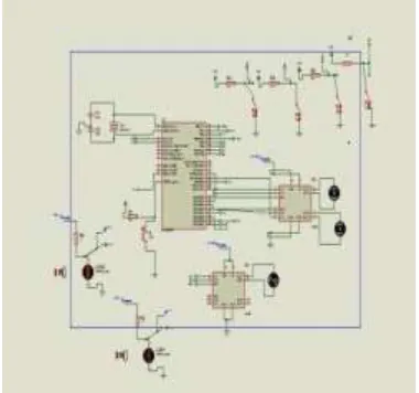
III.SYSTEM ARCHITECTURE
Architecture diagram is the representation of a system in which the principal parts or functions are represented
by blocks connected by lines that show the relationships of the blocks. It is typically used for higher level, less
detailed description aimed more at understanding the overall concepts and less at understanding the details of
implementation.
Figure 3.1 System Architecture
The figure 3.1 represents the architecture of proposed system. Autonomous robot is designed to be operated
remotely. The major components used are IR sensors in the front and back wheels to sense the environment.
This sensed data is given to the processing unit having 16F877A Micro controller. The function of this
processing unit is find the presence of objects or any obstacles present in that environment using those sensed
information. The type of obstacle is identified whether it is small or large. If it is small obstacle then the
autonomous robot tilted so that the DC motor starts rotate. It should stop its rotation when the wheels got
stabilized. Otherwise it should deviate its path.
IV AUTOMATIC MOVES
This module is used to describe the movement of the autonomous robot. Here the movement of the autonomous
robots is made automatically which avoids the human effort used for controlling the robot.
4.1 PATH SENSE AND AVOIDING OBSTACLES
While moving there should be more obstacles in the path of the autonomous robot. The obstacles may be small
or large. Hence it is necessary for the autonomous robot to find those obstacles while moving in its path. Thus
this module sense the path of the autonomous robot using SLAM (Simultaneous Localization And Mapping)
algorithm and identifies the obstacles if present.
4.2 SMALL OBSTACLE MOVING
The obstacle found in the path of autonomous robot is small, then the autonomous robot should tilts
automatically for passing that obstacle. So that the movement of the autonomous robot continous smoothly.
4.3 LARGE OBSTACLES DEVIATION
This is the final module which is used to deviate the path of the autonomous robot if the large obstacle is found
in its path. The deviation of the path is identified using the SLAM algorithm which is based on finding the X, Y
and Z axes coordinates.
IV. RESULTS
This shows the rotation of wheels when the switch is ON. The stability of wheels is identified by the rotation of
the DC motor.
Figure 4.1 Design of the simulation output.
Figure 4.1 is the simulation output design. Vehicle will move forward when first switch is ON , likewise the
vehicle will move backward if second switch is ON, vehicle will move right side and left side when third switch
is ON. Light Dependent Resistor will be due to the light source. If light source is low the resistance will be high.
If two light source is not in equal voltage , the balance motor will be rolling to make the two light source to be
balanced.
V CONCLUSION
Autonomous robots are used in many applications. It has established its success in solving the intricate problem
of robot leg motion. Here we developed an autonomous robot which moves automatically. The proposed system
continue moving independent of the terrain. While moving it finds its obstacles and avoid those obstacles using
the SLAM(Simultaneous Localization And Mapping) algorithm. This method have been proposed to improve
the efficiency of planning and the quality of plans. Simulation is done in the Proteus 8 environment by using
fuzzy and wheel. Measure the wheel motion angle and controlled by wheel motion mechanism
Design robot with four wheels. Photo electric sensor placed at front wheel. For forward and backward leg
motion dc-motor is used. Detection of obstacles is done using various sensors, and determined whether to
traverse or deviate from it. In this phase, The path sensing module is simulated using Proteus software and the
rotation of the DC motor is observed which shows that the wheels are stable. In the next phase I will implement
REFERENCES
1. Atrash A., Boucher P.,W. Honore W.,Kelouwani S, Nguyen H., Villemure J. (2013), ‘Design and
validation of an intelligent wheelchair towards a clinically functional outcome’, Papers from the AAAI
Spring Symposium. Team School of Computer Science, McGill University, Montreal, Quebec,
Canada.
2. Atrash A., and Pineau J. (2009), ‘A bayesian reinforcement learning approach for customizing human
robot interfaces’. In International Conference on Intelligent User Interfaces (IUI).
3. Avis Cohen H. ,Yasuhiro Fukuoka H.S.(2003), ‘ Adaptive Dynamic Walking of a Quadruped Robot
on Irregular Terrain Based on Biological Concepts’, The International Journal of Robotics Research,
Vol. 22, No. 2, pp.187-202.
4. Boninger M. L , Chan L , Cowan R. E. , Fregly B. J, , and Reinkens Meyer D. J., RodgersM. ( 2012) ,
‘Recent trends in assistive technology for mobility’, Journal of Neuro Engineering and Rehabilitation
vol. 9, no. 20, pp 167-186.
5. BouzgarrouB.C., and Chapelle F.,FaurouxJ.C.(2008), `Experimental validation of stable obstacle
climbing with a four wheel mobile robot Open WHEEL i3R’, Conference on Mechanical Related
Papers, pp. 171-178.
6. Cohen A. H., Fukuoka Y., Kimura H.( 2003), `Adaptive dynamic walking of a quadruped robot on
irregular terrain based on biological concepts’, The International Journal of IEEE Access, vol. 22, no
3-4, pp. 187-202.
7. Halme A., Kettunen I., Leppanen I.,Suomela J. and Ylonen S. (2003), ‘interactive human like service
robot for outdoor applications’, The International Journal of Robotics Research, vol. 22, no 7-8, pp.
627-640.
8. Harrington B. D.,and Voorhees C. (2004), ‘The challenges of designing the rocker-bogie suspension
for the Mars exploration rover’, Aerospace in Mechanical Symposium, Houston, pp. 1-12 .
9. Lindemann R. A., Reid L., Voorhees C. (1999), ‘Mobility Sub system for the Exploration Technology
Rover’, Aerospace Mechanisms Symposium, pp. 125-140.
10. Montgomery J. F.,SaripalliS.,andSukhatme G. S.(2003), ‘Visually guided landing of an unmanned