DEVELOPMENT OF A HIGH SPEED CORNERING
ASSIST
Pankaj. K. Singh
1, Naman Taneja
2, Adarsh Gaurav
3, Ankit Behl
4,
Vikas Singh
5.
1
Assistant Professor,
2,3,4,5Student , Department of Mechanical and Automation Engineering,
Amity School of Engineering & Technology, Bijwasan, New Delhi, (India)
ABSTRACT
With the advent of the automobile era, the accident occurring due to the human negligence and vehicle
malfunction emerged as a potential threat to our loved ones. Due to high speed cornering, rollover accidents
take place. To minimize such accidents, a new economical device that can be used to reduce vehicle venerability
to rollover is high speed cornering assist device.
The high speed cornering assist device shall search as an altering device for the driver. If these signal lies in the
zone to trip the vehicle, the driver shall be altered, so that driver could take the necessary action to prevent the
rollover. The device consist of simple mass and spring system whose motion about mean position is monitored
by proximity sensor which actuate to an alarming device hence to alert the drivers to take necessary measure to
control their vehicle to avoid accidents.
Keywords: Cornering, High Speed, Safety, and Rollover.
I. INTRODUCTION
Now-a-days, accidents due to rollover are fatal and are increasing at a high pace. To minimize such accidents, a
new economical device that can be used to reduce vehicle venerability to rollover is high speed cornering assist
device.
The device is named as high speed cornering assist (HSCA) and it shall serve as an alerting device for the
driver. The device will measure the angle of inclination of vehicle while cornering and transduce these
measurements into the electrical signals to actuate a buzzer. If these signal lies in the risk zone that might lead to
tripping of the vehicle, the driver will be altered, so that he can take the necessary actions to prevent the
rollover. The device is made intelligent by incorporating “switch off” action that will be initiated at the starting
of the high risk zone. Under such circumstances the device will cut the engine supply so that the vehicle is
retarded.
The inspiration behind this research is lack of economical devices available for heavily loaded automobiles like
trucks, wagon, Lorries etc. Number of accidents has occurred in which the HGVs have rolled over as the driver
wasn’t aware of the tilt of the vehicle and hence lost control. The available devices are rare and expensive as
they modify the suspension system to facilitate the braking action or it may vary the engine output regulating the
caused due to tripping at the corner. In 1997, Yoshimi Furukawa and Mastao Abe also emphasized that there is a
need to further propose control laws based on deeper observation and understanding on the tire and vehicle
dynamics so as to ensure safety [1].
The device being proposed can be a part of any vehicle running on road, as its installation doesn’t need any factory modifications. It also doesn’t alter any other system nor voids the warranty of the vehicle. The device is
cost effective as it can either work on the simple principle of potentiometer or on a proximity sensor. The device
consist of simple mass and spring system whose motion about mean position is transduced either by a
proximity sensor or by variably conductive devices, which actuates an alarming device which alerts the driver.
II. LITERATURE REVIEW
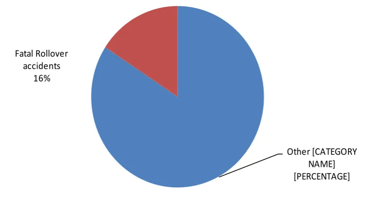
According to NHTSA (National Highway Traffic Safety Administration, US), more than 280,000 rollover
accidents each year & out of these 16% are fatal and leads to death of our loved once [2](Figure 1).
Figure 1. Fatal Rollover Accidents
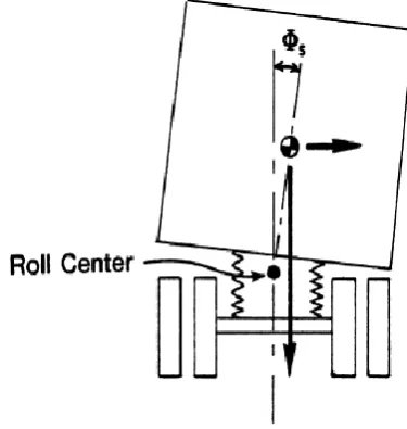
A vehicle roll over is among the worst things that can happen on road. The chance for a rollover are more in
taller and narrower vehicle having high center of gravity like the SUVs, pickups, vans and trucks etc.
[3].A rollover is a type of vehicle accident in which a vehicle tips over onto its side or roof, the lateral forces
increase with speed and also with rapid change of direction as when driver makes too sharp a turn one way and
over corrects the other one (Figure 2). A single-vehicle rollover is usually not caused by a steering maneuver.
Instead the vehicle usually has to “trip” on something such as when its swerves into curb, potholes, or soft
roadside shoulder. The government has estimated 95 percent of rollover results from trips. As the number of
accidents increases, so is the concern for the safety of passenger leading towards the invention of devices which
can prevent rollover and assist the driver. The technologies available are expensive and works on the suspension
system actuates the brakes to slow down. Studies suggest that electronic stability control systems can reduce the Other [CATEGORY
NAME] [PERCENTAGE] Fatal Rollover
chances of fatal injuries by 35% [4]. In 2002, Aleksander Hac suggested a simple yet insightful model to predict
vehicle propensity to rollover is proposed, which includes the effects of suspension and tire compliance [5].
Figure 2. Location of Roll Center in Vehicle
Technologies available in nowadays vehicle are as follows.
Cornering brake control
Cornering brake control or CBC is an automotive safety system introduced by car makers like BMW and
MERCEDES BENZ (ESP Dynamic Cornering Assist and Curve Dynamic Assist). It is a further development
and expansion of the anti-lock braking system, designed to distribute braking force during braking whilst
cornering.
Active trace control
The Active Trace Control is a control system which can apply braking automatically to each wheel, helping to
keep the vehicle on the cornering line as steered. The system helps drivers smoothly maintain control, so they
are able to relax and drive around corners more confidently.
Vehicle stability assist
The Vehicle Stability Assist (VSA) was introduced by Honda to its vehicles in 1997. The term is Honda's
version of Electronic Stability Control (ESC), an active safety feature developed to
correct oversteer and understeer by using several sensors to detect loss of steering control and traction while
simultaneously braking individual wheels to help the vehicle regain stability.
III. OBJECTIVE
The High speed cornering assist is designed with the following objectives:
To prevent the increasing number of accidents due to rollover.
Simple and effective design alerting the driver in the position of roll over.
Economical
Can be installed easily into any vehicle
IV. METHODOLOGY
As the vehicle takes a sharp turn, there is possibility that the vehicle will rollover, this happens because the
forces acting on it undergo significant variation. The driver also feels these forces when a vehicle turns around a
corner. These forces result in the tilting of the driver as well as the car, the above concept is based on the
“Newton first of motion” which defines the term “inertia”. In order to study the cornering scenario all the forces
are considered, acting on the vehicle while undergoing a turn.
On a turn, as the vehicle moves the automobile body and its suspension system tilt’s a little to attain the
stability. This case is similar to the banking of road in which the vehicle is kept uniform throughout and the tilt
or inclination is provided on to the roads which prevents the slipping and rollover of vehicle while taking a turn.
The centrifugal force acts outwards from the vehicle whereas the friction force acts towards the center of
curvature of the curve road and a balance between these two forces help to keep the vehicle stable on the road.
In this the roads remain flat but due to turning the suspension inclined at an angle so that the grip on the road
remains constant. So this inclination of suspension can be calculated by the formula given by the NHTSA
(National Highway Traffic Safety Administration, US). After the determination of this angle, the body can be
assumed to be inclined at this angle and further all the forces acting on it can be realized.
To calculate these forces, considered a quassi static rigid body inclined at an angle referred above. Then the
basics of “Newton equations of motion” are woven with the vehicle dynamics and with the concept of rollover
including the behavior of forces on banking of roads to obtain the necessary characteristic values.
The calculations are made with respect to the center of gravity (COG), and all the forces are assumed to be
acting on it. Further the motion of the central mass, placed in our device is studied along the longitudinal axis.
This motion then forms the basis of the scale of the proposed device and the necessary configuration of the
proximity sensors or the variably conductive plates. In addition to this we tried to find the necessary placement
position.
V. DESIGN
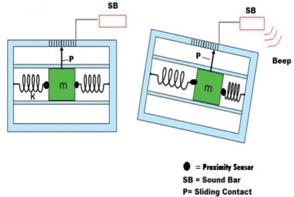
The device consist of a central mass connected to spring on both the sides, this arrangement is enclosed in a
casing facilitating motion along the longitudinal axis only. The surface of casing is aluminum metal upon which
the mass can slides to and fro. The plate has a friction lining so that any random motion of mass about the mean
Figure 3. Proposed Design of Device
There are two ways of transducing the motion of the central mass, the first being the conventional variably
conductive plates, that transfer current depending upon the resistance of the contact region. In the other way,
two proximity sensors can be placed upon the vertical surfaces of the mass. These sensors shall measure the
distance from the fixed ends. In both the cases a suitable amount of insulated zone or parameters are kept that
help us in differentiating between the risk zones.
The device design is unique and can be installed in any vehicle and is needed to be placed inside the passenger
compartments above the center of gravity, so it is required to be concise and light. The position of device
determine the spring constant and the critical angle of rollover is also height dependent, so every device should
be calibrated for specific vehicles independently.
VI. CALCULATIONS
The force acting on the automobile will taking a turn is considered in which the centrifugal force away from the
center of curve of the curved road and the friction force acts towards this center.
6.1 Assumption to be made for calculations
The forces are assumed are for a quassi static rigid body.
The vehicle travels with a uniform speed of 60 Kmph.
The vehicle takes a 90 degree turn.
Figure 4.Path While Cornering
Critical angle of inclination while cornering after which rollover occurs ( )
(Figure 5, 6)
Figure 5.Force Due to Lateral Acceleration
H
T
2
tan
1max
Figure 6. Inclination of Vehicle
As per the above formula [2], critical angle of rollover is found out for a Honda civic car, a minivan and a truck.
For each of the critical angle, a safe designing angle is selected to maintain the necessary factor of safety (Table
1).
Table 1. Critical and Designed Angles for Various Vehicles
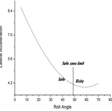
The selection of a designing angle is based upon two factors, the first being the safe zone limit given by the
lateral acceleration vs. rollover angle and the second being the mass of that a vehicle carries under maximum
load. So for the assumed values the graph for lateral acceleration vs. rollover angle in Figure 7
Figure 7. Variation in Lateral Acceleration with Roll Angle
Vehicle Type Critical Angle of rollover Designing Angle
Honda Civic 48.5599° 35°
Mini Van 41.98° 30°
The calculation for force acting on the central mass of the device:
Resultant forces on vehicle in Figure 8.
Figure 8. Resultant forces on vehicle
Acceleration of the mass block
cos
sin
2
g
g
r
v
M
F
a
a = acceleration, F = force, M = mass, v = velocity of vehicle, μ = friction coefficient,
g = acceleration of gravity, θ = angle of inclination
Time elapsed during turn
v
R
t
/
t = time taken to take a turn, R= radius of curvature of road, v = velocity of vehicle
Velocity which with mass slides
at
u
v
v =velocity with which the central mass slides
Distance moved by Mass
a
u
v
s
2
2 2
s = the displacement of mass along the longitudinal axis
kx
ma
k = spring constant, x = displacement
By using the above mentioned equations the following Table 2 was prepared.
Table 2 – Results
Sensitivity of the device
Sensitivity of the device is the ratio between the changes in the output of a device to the corresponding change
in the measured variable. For a good device or process, the sensitivity should always be high, thus producing
higher output amplitudes.
For a quassi static body, under consideration the variation in distance travelled by the central mass per unit
change in the angle of inclination gives the sensitivity. The variation is shown as below.
(a) Sensitivity graph
Variation in Sensitivity with respect to θ is shown in Figure 9.
Name Angle (Degree)
Acceleration of central mass (m/sec2)
Velocity with the mass slides (m/sec)
Distance moved by the central mass (m)
Civic 35 4.9096 8.3230 7.05487
Mini Van 30 5.35089 9.0711 7.68898
Truck 25 5.868951 9.9494 8.43341
Figure 9. Variation in Sensitivity with respect to θ
(b) Conclusions from the graph
1. The change in displacement of central mass is negative and turns to positive when the angle is very high.
2. For the given value of , used for the design, the change in displacement will always be negative.
Negative change implies that the displacement for a 5° change is more than for a 10° change.
Following outcomes from the graph will force to introduce time delays in the device, so that the buzzer gets
activated at a particular time only. Hence, providing a high sensitivity range to the device.
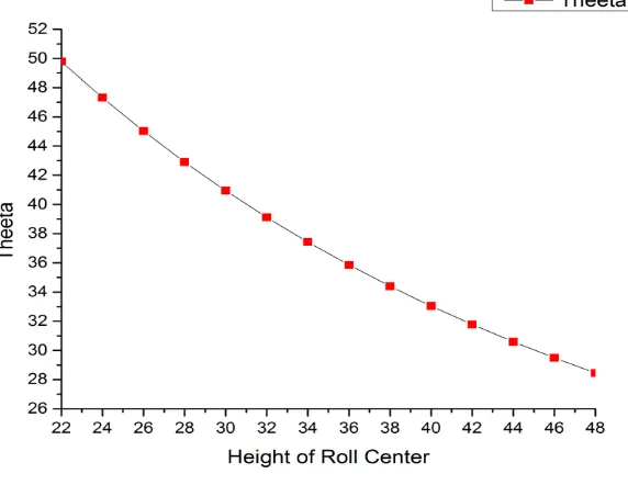
Position Related Adjustments needed
Currently the device is assumed to be kept at the Center of Gravity (COG), but practically it can’t be placed over
there so it will result in the variation of and all the variables. The variation of Height vs. Angle of
Inclination is shown in Figure 10.
30
Figure 10. Variation in θ with change in Height of roll center
As we increase the height of placement, the critical angle will reduce correspondingly. Hence the device should
be placed and calibrated for to the Maximum height obtainable by the chassis.
VII. RESULT & FUTURE SCOPE
The device shall serve its rightful purpose and can be used for any vehicle, given the condition that it is calibrated for the vehicle’s maximum load and as per the height of placement. The proposed device has a non-
linear negative scaling i.e. the least value is present at the end of the scale. The springs used provides the smooth
movement of the central mass, hence result in accurate operation. Further this is just the start towards a greater
goal of producing low cost, efficient devices that could be implanted in vehicles that help in saving vehicles
from potential accidents. Moreover further research can be conducted to make the device linear and make it
more efficient. The proposed design of the device’s casing is in Figure 11.
REFERENCES
[1]. Furukawa.Y. and Abe, M., Advanced Chassis Control Systems for Vehicle Handling and Active Safety,
Taylor and Francis Vehicle System Dynamics Vol. 28, Issue. 2-3, 1997
[2]. Shivakumar, T. and Krishnaraj, R.K., A Conceptual Study on Drivers Psychology and the Surrealistic
Attitude of Drivers the Cause for Road Traffic Accidents, International Journal of Civil Engineering and
Technology (IJCIET), ISSN 0976 – 6308 (Print), ISSN 0976 – 6316(Online) Volume 3, Issue 2, July-
December (2012), IAEME.
[3]. Gillespie, T.D., and Ervin, R.D., Comparative Study Of Vehicle Roll Stability, A report submitted to U.S.
Department of Transportation Federal Highway Administration Washington in 1983.
[4] Burton, D. et.al, Effectiveness of ABS and Vehicle stability control system, Royal Automotive Club of
Victoria, 04/01 in 2004.
[5] Hac, A., Rollover Stability Index Including Effects of Suspension Design, SAE technical paper,