http://www.sciencepublishinggroup.com/j/mma doi: 10.11648/j.mma.20170205.11
ISSN: 2575-1786 (Print); ISSN: 2575-1794 (Online)
Assessment of the Accuracy of the
Multiple-Relaxation-Time Lattice Boltzmann Method for the
Simulation of Circulating Flows
Mohammed Ahmed Boraey
Mechanical Power Engineering Department, Faculty of Engineering, Zagazig University, Zagazig, Egypt
Email address:
To cite this article:
Mohammed Ahmed Boraey. Assessment of the Accuracy of the Multiple-Relaxation-Time Lattice Boltzmann Method for the Simulation of Circulating Flows. Mathematical Modelling and Applications. Vol. 2, No. 5, 2017, pp. 47-51. doi: 10.11648/j.mma.20170205.11
Received: September 23, 2017; Accepted: October 24, 2017; Published: November 20, 2017
Abstract:
The present work investigates the accuracy of the Multiple-relaxation-time Lattice Boltzmann Method (MRT LBM) in the simulation of flows with circulation. The flow in a 2Dlid-driven cavity is simulated using MRT LBM for a wide range of Reynolds numbers (100-1000) to assess its accuracy. The lid-driven cavity flow is selected because it is the standard benchmark problem for the testing of numerical methods. The calculated locations of the primary vortex center in addition to those of the two side vortices (lower-left and lower-right) are compared to the previously published results using different numerical techniques such as finite difference, finite element and single-relaxation-time LBM. The horizontal and vertical velocity profiles are also calculated. The results show that the MRT LBM has a superior accuracy compared to other numerical techniques especially for circulating flows.Keywords:
Multiple-Relaxation-Time, Numerical Accuracy, Lattice Boltzmann Method, Circulating Flow, Lid-Driven Cavity Flow1. Introduction
Computational fluid dynamics (CFD) numerical techniques has changed and varied dramatically in the past few years [1]. The reason for this is the diversity in the applications of the CFD [2-6]. Although continuum based CFD approaches like finite difference, finite volume and finite element relay on the solution of continuum governing equations (i.e. macro scale), other emerging techniques are looking at the same problems from a different scale. These can range from the micro-scale based methods like molecular dynamics to macro-scale ones like finite volume.
The Lattice Boltzmann Method (LBM) has emerged as a numerical technique dealing with the problems at the meso-scale [7]. This allowed the LBM to retain the advantages of the two scales (i.e. macro and micro) while avoiding their short comings. The LBM has been widely used for many applications including fluid flow [7,8], heat and mass transfer [9], multi-phase [10] and multi-component [11], non-Newtonian fluids [12, 13], fluid-structure interaction [14] and flow in porous media [12, 15] problems. The LBM has many
variants according to the target application. The two-relaxation-time (TRT) LBM and multiple-two-relaxation-time (MRT) LBM were invented to overcome the shortcomings of the standard single-relaxation-time (SRT) LBM [16-19].
For each emerging new computational technique, a set of benchmark cases has to be used to test the new model accuracy. The lid-driven cavity flow is the most widely used case for benchmarking numerical methods [20-23]. It involves high velocity gradients and strain rates in addition to circulation. Circulating flow is encountered in many applications and its modeling is more challenging than the unidirectional flow [24, 25]. For this reason, new numerical methods have to be tested for their accuracy using the lid-driven cavity flow case before being used for applications involving circulation.
2. TheMultiple-Relaxation-Time LBM
The standard LBM relies on solving the Boltzmann equation in a discretized form using a limited set of velocity directions. The discrete Boltzmann equation can be written as follows:
Δ , Δ , Ω (1)
is the particle distribution function along direction , is the lattice speed Δ Δ and Ω is the collision operator. For the used D2Q9 lattice the directional velocities are given by:
0,0 0 1,0 , 0, 1 1: 4
1, 1 5: 8 (2) For the SRT LBM Ω is replaced by the Bhatnagar– Gross–Krook (BGK) collision operator [26]. Due to many limitation of the standard SRT LBM, the MRT LBM is used instead. In the MRT LBM the collision operator is expressed as follows:
Ω . . !" (3) is a transformation matrix to transform the particle distribution function from the velocity space to the moment space . . The equilibrium distribution function !is also transformed to ! . ! . is the diagonal relaxation matrix.
# $ $ $ $ $ $ $
% 14 11 11 11 1 1 11 2 2 12 12
4 2 2 2 2 1 1 1 1
0 1 0 1 0 1 1 1 1
0 2 0 2 0 1 1 1 1
0 0 1 0 1 1 1 1 1
0 0 2 0 2 1 1 1 1
0 1 1 1 1 0 0 0 0
0 0 0 0 0 1 1 1 1'(
( ( ( ( ( ( )
(4)
* +, 0, - , -., 0, -/, 0, -0, -1, -1 (5) For the used D2Q9 lattice, the sonic speed is given by:
2 √53 (6)
The kinematic viscosity 6 is related to -1 by the following relation:
6 2.728 .9 (7)
The equilibrium particle distribution function ! is given by:
! : ; <1 3=.> 3?@ 3=.>
@
.3?A >.>.3?@B (8)
And the macroscopic density ; and velocity C are given by:
; , ∑ , (9) CE , F G,H ∑ E , (10)
3. The Lid-Driven Cavity Flow
The lid-driven cavity flow case is used as a benchmark problem to test the accuracy of the MRT LBM. The modeled geometry shown in Figure 1 consists of a square cavity with the top side moving to the right. The rest of the sides are stationary. The movement of the top surface causes a vortex to develop inside the cavity whose size, strength and location depend on the flow Reynolds number. At the two lower corners (left and right) two small vertices with a circulation in an opposite direction to that of the main vortex also develop. Their characteristics also depend on the flow Reynolds number. The location of the three vortices centers is used as a benchmark for the accuracy of the numerical method used to solve the problem.
Figure 1. The lid-driven cavity geometry and boundary conditions.
4. Results and Discussion
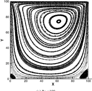
The MRT LBM is used in the simulation of steady viscous incompressible flow in a 2D lid-driven cavity at a range of Reynolds number between 100 and 1000. The flow Reynolds number is calculated based on the cavity width and the velocity of the top lid as a characteristic velocity. The streamlines for some of the cases are shown in Figure 2.
(b) Re=200.
(c) Re=400.
(d) Re=600.
(e) Re=800.
(f) Re=1000.
Figure 2. The steady state streamlines for different Re=100, 200, 400, 600, 800 &1000.
Figure 3. Tangential velocity profiles at x=50. Starting at the red semi-horizontal line for Re=100, 300, 500, 700 & 900.
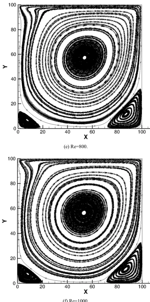
Figure 4. Vertical velocity profiles at y=50. Starting at the red semi-horizontal line for Re=100, 300, 500, 700 & 900.
The vertical velocity component profiles at y=50 are shown in Figure 4.
To test the accuracy of the simulation results, the location of the main vortex and the two side vortices are compared against published results. Table 1 shows this comparison for selected Reynolds numbers.
Table 1. The location of the primary vortex and the two side vortices for Re=100 &1000 using the MRT LBM (present) compared to published results (Ref. [27-31]).
Re 100 1000
Primary X Y X Y
[27] 0.6188 0.7375 0.5438 0.5625
[28] 0.6172 0.7344 0.5313 0.5625
[29] 0.6196 0.7373 0.5333 0.5647
[30] 0.6167 0.7417 0.5286 0.5643
[31] 0.6125 0.7375 0.5250 0.5625
Present 0.6210 0.7420 0.5330 0.5645
(a) Primary vortex.
Re 100 1000
Right X Y X Y
[27] 0.9375 0.0563 0.8625 0.1063
[28] 0.9453 0.0625 0.8594 0.1094
[29] 0.9451 0.0627 0.8667 0.1137
[30] 0.9417 0.0500 0.8643 0.1071
[31] 0.9375 0.0625 0.8625 0.1125
Present 0.9460 0.0570 0.8676 0.1126
(b) Lower right vortex.
Re 100 1000
Left X Y X Y
[27] 0.0375 0.0313 0.0750 0.0813
[28] 0.0313 0.0391 0.0859 0.0781
[29] 0.0392 0.0353 0.0902 0.0784
[30] 0.0333 0.0250 0.0858 0.0714
[31] 0.0375 0.0375 0.0875 0.0750
Present 0.0330 0.0332 0.0820 0.0756
(c) Lower left vortex.
As the table shows, the predicted vortices locations are in a perfect match to the published results using other numerical methods which confirms the accuracy of the used MRT LBM.
5. Conclusion
The accuracy of the Multiple-relaxation-time Lattice Boltzmann Method for the simulation of incompressible viscous circulating flow is assessed. The method results are compared against published results for some benchmark problems. The lid-driven cavity flow is chosen as the benchmark case for circulating flow. The MR TLBM is used to model the 2D lid-driven cavity flow for a range of Reynolds numbers between 100 and 1000. The simulation results included the velocity profiles of the horizontal and vertical velocity components at different sections inside the cavity. The streamlines are also presented for a number of cases. The location of the primary central vortex in addition to the two side vortices are also calculated and compared to the published results. There is a perfect match between the results of the MRT LBM and the published ones. This confirms the ability and accuracy of the MRT LBM in simulating circulating flows.
References
[1] Witherden, F. D. and A. Jameson. Future Directions of Computational Fluid Dynamics. In 23rd AIAA Computational Fluid Dynamics Conference. 2017.
[2] Li, Y., et al., Coupled computational fluid dynamics/multibody dynamics method for wind turbine aero-servo-elastic simulation including drive train dynamics. Renewable Energy, 2017.101: p. 1037-1051.
[4] Fortunato, L., et al., In-situ assessment of biofilm formation in submerged membrane system using optical coherence tomography and computational fluid dynamics. Journal of Membrane Science, 2017.521: p.84-94.
[5] Boulard, T., et al., Modelling of micro meteorology, canopy transpiration and photosynthesis in a closed green house using computational fluid dynamics. Biosystems Engineering, 2017. 158: p.110-133.
[6] Tao, Y., K. Inthavong, and J. Tu, Computational fluid dynamics study of human-induced wake and particle dispersion in indoor environment. Indoor and Built Environment, 2017.26(2): p.185-198.
[7] Chen, S. and G. D. Doolen, LATTICE BOLTZMANN METHOD FOR FLUID FLOWS. Annual Review of Fluid Mechanics, 1998.30(1): p.329-364.
[8] Perumal, D. A. and A. K. Dass, Application of Lattice Boltzmann method for incompressible viscous flows. Applied Mathematical Modelling, 2013.37(6): p.4075-4092.
[9] He, Y., et al., Lattice Boltzmann method and its applications in engineering thermophysics. Chinese Science Bulletin, 2009.54(22): p.4117.
[10] Li, Q., et al., Lattice Boltzmann methods for multiphase flowand phase-change heat transfer. Progress in Energy and Combustion Science, 2016.52: p.62-105.
[11] Bao, J. and L. Schaefer, Lattice Boltzmann equation model for multi-component multi-phase flow with high density ratios. Applied Mathematical Modelling, 2013.37(4): p.1860-1871. [12] Psihogios, J., et al., A Lattice Boltzmann study of
non-newtonian flow in digitally reconstructed porous domains. Transport in Porous Media, 2007.70(2): p.279-292.
[13] Wang, C.-H. and J.-R. Ho, A lattice Boltzmann approach for the non-Newtonian effect in the blood flow. Computers & Mathematics with Applications, 2011.62(1): p.75-86.
[14] Hao, J. and L. Zhu, A lattice Boltzmann based implicit immersed boundary method for fluid–structure interaction. Computers & Mathematics with Applications, 2010.59(1): p.185-193.
[15] Yang, J. and E. S. Boek, A comparison study of multi-component Lattice Boltzmann models for flow in porous media applications. Computers & Mathematics with Applications, 2013.65(6): p.882-890.
[16] Fakhari, A., D. Bolster, and L.-S. Luo, A weighted multiple-relaxation-time lattice Boltzmann method for multiphase flows and its application to partial coalescence cascades. Journal of Computational Physics, 2017.341: p.22-43. [17] Zhuo, C. and P. Sagaut, Acoustic multipole sources for the
regularized Lattice Boltzmann method: Comparison with multiple-relaxation-time models in the inviscid limit. Physical Review E, 2017.95(6): p.063301.
[18] Hu, Y., et al., A multiple-relaxation-time lattice Boltzmann model for the flow and heat transfer in a hydrodynamically and thermally anisotropic porous medium. International Journal of Heat and Mass Transfer, 2017.104: p.544-558. [19] Liu, Q., Y.-L. He, and Q. Li, Enthalpy-based
multiple-relaxation-time lattice Boltzmann method for solid-liquid phase-change heat transfer in metal foams. Physical Review E, 2017.96(2): p.023303.
[20] Mahmood, R., et al., Numerical Simulations of the Square Lid Driven Cavity Flow of Bingham Fluids Using Nonconforming Finite Elements Coupled with a Direct Solver. Advances in Mathematical Physics, 2017.2017.
[21] Abu-Nada, E. and A. J. Chamkha, Mixed convection flow of a nanofluid in a lid-driven cavity with a wavy wall. International Communications in Heat and Mass Transfer, 2014.57: p.36-47.
[22] Botella, O. and R. Peyret, Benchmark spectral results on the lid-driven cavity flow. Computers & Fluids, 1998.27(4): p.421-433.
[23] Grillet, A. M., et al., Modeling of viscoelastic lid driven cavity flow using finite element simulations. Journal of Non-Newtonian Fluid Mechanics, 1999.88(1): p.99-131.
[24] Benyahia, S., et al., Simulation of particles and gas flow behavior in the riser section of a circulating fluidized bed using the kinetic theory approach for the particulate phase. Powder Technology, 2000.112(1): p.24-33.
[25] Alex, J., et al., Analysis and design of suitable model structures for activated sludge tanks with circulating flow. Water science and technology, 1999.39(4): p.55-60.
[26] Bhatnagar, P. L., E. P. Gross, and M. Krook, A model for collision processes in gases. I. Small amplitude processes in charged and neutral one-component systems. Physical review, 1954.94(3): p.511.
[27] Vanka, S. P., Block-implicit multigrid solution of Navier-Stokes equations in primitive variables. Journal of Computational Physics, 1986.65(1): p.138-158.
[28] Ghia, U., K. N. Ghia, and C. T. Shin, High-Resolutions for incompressible flow using the Navier-Stokes equations and a multigrid method. Journal of Computational Physics, 1982.48(3): p.387-411.
[29] Hou, S., et al., Simulation of Cavity Flow by the Lattice Boltzmann Method. Journal of Computational Physics, 1995.118(2): p.329-347.
[30] Schreiber, R. and H. B. Keller, Driven cavity flows by efficient numerical techniques. Journal of Computational Physics, 1983.49(2): p.310-333.