ISSN: 2231-5381
http://www.ijettjournal.org
Page 109A Review on Selection and Usage of Modern Active Power Filter
Sumer Chand Prasad1, Dr. D. K. Khatod2
1
Student (M.Tech), Alternate Hydro Energy Center, IIT Roorkee, India.
2
Assistant Professor, Alternate Hydro Energy Center, IIT Roorkee, India.
Abstract— In this paper an extensive review of AF's has been
presented to give a general viewpoint on this wide-ranging and rapidly developing topic. Large number of configurations for AF are presented here to compensate harmonic current, unbalance current, neutral current and reactive power. As there is a significant reduction in cost of both semiconductor devices and signal-processing devices and which makes more frequent use and selection of APF with the required features.
Keywords—Harmonics,Active Power Filters (APF), Unified Power Quality Conditioner (UPFC).
I. INTRODUCTION
In a modern power system, increasing of non-linear loads have been demanding the compensation of the disturbances caused for them. The non-linear loads mainly consists of power semiconductors devices which are one of the major sources of harmonics. The harmonics produced by nonlinear load have order of h = (k ⋅ b) ±1 where h is harmonic order, k is any integer, b is number of pulses at the dc bus voltage in one period. These harmonics produces current and voltage distortion that are integral multiples of the fundamental frequency [1]. Standards organizations such as IEC1000-3-2, IEC1000-3-4 and IEEE519-1992 have been established to reduce harmonic content in electric power systems recommended limits.
By using higher pulse converters the lower order harmonics can be reduced. When using a 12-pulse system, the 5th and 7th harmonics disappear from line current waveforms leaving the 11th as the first to appear. Only harmonics of the order 12𝑘 ± 1, where 𝑘= 1, 2, 3, 4, and so on, will be present in the waveform of supply current. The drawback of this method is that it is bulky and costly.
The harmonic current can also be reduced by using a passive or active power filter. Conventionally, passive LC filters are used to mitigate harmonic-related problems. However, passive LC filters [2] have following demerits:
1) Power system impedance variation sensitivity; 2) Utility frequency variation sensitivity; 3) Occurrence of series /parallel resonance; 4) Not easy to adjust filter frequency.
Nowadays conventional passive filters are gradually being replaced by active filters in combating power grid pollution and improving the power quality. Now active power filter (APF) has become a new research emphasis in power electronics technology [3],[4],[5] that utilize power electronic inverters to provide compensation for harmonics. Using power electronics, the active power filter produces voltage or current components, which cancel the harmonic voltage or current components produced due to nonlinear loads orsupply lines, respectively [6].
Modern active filters are much more superior in performance for filtering , physical size is smaller and are
more flexible in application as compared to traditional passive filters(PF) using inductors, capacitors and/or resistors. However, the active power filters compared to the passive filters are slightly inferior in operating loss and cost, even at present. According to the power circuit configurations and connections, the active power filter can be divided into parallel active filters, series active filters and other filter combinations [7].
In this paper, the various classifications of active power filter configurations are reviewed. It describes the power circuit configurations and connections circuit, principle of operation and their application. Based on merits and demerits of various classifications, selection of active power filter for particular application is proposed. It also describes unified power quality conditioner and hybrid active power filter and their application.
II. PURE ACTIVE FILTERS
As Already mentioned these days harmonic suppression facilities based on power electronic technique have been developed. These active harmonic suppression facilities known as active power filter can suppress the different order harmonic components of nonlinear loads simultaneously [8],[9],[10],[11],[12].
Active Power Filters according to can be classified based on the following criteria [13]:
1) Converter based classification.
2) Circuit configuration Based classification. 3) Supply system based classification.
4) Power rating and speed of response required in compensated systems.
2.1 Converter Based Classification
For three-phase active filters there are two types of power circuits applicable:
1) Voltage-source PWM converter equipped with a dc capacitor.
2) Current-source PWM converter equipped with a dc inductor.
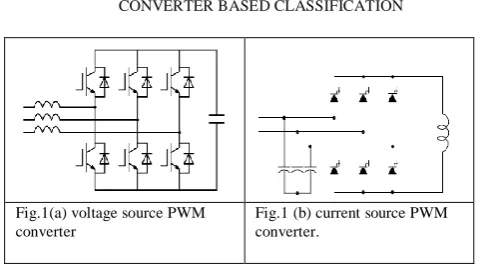
TABLE I
CONVERTER BASED CLASSIFICATION
Fig.1(a) voltage source PWM converter
ISSN: 2231-5381
http://www.ijettjournal.org
Page 110 Both converter in Fig. 1(a) and Fig.1 (b) are similar to thepower circuits used for ac motor drives. They are, however, different in their behaviour because active filters act as non-sinusoidal current or voltage sources. As compared to current-source (CS) PWM converter the voltage-source is more preferred because the voltage source (VS) PWM converter has higher efficiency, cost is lower and smaller in physical size particularly in terms of comparison between the dc capacitor and the dc inductor.
Moreover, the IGBT module that is now available from the market is more suitable for the voltage-source PWM converter because a free-wheeling diode is connected in anti-parallel with each IGBT. This means that in IGBT capability of reverse blocking does not need to provide the in itself, thus bringing more flexibility to device design in a compromise among conducting and switching losses and short-circuit capability than the reverse-blocking IGBT. On the other hand, the current-source PWM converter requires either series connection of a traditional IGBT and a reverse-blocking diode, or the reverse-reverse-blocking IGBT that leads to more complicated device design and fabrication, and slightly worse device characteristics than the traditional IGBT without reverse-blocking capability. The authors of [14] describe shunt active filters using a voltage-source PWM converter and a current-source PWM converter with focus on their comparisons from various points of view.
2.2 Circuit configuration Based classification
1) Shunt APF 2) Series APF
3) Unified power quality conditioner: Series APF+ Shunt APF
4) Hybrid APF: Shunt or Series APF + Passive filter.
2.2.1 Shunt active power filters
The conventional shunt active power filter can perform the harmonic current suppression, reactive power compensation and balancing three-phase currents. Fig. 2 shows a system configuration for filtering of harmonic-current of a non- linear load using a single-phase or three-phase shunt active filter. The standard shunt APF circuit models with IGBT inverter and on the AC side a series inductor. This filter consists of a voltage-source power converter and a filter inductor connected in series. The role of the filter inductor is used to suppress the high frequency ripple current generated while switching the power electronic devices of the power converter. The active filter operate stably and properly by use of inductor .The APF aims to inject this current error at the point of common coupling in order to match the source current as closely as possible with the reference current. This Active power filter with or without a transformer is connected in parallel with the harmonic-producing load. Fig. 3 represents equivalent circuit of Shunt active power Filter.
Fig.2 Shunt Active power filter
Fig.3 Equivalent circuit of Shunt APF
Where ZS= Source impedance
ILH= Is the equivalent harmonic current source ZL= Equivalent load impedance
The shunt active power equations include:
(1)
G= equivalent transfer function of the active filter
(2)
(3)
If (4)
L GI C
I
G 1
L Z
S Z
S V
LH I
G 1
L Z
S Z
L Z
S I
G L Z S Z
S V G LH I
G L Z S Z
G L Z
L I
1 1
1
1 1
h S Z h G L Z
ISSN: 2231-5381
http://www.ijettjournal.org
Page 111 Then the above equations becomes(5)
(6)
(7)
Equation (4) is the required condition for the parallel A.F. to cancel the load harmonic current. We can only predesign G while ZS and ZL are determined by the system.
For harmonic source of pure current source type and equations (2) and (4) consequently become
(8)
(9)
Equation (8) shows that the compensation characteristics of the A.F. are not influenced by ZS (source impedance). This is a major advantage of the A.F. with respect to the passive ones. From Fig.4 the value of C and LF can be determined based on following considerations.
1) The DC bus nominal voltage, Vdc, must be greater than or equal to line voltage peak in order to actively control Ic.
2) The selection of the interface inductance of the active filter is based on the compromise of keeping the output current ripple of the inverter low and the same time to be able to track the desired source current.
3) The required capacitor value is dictated by the maximum acceptable voltage ripple.
Fig.4 Shunt active filter connected to Distribution line
A good initial guess of C is:
C ≥ max ∫ iC dt /ΔvCmax (10) Also,
LF ≥ (0.66 VdC - VΦn)/ max (d iΦL/dt) (11)
Where
VΦn= peak line-neutral voltage
VdC = DC voltage of the DC bus of the inverter iΦL= Line phase current
V
c
max = maximum acceptable voltage ripple,iC = Phase current of the inverter
Advantages of Shunt APF:
1) Low implementation cost.
2) Do not create displacement power factor problems and utility loading.
3) Supply inductance LS, does not affect the harmonic compensation of parallel active filter system. 4) Simple control circuit.
5) Can damp harmonic propagation in a distribution feeder or between two distribution feeders. 6) Easy to connect in parallel a number of active filter
modules in order to achieve higher power requirements.
7) Easy protection and inexpensive isolation switchgear.
8) Easy to be installed.
9) Provides immunity from ambient harmonic loads.
2.2.2 Series active power filters
Using three-phase transformer or three single-phase transformers the series active filter is connected in series with the utility supply voltage. By inserting a series A.F. between the AC supply source and the load where the harmonic source is existing we can force the source current to become almost sinusoidal. This approach is based on a principle of harmonic isolation by controlling the output voltage of the series active filter.Fig.5 shows a system configuration for filtering of harmonic-voltage of a non- linear load using a single-phase or three-phase series active filter.
Fig.5 Series active power filter
Fig.6 Equivalent circuit of Series APF
The series active filter provide high impedance path to harmonic current and thus consequently suppress harmonic current flow from the load to the source.
Lh I C I
1
1 0
L Z
Sh V G LHh I G Sh I
L Z
Sh V LHh I Lh
I
S Z L Z
GLH I
S I
1
1
1
ISSN: 2231-5381
http://www.ijettjournal.org
Page 112 VC=Output Voltage of AF =KGIS (12)(13)
Where G = Equivalent transfer function of the detection circuit of harmonic current, including time
delay of the control circuit. K = gain in pu ohms
If and
Then
Advantages of Series APF:
1) The major advantages of the series active filter over the parallel active power filter are that it can maintain the output voltage waveform to be sinusoidal and balance the three-phase voltages. 2.2.3 Unified power quality conditioner
It consists of shunt active filter and series active filter then combine both with dc link capacitor. The dc link capacitor reduces dc ripple current. It’s another name is “Universal APF”. The main function of UPQC can be summarised as
1) Eliminate voltage and current harmonics 2) Damp out harmonic propagation
3) Load voltage regulation and current balancing 4) Large cost and control complexity
Fig. 7 Unified power-quality conditioner (UPQC)
2.2.4 Hybrid Active Power Filter
The combination of Series and Parallel Active Filters (UPQC) is very complex in control which constitutes high cost. One method to overcome this problem is to replace the Shunt Active Filter with Shunt Passive Filter as passive filters are very simple to implement and don’t require any control circuit. So, the solution turns to be very economical. The hybrid active-passive filters is another type of active filter configuration. It consists of active and passive filter in order to improve performance. In this technique Passive Filter (PF) is tuned to compensate 3rd and 5th order
harmonics and Active Power Filter (APF) compensates all remaining harmonic components which are not compensated by passive filter. The combination of Shunt Active and Shunt Passive Filter is more commercialized and more commonly used. The Series Active Filter with Shunt Passive Filter is usually used in testing field. There are various hybrid APFs reported in literature [13], [15], [16].
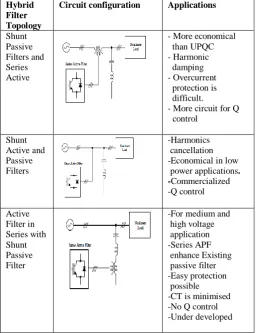
TABLE 2
HYBRID FILTER TOPOLOGY
Hybrid Filter Topology
Circuit configuration Applications
Shunt Passive Filters and Series Active
- More economical than UPQC - Harmonic damping - Overcurrent protection is difficult.
- More circuit for Q control
Shunt Active and Passive Filters
-Harmonics cancellation -Economical in low power applications. -Commercialized -Q control
Active Filter in Series with Shunt Passive Filter
-For medium and high voltage application -Series APF enhance Existing passive filter -Easy protection possible -CT is minimised -No Q control -Under developed
2.3 Supply System Based Classification
1) Two-wire APF 2) Three wire APF 3) Four-wire APF
TABLE 3
SUPPLY SYSTEM BASED CLASSIFICATION
Classification Characteristics
Two-wire APF Used for Single phase nonlinear loads such as domestic appliances. They are of small rating.
Three wire APF Used for three phase nonlinear load without neutral such as Adjustable Speed Drive (ASD).
KG L Z S Z
S V
KG L Z S Z
L I L Z
S I
h L Z K
h L Z S Z
K
Sh V Lh I L Z C
V
0
ISSN: 2231-5381
http://www.ijettjournal.org
Page 113Four-wire APF Applicable to Single phase nonlinear loads fed from four wire supply system, such as computers, commercial lighting .It eliminate excessive neutral current and unbalance.
2.4 Classification Based on Power Rating and Speed of Response
The size of non-linear loads plays a major in making decisions to implement the control strategies of the active filters. The filter required for compensation must be practical for the load and this affects the speed of response.
2.4.1 Low Power Applications
APFs of this category have power ratings below 100kVA. These APFs usually employed in residential areas, commercial buildings hospitals and for medium sized factory loads, and for motor drives systems. APFs for this power range use sophisticated techniques with number of PWM pulses and voltage or current source inverters .The response time for smaller application is relatively much faster than high power range and is in the range of microsecond to ten milliseconds.
2.4.2 Medium Power Applications
The power systems having power rating in the range of 100kVA-10MVA fall into the category of medium power. The major objective is the elimination of current harmonics as the impact of phase unbalance is less. The speed of response of this range of application is the order of tens of milliseconds.
2.4.3 High Power Applications
The power systems having power rating above 10MVA fall into the category of high power applications. The required response time for this case is in the range of tens of seconds, which is sufficient for contactors and circuit breakers to operate after taking the optimal-switching decision. Power fluctuations in the range of a few seconds are, on the other hand, treated by the generating stations' ancillary devices.
III. SELECTION OF AF'S FOR SPECIFIC APPLICATION CONSIDERATIONS
With the availability of various APF the selection of the AF for a particular application is an important task for end users and application engineers. There are widely varying application requirements, such as single-phase or three-phase, three-wire and four wire systems, requiring current- or voltage-based compensation. Moreover, there are a number of AF configurations which may cater to the needs of individual users. A brief list of criteria for selection of an appropriate AF for a specific application is discussed in this section. Table 5 shows a brief summary of selection of suitable AF's for specific users.
Let us take various configurations for active filter
A. Active Series B. Active Shunt C. UPQC
D. Hybrid of Active Series and Passive Shunt E. Hybrid of Active Shunt and Active Series
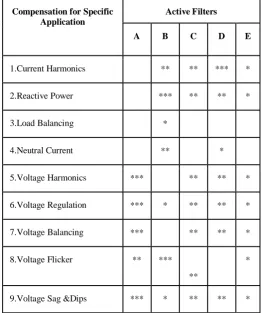
TABLE 4
TABLE GIVE SELECTION OF AF'S FOR SPECIFIC APPLICATIONS
Compensation for Specific Application
Active Filters
A B C D E
1.Current Harmonics ** ** *** *
2.Reactive Power *** ** ** *
3.Load Balancing *
4.Neutral Current ** *
5.Voltage Harmonics *** ** ** *
6.Voltage Regulation *** * ** ** *
7.Voltage Balancing *** ** ** *
8.Voltage Flicker ** ***
**
*
9.Voltage Sag &Dips *** * ** ** *
AF Configuration with higher number of * is more preferred
IV.
C
ONCLUSIONAn extensive review of AF's has been presented in this paper to provide a clear perspective on various aspects of the AF. On the basis of various configuration of APF one can select the active power filter for particular application for compensation of parameters as listed in Table 4. It is hoped that the discussion and classification of AF’s presented in this paper will provide some useful information to help make the selection of an appropriate harmonic reduction method for a given application on an easier task.
V. REFERENCES
[1] R. D. Henderson and P. J. Rose, “Harmonics: The effects on power quality and transformers,” IEEE Trans. Industrial Applications, pp.528– 532, 1994.
[2] C. J. Wu, J. C. Chiang, S. S. Yen, C. J. Liao, J. S. Yang, and T. Y. Guo, “Investigation and mitigation of harmonic amplification problems caused by single-tuned filters,” IEEE Trans. Power Del., pp. 800–806,1998.
ISSN: 2231-5381
http://www.ijettjournal.org
Page 114pp.1312-1322, Nov /Dec.1995.
[4] Bhim Singh, Kamal Al-Haddad, Ambrish Chandra, “A review of active filters for power quality improvement”. IEEE Trans on I.E. Vol.46, No.5, pp.960-971. October, 1999.
[5] S. Buso, L. Malesani, and P. Mattavelli, “Comparison of current control techniques for active filters applications”. IEEE Trans. Ind.Electron, vol. 45, pp. 722–729, Oct. 1998
[6] Roger C.Dugan, Mark F.McGranaghan and H.Wayne Beaty “Electrical Power Systems Quality”, 2nd ed., New York McGraw-Hill, 1996, pp. 1-260.
[7] Hurng-Liahng ,Jou,Jinn-Chang Wu, Yao-Jen Chang, and Ya-Tsung Feng,”A Novel Active Power Filter for Harmonic Suppression” IEEE Transactions on Power Delivery, Vol. 20, No. 2, April 2005.
[8] A. Abellan, J. M. Benavent, and G. Garcera, “A new control method for obtaining reference currents of shunt active power filters in unbalanced and nonsinusoidal conditions,” IEEE ISIE’99, pp. 831–836, 1999.
[9] S. Bhattacharya, P. T. Cheng, and D. M. Divan, “Hybrid solutions for improving passive filter performance in high power applications,” IEEE Trans. Ind. Appl., pp. 732–747, 1997.
[10] H. Fujita and H. Akagi, “Apractical approach to harmonic compensation in power system, series connection of passive and active filters,” IEEE Trans. Ind. Appl., pp. 1020–1025, 1991.
[11] J. Dixon, J. Espinoza, L. Moran, and D. Rivas, “A simple control scheme for hybrid active power filter,” in IEEE PESC, 2000, pp. 991–996.
[12] M. Rastogi, N. Mohan, and A. A. Edris, “Hybrid-active filtering of harmonic currents in power systems,” IEEE Trans. Power Del., vol. 10, no.4, pp. 1994–2000, Oct. 1995.
[13]M. El-Habrouk, M. K. Darwish and P. Mehta, “ActivePower Filters: A Review” Proc. IEE Electric Power Applications, vol. 147, no. 5, pp.
403-413, 2000.
[14] M. Routimo, M. Salo, and H. Tuusa, “Comparison of voltage source and current-source shunt active power filters”, Conf. Rec. IEEE Power Electronics Specialists Conference (PESC), pp.2571–2577 (2005).
[15]L. Chen and A. Jouanne, “A Comparison and Assess-ment of Hybrid Filter Topologies and Control Algorithms” Proceedings of the IEEE Power Electronics Specialists Conference (PESC), Vancouver, Canada, 2001, pp. 565-570.