http://www.sciencepublishinggroup.com/j/ijssn doi: 10.11648/j.ijssn.20170504.12
ISSN: 2329-1796 (Print); ISSN: 2329-1788 (Online)
Gsm Based Low Cost Smart Irrigation System with
Wireless Valve Control
Saravanan Ragavan
1, Ramesh Thangavel
21Departmentof Electrical and Electronics Engineering, Tirumala Engineering College, Hyderabad, India
2
Departmentof Electrical and Electronics Engineering, Karpagam Academy of Higher Education, Coimbatore, India
Email address:
[email protected] (S. Ragavan), [email protected] (R. Thangavel)
To cite this article:
Saravanan Ragavan, Ramesh Thangavel. Gsm Based Low Cost Smart Irrigation System with Wireless Valve Control. International Journal of Sensors and Sensor Networks. Vol. 5, No. 4, 2017, pp. 54-62. doi: 10.11648/j.ijssn.20170504.12
Received: October 23, 2017; Accepted: November 9, 2017; Published: December 22, 2017
Abstract:
In this paper presents to optimize the cost of the irrigation system and water consumption for agricultural crop based on a wireless network, that are Internet of Things (IoT) radio communications. The system consists of smart mobile phone for surveillance, the motor controller unit and the field controller unit. The SIM 900 GSM module is available in motor controller unit (PIC16F877A). Information from the field controller unit such as soil moisture, land humidity, temperature is sent to the motor controller unit through Radio & Communication. From motor controller unit the information is sent to the registered mobile number through GSM module. A Command can be sent from the mobile by GSM message to control the valves and motor.Keywords:
Irrigation, GSM, Valve Control, Soil Sensor1. Introduction
Farmers are the backbone of our country. The farmers should be given first priority in all aspects. India is a country where most of the people are dependent on agricultural activities. Cultivation and farming are considered as the back bone of the country. Irrigation plays an important role in agriculture. Farmers are facing many problems during irrigation process. In many of the states in India, electrical power is not provided properly to the farmers for their irrigation purpose. Due to this, frequent interruption of power, low voltage profile and water shortage. To avoid the above such problems, the smart irrigation system will play a vital for the irrigation purpose. Here, Internet of Things based low cost, smart irrigation system will be proposed in this project. To Experiment the possibilities of this project is to on /off the AC motor through smart mobile phone. This project is very useful to control the AC motor used in the application through wireless communication. By controlling the AC motor from anywhere in the captured area. ZIGBEE based wireless valve control is also used. The objectives of this paper were to control the water motor automatically and select the direction of the flow of water in pipe with the help
of soil moisture sensor. Finally, send the information (operation of the motor and direction of water) of the farm field to the mobile message and g-mail account of the user.
2. Control Strategies
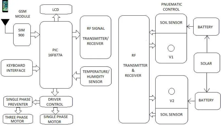
The main block diagram consists of the Mobile communication, GSM interface circuit, Solenoid control valve, LCD display, Radio frequency interface, Power supply, Keyboard interface, Single phase preventer, Driver circuit, Temperature and humidity sensor and Soil sensor.
2.1. Mobile Communication
long-range control just because of the low cost and well real-time.
Figure 1. Block diagram.
A GSM modem is a wireless modem that works with a GSM wireless network. A wireless modem behaves like a dial-up modem. The main difference between them is that a dial-up modem sends and receives data through a fixed telephone line while a wireless modem sends and receives data through radio waves.
A GSM modem can be an external device or a PC Card/PCMCIA Card. Typically, an external GSM modem is connected to a computer through a serial cable or a USB cable. A GSM modem in the form of a PC Card / PCMCIA Card is designed for use with a laptop computer. It should be inserted into one of the PC Card / PCMCIA Card slots of a laptop computer. Like a GSM mobile phone, a GSM modem requires a SIM card from a wireless carrier in order to operate.
As mentioned in earlier sections of this SMS tutorial, computers use AT commands to control modems. Both GSM modems and dial-up modems support a common set of standard AT commands. You can use a GSM modem just like a dial-up modem.
In addition to the standard AT commands, GSM modems support an extended set of AT commands. These extended AT commands are defined in the GSM standards. With the extended AT commands, you can do things like:
1. Reading, writing and deleting SMS messages. 2. Sending SMS messages.
3. Monitoring the signal strength.
4. Monitoring the charging status and charge level of the battery.
5. Reading, writing and searching phone book entries. The number of SMS messages that can be processed by a GSM modem per minute is very low -- only about six to ten SMS messages per minute.
In this system, the GSM 300/1800 MHz network double band module made in Simcom Company is selected as GSM
module. This module is capable to analyze band rate automatically and improve the performance of electronic public service. This module with energy save function, embedded TCP/IP and transparent mode belongs to the series of GPRS in three frequencies (900/1800/1900). The peripheral circuit of SIM300DZ mainly consists of the communication interfaces of SIM cassette and module, such as SIM-CLK and SIM I/O, which are the communication wires of module clock and data, SIM-RST and VCC, which are the reset and the power supply. What’s more, the RXD and TXD are included in the peripheral circuit of SIM300DZ which connect with the serial port the MCU. It is the AT instructions that conveyed between the MCU and GSM through the very two channels. In addition the GSM module includes voice system channel and MIC channel. These channels are switched by MCU because of the AT instructions which are mainly applied to the switching between the voice and microphone in the monitor system. Finally, the transmitting ports IN+ and I are also included which are with the dual tone multi frequency (DTMF) signals. When the user communicates with the phone equipped in the car, if the button is pressed, it will produce a DTMF signal which is sent out to the multi frequency decode chip to analyze and produce Q signal through IN+ and IN-At this moment, the MCU decides how to operate according to the Q signal.
2.2. Solenoid Control Valve
valves may have two or more ports. In the case of a two-port valve the flow is switched on or off; in the case of a three-port valve, the outflow is switched between the two outlet ports. Multiple solenoid valves can be placed together on a manifold Solenoid valves are the most frequently used control elements in fluidics. Their tasks are to shut off, release, dose, distribute or mix fluids. They are found in many application areas. Solenoids offer fast and safe switching, high reliability, long service life, good medium compatibility of the materials used, low control power and compact design. Besides the plunger-type actuator which is used most frequently, pivoted-armature actuators and rocker actuators are also used.
2.3. LCD Display
Liquid crystal displays (LCD’s) have materials, which combine the properties of both liquids and crystals. Rather than having a melting point, they have a temperature range within which the molecules are almost as mobile as they would be in a liquid, but are grouped together in an ordered form similar to a crystal.
An LCD contains of two glass panels, with the liquid crystal material, sand witched in between them. The inner surface of the glass plates is coated with transparent electrodes which define the character, symbols or patterns to be displayed polymeric layers are present in between the electrodes and the liquid crystal, which makes the liquid crystal molecules to maintain a defined orientation angle.
One each polarizes are pasted outside the two glass panels. These polarizes would rotate the light rays passing through them to a definite angle, in a particular direction. When the LCD is in the off state, light rays are rotated by the two polarizes and the liquid crystal, such that the light rays come out of the LCD without any orientation, and hence the LCD appears transparent.
When satisfactory voltage is realistic to the electrodes, the liquid crystal molecules would be aligned in a specific direction. The light rays passing through the LCD would be rotated by the polarizes, which would result in activating / highlighting the desired characters. The LCD’s are lightweight with only a few millimeters thickness. Since the LCD’s consume less power, they are compatible with low power electronic circuits, and can be powered for long durations.
The LCD does not generate light and so light is needed to read the display. By using backlighting, reading is possible in the dark. The LCD’s have long life and a wide operating temperature range. Changing the display size or the layout size is relatively simple which makes the LCD’s more customers friendly.
The LCDs used exclusively in watches, calculators and measuring instruments are the simple seven-segment displays, having a limited amount of numeric data. The recent advances in technology have resulted in better legibility, more information displaying capability and a wider temperature range. These have resulted in the LCDs being
comprehensively used in telecommunications and
entertainment electronics. The LCDs have even started changing the cathode ray tubes (CRTs) used for the display of text and graphics, and also in small TV applications.
Crystalloids dot–matrix (alphanumeric) liquid crystal displays are available in TN, STN types, with or without backlight. The use of C-MOS LCD controller and driver ICs result in low power consumption. These modules can be interfaced with a 4-bit or 8-bit microprocessor /Micro controller. LCDs are used in similar applications where LEDs are used. These applications are displayed of numeric and alphanumeric characters in dot matrix and segment displays.
2.4. RF Transmitter and Receiver
Radio frequency, or RF, is a frequency or rate of oscillation within the range of about 3 Hz and 300 GHz. This range corresponds to frequency of alternating current electrical signals used to produce and detect radio waves. Since most of this range is beyond the vibration rate that most mechanical systems can respond to, RF usually refers to oscillations in electrical circuits.
The Electrical currents that oscillate at RF have special properties not shared by direct current signals. One such property is the ease with which it can ionize air to create a conductive path through the air. This property is exploited by 'high frequency' units used in electric arc welding. Another special property is an electromagnetic force that drives the RF current to the surface of conductors, known as the skin effect. Another property is the ability to appear to flow through paths that contain insulating material, like the dielectric insulator of a capacitor. The degree of the effect of these properties depends on the frequency of the signals.
RF transmitter and receiver are available for operation in the 868-870MHz band in Europe and the 902–928MHz band in North America, both modules combine full screening with internal filtering to ensure EMC compliance by minimizing spurious radiation and susceptibility.
These RF transmitter & receiver will suit one-to-one and multi-node wireless links in such applications as car and building security, EPOS and inventory tracking, remote industrial process monitoring and data networks. Because of their small size and low power requirements, both Modules are ideal for use in portable, battery-powered applications such as handheld terminals.
2.5. Encoder
enhances the application flexibility of the 318 series of encoders. In this circuit the input signal to be encoded is given to AD7-AD0 input pins of the encoder. Here the input signal may be from keyboard, parallel port, microcontroller or any interfacing device. The encoder output address pins are shorted so the output encoded signal is the combination of (A0-A9) address signal and (D0-D7) data signal. The output encoded signal is taken from 8th which is connected to an RF transmitter section.
2.6. RF Transmitter
Whenever a high output pulse is given to the base of the transistor BF 494, the transistor is conducting so tank circuit is oscillating. The tank circuit consists of L2 and C4 generating 35MHz carrier signal. Then the modulated signal is given LC filter section. After the filtration the RF modulated signal is transmitted through an antenna.
2.7. RF Receiver
The RF receiver is used to receive the encoded data which is transmitted by the RF transmitter. Then the received data are given to a transistor, which acts as an amplifier. Then the amplified signal is given to carrier demodulator section in which transistor Q1 is turned on and turn off conducting depends on the signal. Due to this the capacitor C14 is charged and discharged so carrier signal is removed and saw tooth signal is appearing across the capacitor. Then this saw tooth signal is given to the comparator. The comparator circuit is constructed by LM558.
The comparator is used to convert the saw tooth signal to exact square pulse. Then the encoded signal is given to decoder in order to get the decoded original signal.
2.8. Decoder
In this circuit HT648 is used as a decoder. The 318 decoder a series of CMOS LSIs for remote control system application. They are paired with 318 series of encoders. For proper operation a pair of encoder/decoder pair with the same number of address and data format should be selected. The 318 series of decoder receives the serial address and data from that series of encoders that are transmitted by a carrier using an RF or an IR transmission medium. It then compares the serial input data twice continuously with its local address. If no errors or unmatched codes are encountered, the input data codes are decoded and then transferred to the output pins. The VT pin also goes high to indicate a valid transmission.
The 318 decoders are capable of decoding 18 bits of information that consists of N bits of address and 18-N bits of data. To meet various applications they are arranged to provide a number of data pins whose range is from 0 to 8 and an address pin whose range is from 8 to 18. In addition, the 318 decoders provide various combinations of address/ data numbering different package.
In this circuit the received encoded signal is 9th pin of the decoder. Now the decoder separates the address (A0-A9) and data signal (D0-D7). Then the output data signal is given to a
microcontroller or any other interfacing device.
2.9. Power Supply Block
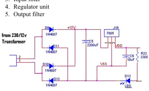
The present chapter introduces the operation of power supply circuits built using filters, rectifiers and then voltage regulators. Starting with an AC voltage, a steady DC voltage is obtained by rectifying the AC voltage, then filtering to a DC level, and finally regulating to obtain a desired fixed DC voltage. The regulation is usually obtained from an IC voltage regulator unit, which remain the same if the input DC voltage varies or the output load connected to DC voltage changes. A block diagram containing the parts of a typical power supply and the voltage at various points in the unit is shown in the Figure 2.
The AC voltage, typically 120 V rms, is connected to a transformer, which steps that AC voltage down to the level for the desired DC output. A diode rectifier that provides a full-wave rectified voltage that is initially filtered by a simple capacitor filter to produce a DC voltage. This resulting DC voltage usually as some ripple or AC voltage variation. A regulated circuit can use this DC inputs to provide a DC voltage that not only has much less ripple voltage but also remains the same DC value even if the input DC voltage varies somewhat, or the load connected to the output DC voltage changes this voltage regulation is usually obtained using one of a number of popular voltage regulation IC unit. The Power supply unit consists of the following units.
1. Step down transformer 2. Rectifier unit
3. Input filter 4. Regulator unit 5. Output filter
Figure 2. Power supply circuit diagram.
2.10. Three-Terminal Voltage Regulator
Figure 3. Three terminal voltage regulator.
2.11. Keyboard Interface
The keyboard which is used in project to register the mobile number for sending the motor, valve open and close condition and soil dry and wet condition information via GSM module.
2.12. Single Phase Preventer
Protection of induction motors against single phasing or reverse phase or unbalance supply is one of the major problems in electrical systems. For safe running of 3-phase motors, special protections that keep a continuous watch on supply conditions are very essentials. The major cause of maximum motors burn-out is overloading which occurs due
to unbalance supply or single phasing. Phase failure occurs in case of fuse blown-off, loose connections or loss of phase from the supply itself.
2.13. Driver Circuit
Driver circuits are most commonly used to amplify signals from controllers or microcontrollers in order to control power switches in semiconductor devices. Driver circuits often take on additional functions which include isolating the control circuit and the power circuit, detecting malfunctions, storing and reporting failures in the control system, serving as a precaution against failure, analyzing sensor signals, and creating auxiliary voltages.
Figure 4. Bock diagram of driver circuit.
2.14. Temperature and Humidity Sensor
A humidity sensor (or hygrometer) senses, measures and
moisture that can be held at that air temperature. The warmer the air temperature is, the more moisture it can hold. Humidity / dew sensors use capacitive measurement, which relies on electrical capacitance. Electrical capacity is the ability of two nearby electrical conductors to create an electrical field between them. The sensor is composed of two
metal plates and contains a non-conductive polymer film between them. This film collects moisture from the air, which causes the voltage between the two plates to change. These voltage changes are converted into digital readings showing the level of moisture in the air.
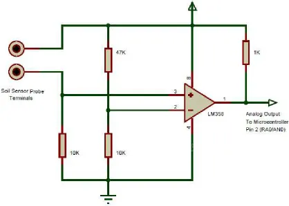
2.15. Soil Sensor
Figure 5. Circuit diagram of soil sensor.
The use of sensors can afford quantitative information to help guide and automate the decision-making process for irrigation. Such sensors include those that are generally used for weather stations as well as sensors to monitor the water status of the soil or substrate, and sensors that can be used to monitor and troubleshoot irrigation systems. Although collecting data with sensors is relatively easy, data are only useful if the sensors are used correctly and the limitations of sensors are understood. Optimizing the value of the collected data requires selecting the best sensor (s) for a particular purpose, determining the optimal number of sensors to be deployed, and assuring that collected data are as accurate and precise as possible. We designate general sensing principles and how these principles can be applied to a variety of sensors. Based on our experience, proper use of sensors can result in large increases in irrigation efficiency and improve the profitability of ornamental production in greenhouses and nurseries.
3. Simulation Circuit Diagram
Figure 6. Simulation diagram.
4. Hardware Circuit Diagram
4.1. Block Diagram-Well Side
Figure 8. Block diagram of well side.
4.2. Block Diagram-Land Side
Figure 9. Block diagram of land side.
The AC voltage 220V is connected to a transformer, which steps that AC voltage down to the level of the 5V desired AC output. A rectifier provides a full-wave rectified voltage that is initially filtered by a simple capacitor filter to produce a DC voltage. This resulting DC voltage, usually has some ripple or AC voltage variation. A regulator circuit removes the ripples and also remains the same DC value even if the input DC voltage varies, or the load connected to the output DC voltage changes.
In this project PIC16f877a is used as a main unit, which is used to process the signal that comes from GSM modem and all peripherals. The PIC microcontroller is used in this
project to identify the phone call which is coming through the GSM modem. In that time the PIC microcontroller reduces the speed of the motor and inform the user that the arrival of a call by using an LCD. The 16x2 LCD is used as a display unit which is used for alerting the user, two PORTS are allocated for LCD connections.
The regulated 5V supply is connected to the GSM modem and all peripherals. IC MAX232 is used to communicate between the PIC microcontroller and the GSM modem. The LCD16x2 is used as a display unit which is used for alerting the user, two PORTS are allocated for LCD connections. The soil sensor will sense the land condition, whether the land is wet or dry. And send the information through SMS to the registered mobile number via GSM module. After this information is received, the motor and the valves are controlled by sending SMS to the GSM circuit. If the land is dry condition, first the corresponding valve gets opened the motor is turned ON by the control of registered number. During the running period, the land changed from dry condition to wet condition the motor is automatically turned OFF and the valve gets closed.
When the power supply is given to the circuit, the display will show the title of the project. After the power supply is turned ON, the display shows that to enter the mobile number for receiving information from the field side. The display shows the registered mobile number. After the mobile are registered, the display will shows whether the mobile number is stored or not.
to the command. The SMS are send to the GSM module, if it received it shows in the display. The wrong command are send to the GSM module, the display shows that as invalid format. The command is correct to turn ON the motor, it will be displayed in display unit.
Figure 10. Hardware model.
5. Conclusion
IoT is brought forwards to use in automatic irrigation. Thus the project of the irrigation system and water consumption for agricultural crop based on wireless network that are IoT and radio communications. The photovoltaic power supply to the field unit. Any cell phone can send command to the controllers or collect information from the controller. Only during day time a valves can be controlled because of solar photovoltaic. GSM and radio frequency provides credible communication for the device.
References
[1] Joaquín Gutiérrez, Juan Francisco Villa-Medina, Alejandra Nieto-Garibay, Miguel Ángel Porta-Gándara, Automated Irrigation System Using a Wireless Sensor Network and GPRS Module, IEEE Transactions on Instrumentation and Measurement, Vol. 63, No. 1, pp. 166-176, 2013.
[2] Xiaohong Peng, Guodong Liu, Intelligent Water-Saving Irrigation System Based on Fuzzy Control and Wireless Sensor Network”, InProceedings of International Conference on Digital Home, pp 252-256, 2012.
[3] Vandana Dubey, Nilesh Dubey, Shailesh Singh Chouhan, Wireless Sensor Network based Remote Irrigation Control System and Automation using DTMF code, In Proceedings of International Conference on Communication Systems and Network Technologies, pp. 34-37, 2011.
[4] Rajeev G. Vishwakarma, Vijay Choudhary, Wireless Solution for Irrigation in Agriculture, In proceedings of International Conference onSignal Processing, Communication, Computing and NetworkingTechnologies, pp. 61-63, 2011.
[5] Liang Zhao, Liyuan He, Xing Jin, Wenjun Yu, Design of Wireless Sensor Network Middleware for Agricultural Applications, Daoliang Li, Yingyi Chen eds. Computer and Computing Technologies in Agriculture IV, Springer Berlin Heidelberg, pp 270-279, 2012.
[6] Shaikh, Bhawani Shankar Chowdhry, Habib M. Ammari,
Muhammad Aslam Uqaili, Assadullah Shah eds. Wireless Sensor Networks for Developing Countries, Springer Berlin Heidelberg, pp. 1-13, 2013.
[7] Sathish Kannan K., Thilagavathi G., Online Farming Based on Embedded Systems and Wireless Sensor Networks, In Proceedings of International Conference on Computation of Power, Energy, Information and Communication, pp. 71-74, 2013.
[8] Divya P., Surbhi Sonkiya, Preeti Das, Manjusha V. V, Maneesha V. Ramesh, Context Aware Wireless Irrigation System”, In Proceedings of International Conference on Computer,Communications, and Control Technology (I4CT), pp 310-314, 2014.
[9] Baviskar, J. J., Mulla, A. Y., Baviskar, A. J., Dsouza, K., Khan M., Designing of Mobile Controlled Automatic Interactive Voice Response Irrigation System”, In Proceedings of International Conference onRecent Advances and Innovations in Engineering, pp. 1-6, 2014.
[10] Shuang-Ming Yu, Peng Feng, Nan-Jian Wu, Passive and Semi-Passive Wireless Temperature and Humidity Sensors Based on EPC Generation-2 UHF Protocol, IEEE Sensors Journal, Vol. 15, No. 4, pp. 2403-2411, 2014.
[11] Rana Biswas romit beed ankita bhaumik shamik chakrabarty raghav toshniwal, International Journal of Advanced Engineering and Global Technology, vol. 03 no. 01 January 2015.
[12] Er. Faruk Poyen Balaka Dutta Swarup Manna Arkeya Pal Apurba K Ghosh Rajib Bandhopadhyay, International conference on Innovative Engineering Technologies (ICIET 2014) pp. 28-29 2014.
[13] Hemant Ingale N. N. K Asatingale Sipana's, International Journal of Advanced Research in Computer Science and Software Engineering, vol. 2 no. 11 November 2012.
[14] M Karthikeswari P Mithradevi, International Journal of Advanced Research in Electrical Electronics and Instrumentation Engineering (An ISO 3297, 2007 Certified Organization), vol. 3 no. 12 December 2014.
[15] Basil M. Hamed Mohammed S. El-Moghany "I. J. Intelligent Systems and Applications" vol. 1 pp. 46-52 2012.
[16] Joaquin Gutierrez Juan Francisco Villa-Medina Alejandra Nieto Garibay Miguel Angel Porta-Gandara "Automated Irrigation System Using a Wireless Sensor Network and GPRS Module" 2013.
[17] Jia Uddin S. M. Taslim Reza Qader Newaz Jamal Uddin Touhidul Islam Jong-Myon Kim "Automated Irrigation System Using Solar Power" IEEE 2012.
[18] Sweta S. Patil A. V. Malvijay "Review for ARM based agriculture field monitoring system" International Journal of Scientific and Research Publications vol. 4 no. 2 February 2014.
[19] Rafael Munoz-Carpena Herbert Bryan Waldemar Klassen, Automatic soil moisture based drip irrigation for improving tomato production, Proc. Fla. State. Hort. Soc. vol. 116 pp. 80-85 2003.