Published online October 07, 2014 (http://www.sciencepublishinggroup.com/j/ajae) doi: 10.11648/j.ajae.s.2015020101.12
Hands-on engineering education by construction and
testing of models of sailing boats
Ahmed Farouk Abdel Gawad
Professor of Computational Fluid Mechanics, Mech. Eng. Dept., Umm Al-Qura Univ., Makkah, Saudi Arabia
Email address:
To cite this article:
Ahmed Farouk Abdel Gawad. Hands-On Engineering Education by Construction and Testing of Models of Sailing Boats. American Journal of Aerospace Engineering. Special Issue: Hands-on Learning Technique for Multidisciplinary Engineering Education.
Vol. 2, No. 1-1, 2015, pp. 11-30. doi: 10.11648/j.ajae.s.2015020101.12
Abstract:
This paper introduces involvement of the hands-on learning method. According to the modern environment of technology, engineering students have to realize the multidisciplinary nature of engineering systems. This learning technique is essential to offer students the necessary skills to master practical, organizational and work-group cleverness. The work is concerned with the redesign, construction and operation of two models of sailing boats. The approach of the work and final outputs are illustrated.Keywords:
Hands-On Learning, Multidisciplinary Engineering, Sailing Boats, Laboratory Investigations1. Present Project
The scheme of hands-on learning technique is established in this work though supervising B.Sc. graduation project. Students had to redesign, construct and test a sailing boat model. Sailing boats represent a very rich multidisciplinary teaching field. Investigation of sailing boats covers the areas of sail aerodynamics, boat hydrodynamics, control systems, boat stability, material choice, manufacturing techniques, design aspects, etc. Also, this type of projects increases the knowledge of students about marine activities and the different types of sailing boats.
The students were divided into two groups. The first group (four students) concerned the case of a mono-hull sailing boat. This type of boats is the widely known and used allover the world. The other group (six students) concerned a multi-hull (catamaran) boat. This type of boats has many advantages and practical applications.
The technique of dividing the students into two groups has some objectives, namely: (i) Inspiring competition between the two groups for better achievement. (ii) Motivating the cooperation between the two groups in the common issues of the work. Thus, students learn how to organize activities between working groups in the same field. (iii) Increasing the knowledge and experience about different types of sailing boats instead of concentration on one type only. (iv) Reducing the overall effort and time-needs of every student by relatively increasing the students' number.
2. Background
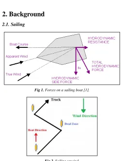
2.1. Sailing
Fig 1. Forces on a sailing boat [1].
Sailing is the skillful art of controlling the motion of a sailing ship or smaller boat, across a body of water. A boat moves as wind pushes on its sails. This is obvious when the boat is sailing downwind. The keel of a boat keeps it from strafing to the sides. This allows a boat to sail downwind but at an angle.
The force of the wind is used to create motion by using one or more sails, Fig. 1.
When sailing downwind (away from the wind source) the vessel's motion is derived from the simple force of the wind pushing the sail. When sailing upwind (towards the wind
source), the movement of air over the sails acts in the same way as air moving over an aircraft's wing. Air flowing over the sail generates lift. This pulls the sail (and the boat) ahead, but also pushes it downwind rather strongly. A basic rule of sailing is that it is not possible to sail directly into the wind. Generally speaking, a boat can sail 45 degrees off the wind, Fig. 2. Since a boat cannot sail directly into the wind, but the destination is often upwind, one can only get there by sailing close-hauled with the wind coming.
2.2. Balance of Hull and Sails
Fig 3. Balance of hull and sails [2].
Due to the pressure of the wind in the sails, a sailboat side-slips a little as it goes forward. This is called "making leeway." Since the water has to travel a greater distance on the windward side of the keel, an area of reduced pressure produces "lift" to windward. The more lift from the underwater surfaces, the less leeway the boat makes, Fig. 3.
Fig 4. Center of forces (CE) and center of lateral resistance (CLR) [3].
The CE of the boat is the "Center" of all the forces acting to push the boat sideways against the center of all the forces resisting that push. The CLR is the "Center of Lateral Resistance" of the hull shape, Fig. 4.
3. Types of Boats
The boats can be classified according to rigs, meaning the way they set their sails, as in the following sections.
3.1. Single Rigs
3.1.1. Sloop
Fig 5a. Sloop boat [4].
3.1.2. Catboat
A catboat has one mast and one sail, with the mast usually stepped forward. Since there is no second sail on a catboat, it is a good choice for sailing shorthanded or with children. Cruising catboats have cabins and normally range in overall length from 5-10 meters. Others are fully or partially decked and suitable for day sailing or camp cruising [5], Fig. 5b.
Fig 5b. Catboats [5].
3.1.3. Sunfish (Lateen Rig)
Fig 5c. Sunfish (lateen rig) boat [6].
The Sunfish sailboat is a personal size, beach launched sailing dinghy utilizing a pontoon type hull carrying a lateen sail mounted to an un-stayed mast. Having a lateen sail with its simple two line rigging makes a Sunfish simple to learn sailing on and to set up. Upgrades can be added to enhance sail control for competitive sailing, making the boat attractive
to novice and experienced sailors [6], Fig. 5c.
3.1.4. Catamaran
A catamaran is a multi-hulled vessel consisting of two parallel hulls of equal size. A catamaran is geometry-stabilized, that is, it derives its stability from its wide beam, rather than having a ballasted keel like a mono-hull. Being ballast-free and lighter than a mono-hull, a catamaran can have a very shallow draught. The two hulls are much finer than a mono-hull's, the reduced drag allowing faster speeds. A sailing multi-hull heels much less than a sailing mono-hull, so its sails spill less wind and are more efficient. The limited heeling means the ride may be more comfortable for passengers and crew although catamarans can exhibit an unsettling "hobby-horse" motion. A catamaran's two hulls are joined by some structure, the most basic being a frame. More sophisticated catamarans combine accommodation into the bridging superstructure [7], Fig. 5d.
Fig 5d. Catamaran boat [7].
Fig 5. Single-rig boats.
3.2. Divided Rigs
3.2.1. Schooner
Fig 6a. Schooner boat [8].
the rear mast(s). Such vessels were first used by the Dutch in the 16th or 17th century. The most common type of schooners, with two-masts, were popular in trades that required speed and windward ability, such as slaving, blockade running, and fishing. Schooners were popular on both sides of the Atlantic in the late nineteenth and early twentieth centuries [8], Fig. 6a.
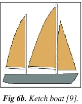
3.2.2. Ketch
Fig 6b. Ketch boat [9].
A ketch is a sailing craft with two masts, both rigged fore-and-aft: a mainmast and a shorter mizzen mast abaft the mainmast but forward of the rudder post. To assist going to windward, a ketch may carry one or more jibs or foresails. If a ketch has no jibs, it is called a cat ketch. The large fore-and-aft sail on the mainmast is the mainsail, while the sail on the mizzen mast is the mizzen. These sails may be any type of fore-and-aft sail, in any combination. Most modern ketches are Bermuda rigged, but other possible rigs on a ketch include gunter rigs and gaff rigs [9], Fig. 6b.
3.2.3. Yawl
A yawl is a two-mast sailing craft similar to a sloop or cutter but with an additional mast (mizzenmast or mizzen mast) located well aft of the main mast, often right on the transom, specifically aft of the rudder post. The yawl was
originally developed as a rig for commercial fishing boats. In the 1950s and 60s, yawls were developed for ocean racing, to take advantage of the handicapping rule that did not penalize them for flying a mizzen staysail, which on long ocean races, often downwind, were a great advantage [10], Fig. 6c.
Fig 6c. Ketch boat [10].
Fig 6. Divided-rigs boats.
4. Present First Model (Mono-Hull Boat)
4.1. Description of the Boat Model
Fig 7. Overall shape and dimensions of the boat prototype [11].
The layout of the prototype is shown in Fig. 8.
Table 1. List of the layout items of Fig. 8, [11].
Item No. Description Item No. Description Item No. Description
1 Forepeak 12 Outboard 23 mooring
2 Berth 13 Outboard 24 mainsheet
3 Settee 14 Cockpit 25 Jib
4 Galley 15 Mast 26 outboard
5 Pillar 16 Cabin 27 Chainplate
6 Table 17 Steering 28 flotation
7 Floorboard 18 Bow 29 Inner
8 Centreboard 19 Pulpit 30 Shelf
9 Centreboard 20 Winch 31 Stove
10 Centreboard 21 Cleat 32 locker
11 Step 22 Toe
The items that appear in Fig. 8 are listed in Table 1. The construction details and dimensions of the model are shown
Table 2. List of the layout items of Fig. 9, [11].
Item No. Description
1 bow transom (A), plywood, =10 mm
2 beam, pine, 30×60 mm
3 frame, pine, 30×60 mm
4 stringer, pine laminate, 25×40 mm
5 sheer clamp, oak, 25×60 mm
6 forefoot, oak laminate, =40 mm
7 bow transom knee, oak, =30 mm
8 bulkhead (B), plywood, =10 mm
9 plank, pine, 20×30 mm
10 berth plating, plywood, =8 mm
11 Floor timber, pine, 30×100 mm
12 knee (both sides), plywood, =6 mm
13 keel, oak laminate, =30 mm
14 carling, pine, 25×40 mm
15 bulkhead (C), plywood, =10 mm
16 galley side, plywood, =6 mm
17 galley table, plywood, =6 mm
18 plank, pine, 25×40 mm
19 centreboard trunk side, plywood, =8 mm
20 carling, pine 25×80 mm
21 floor, plywood, =10 mm
22 floor, plywood, =10 mm
23 floor, plywood, =10 mm
24 floorboard, plywood, =10 mm
25 bulkhead (D), plywood, =10 mm
26 pillar, steel tube, d=32 mm
27 pillar, pine, 30×100 mm
28 bulkhead (E), plywood, =10 mm
29 hatch framing, 30×40 mm
30 Half-beam, pine,30×60 mm
31 bulkhead (F), plywood, =10 mm
32 pillar, pine, 30×60 mm
33 bulkhead (G), plywood, =8 mm
34 berth plating, plywood, =8 mm
35 beam, =30 mm
36 pillar, pine, 30×150 mm
37 stern knee, oak, 30×120×120 mm
38 transom plating, plywood, =8 mm
39 transom (H), plywood, =10 mm
40 skeg, oak, =40 mm
41 bulkhead of outboard motor compartment, plywood, =8 mm
42 longitudinal bulkhead, plywood, =8 mm
43 bow piece, foam
44 bottom plating, plywood, =8 mm
45 bottom plating, plywood, =8 mm
46 chine plating, plywood, =6 mm
47 board plating, plywood, =6 mm
48 deck plating, plywood, =8 mm
49 deck chamfer, plywood, =6 mm
50 roof superstructure, plywood, =10 mm
51 superstructure coaming, plywood, =6 mm
52 superstructure coaming, plywood, =6 mm
53 cockpit seat, plywood, =8 mm
54 cockpit side, plywood, =6 mm
55 cockpit plating, plywood, =8 mm
56 cockpit coaming, plywood, =4 mm
57 window, plexiglass, =10 mm
58 centerboard, alloy or steel, =10 mm
4.2. Software Construction of the Boat Model
The students used a web software (FREE!ship, Ver. 2.6) that can be downloaded freely to reconstruct the boat model based on its construction details and dimensions [12].
FREE!ship was developed to offer an alternative to
such as: no need for a rectangular control grid divided into rows and columns; more freedom in modeling knuckle lines; surfaces can contain holes; even the most complex shapes can be created with just one surface; and the possibility to insert just one single control point [13].
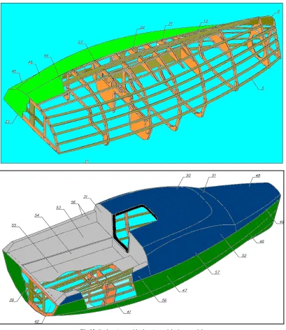
The drawings of the students of the model boat can be seen in Fig. 10 (wire drawings) and Fig. 11 (solid drawings). The printouts of these drawings were used by the students to construct the real model of the boat. Figure 12 shows the students' assembly drawings of the boat model.
Fig 10. Students' wire drawings of the boat model.
Fig 12. Students' assembly drawings of the boat model.
4.3. Construction of the Boat Model
The dimensions of the model were taken with a scale of approximately 1:10 relative to the dimensions of the boat prototype. Thus, the overall length and maximum width of the model are 600 mm and 200 mm, respectively. The big sail has a height of 600 mm and a base of 320 mm. The small sail has a height of 400 mm and a base of 255 mm.
The model was totally constructed by the students from wood. Wooden strips were used to construct the main frame (Skelton) of the model with necessary accessories. Suitable pieces of plywood were used to cover the frame to complete the model body. Then, the model surface was cover by a water-resistant coating. Finally, the model was carefully painted. The two sails were made from fabric. Fig. 13 shows the real model after fabrication.
4.4. Control
A control system was used to direct the sail model by controlling the model rudder. The control system consists of a control circuit and a stepper motor.
4.4.1. Control Circuit
The control circuit is manually operated by the operator of the model through electrical wires. Figure 14 shows the main
components of the control circuit. Theses main components can be summarized as:
1. Microcontroller:
A microcontroller is a computer-on-a-chip used to control electronic devices. It is a type of microprocessor emphasizing self-sufficiency and cost-effectiveness, in contrast to a general-purpose microprocessor such as the kind used in a PC. The microcontroller is programmed to guide the stepper motor to rotate to the right or left by a certain angle according to the signal of the right-left switch.
2.Right-left switch:
The switch controls the motion of the sail model by giving appropriate signals to the microcontroller. The duration of pressing the switch controls the angle of rotation of the stepper motor. The longer the pressing duration, the bigger is the rotation angle of the stepper motor.
3.Battery:
A set of DC batteries is used to supply the necessary current/voltage of the control circuit.
4.Screen:
A small LED screen is used to show the direction of rotation (right/left) as well as the magnitude of the rotation angle of the stepper motor.
Fig 14. Control circuit of the mono-hull model.
4.4.2. Stepper Motor
Stepper motor is a brushless, synchronous electric motor that can divide a full rotation into a large number of steps, for example, 200 steps. This is achieved by increasing the numbers of poles on both rotor and stator, Fig. 15.
Computer-controlled stepper motors are one of the most versatile forms of positioning systems, particularly when
digitally controlled as part of a servo system. Stepper motors are used in flatbed scanners, printers, plotters and many more devices.
Fig 15. Stepper motor [14].
5. Present Second Model
(Multi-hull Boat)
5.1. Description of the Boat Model
The second model represents a multi-hull boat that is known as catamaran. A catamaran is a multi-hulled vessel consisting of two parallel hulls of equal size. A catamaran is geometry-stabilized. It derives its stability from its wide beam, rather than having a ballasted keel like a mono-hull. A catamaran can have a very shallow draught. The two hulls will be much finer than a mono-hull's. Thus, the reduced drag allows faster speeds. Having no ballast, an upturned catamaran will be unlikely to sink [15].
A catamaran's two hulls are joined by some structure (frame). More sophisticated catamarans combine accommodation into the bridging superstructure. Catamarans may be driven by sail and/or engine. Originally catamarans were small yachts, but now some ships and ferries have adopted this hull layout because it allows increase speed, stability and comfort [15]. Figure 16 shows modern engine-powered ferry catamaran.
Fig 16. Engine-Powered Ferry Catamaran [15].
The second model resembles a class of boats that is known as "Tektron 50" [16]. Fig. 17 shows the overall shape of the model. The overall dimensions of the prototype (Tektron 50) and the second model are listed in Table 3. The reduction scale was intended to be 1:38. This scale was kept for the
overall length and width of the model. However, for constructional, stability and floating reasons, other dimensions were taken according to another scale of 1:25.
Fig 17. Overall shape of the second model [16].
Table 3. Overall dimensions of the prototype and second model.
No. Quantity Prototype
(Tektron 50) [16] Present Model
1 Length Overall (LOA) 15.24 m 40 cm
2 Loaded Waterline Length (LWL) 14.33 m 37.5 cm
3 Model maximum width 10 m 26 cm
4 Maximum beam at waterline (BWL) 1.02 m 4 cm
5 Width of Hull (B-hull) 1.08 m 4.25 cm
6 Height of Hull (H-hull) 0.58 m 2.5 cm
7 Draft 0.424 m 1.8 cm
8 Mid-Sec. Area 0.315 m2 5.3 cm2
9 Water Plane Area 10.288 m2 105.5 cm2
10 Displacement 2.5 m3 111.7 cm3
5.2. Design of Important Parts of Model
5.2.1. Sail Design
Figure 18 shows the main components of the sail.
5.2.1.1. Sail Forces and Moments
The heeling moment is caused on one hand by the sail heeling force acting in the center of pressure of the sails, and on the other hand the side force developed by the keel, the rudder and the underwater hull. This couple trying to overturn the boat is balanced by another couple, the righting moment, caused by the buoyancy of the boat and the weight of the keel and the hiking crew (these forces are not shown), Fig. 19 [18].
Fig 19. Sail forces and moments [18].
While the heeling force grows in a quadratic manner with wind speed, the heeling is best controlled by feathering the sails (twisting the head-off) and flattening them especially in the upper part. This lowers the aerodynamic center of effort, making it possible to keep the boat upright.
5.2.1.2. Defining a Sail
Fig 20. Definition of sail shape [18].
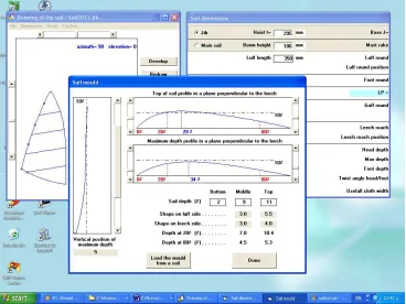
The shape of a sail section is defined with sufficient accuracy by two percentages and three angles: the camber, expressed in percentage of the local sail chord (width, 12%), the position of the maximum camber, similarly expressed in percentage of the local sail chord (47%), the twist expressed in degrees relative to the sail foot chord (10 degrees), the entry angle (32 degrees) and the exit angle (17 degrees), as defined in the illustration.
To define the geometry of a complete sail, we usually take three sections, at 25% - 50% - 75% heights, and the foot section plus the headboard. We also need to know the sheeting angle between the centerline of the boat and the foot chord of the sail, and the mast bend or forestay sag, to be able to fully describe one setting of the sail, Fig. 20 [18].
5.2.1.3. Parameters of Sail Design
Firstly, students had to obtain some data that will help them to make a proper design for the sail. The key word for designing a sail is the Main Sail Area, which is determined from empirical formulae. Most of these formulae give a range of possible values. So, the average value is usually considered.
The design procedure marches as [19-29]: Formula (1):
Sail area/Cubic root of (displacement)² = 15 - 17
For ratio =16, the sail area =371 cm² (1) Formula (2):
LWL × BWL × 2.75 = approximately sail area
Sail area =412 cm² (2) Formula (3):
Water plane area × 3.75 = sail area
Sail area = 398 cm² (3) Formula (4):
(Sail Area)²/(Displacement)² = 3.8 - 4
Sail area = 371 cm² (4) Then, from (1)-(4), the average sail area can be taken as 400 cm2.
5.2.1.4. Software Design of the Boat Sail
The sail was designed using software called "Sailcut". It is free software [30]. This software simplifies the design process as it contains the fundamentals of design, which allows designing a proper sail and jib for the sailing boat. The students designed about 14 alternative models for the sails of the Tektron-boat. Some of these sail models are accompanied by jib and some depend on main sail only. The model "sail 2012-jib" was chosen as it is the most familiar to the "Catamaran Sailing Boats".
5.2.1.4.(a). Sail 2012-jib (Main Sail)
Table 4. Main dimensions of the main sail.
No. Quantity Value
1 Luff Length 350 mm
2 Foot Length 200 mm
3 Diagonal Length 400 mm
4 Leech Length 402 mm
5 Sail Area 0.04 m²
6 Luff Round 10 mm
7 Luff round Position 50 %
8 Foot Round 10 mm
9 Leech Round 30 mm
10 Leech Round Position 60 %
5.2.1.4.(b). Sail 2012-jib (Jib Sail)
To obtain some information about the jib, students got some relations from other models and made sure that these relations are right by testing them on other detailed models [19-29]. Table (5) shows the relations between main sail and jib sail.
Table 5. Relations between main sail and jib sail.
No. Relation Ratio
1 Jib luff/Sail luff 0.8
2 Jib foot/Sail foot 0.54
3 Jib area/Sail area 0.36
4 Boom/Foot 1.02
Thus, the jib main dimensions are listed in the following table (6).
Table 6. Main dimensions of the jib sail.
No. Relation Value
1 Jib Area 0.0144 m²
2 Jib Hoist (Luff) 295 mm
3 Jib Base (foot) 108 mm
4 Boom/Foot 1.02
Fig. 21 shows the results of the design of the main and jib sails based on the above values of tables (4-6) and using "Sailcut" software.
Fig 21. Results of the design of the main and jib sails using "Sailcut" software.
5.2.2. Fin Keel Design
5.2.2.1. Definition and Advantages/Disadvantages
(i)Definition
The keel is basically a flat blade sticking down into the water from a sailboat’s bottom. It has two functions: it prevents the boat from being blown sideways by the wind, and it holds the ballast that keeps the boat right-side up.
Keels come in many styles. Traditional boats have graceful keels built into the shape of the hull; the ballast is either bolted to the bottom of the keel or placed inside it. The keel
is built of whatever the boat is built of, usually fiberglass, aluminum or wood, and the ballast is lead. This is a sturdy, time-proven design, especially good for a cruising boat, which might run aground on an uncharted reef or require hauling out in a remote part of the world [31].
A fin keel is much shorter (fore-and-aft) than a full keel, Fig. 22. A fin keel is often deeper, in order to move the ballast weight as low as possible in the water [32].
(ii) Advantages of fin keel sailboats [32]
length to resist the turning action of the rudder, a fin-keel boat turns more quickly and usually tacks easily. Most racing sailboats have fin keels (or a centerboard that is similarly shaped).
(iii)Disadvantages of fin keel sailboats [32]
Because the shorter keel provides less resistance to forces that act to throw a sailboat off course, such as wind gusts and waves, a fin-keel sailboat does not track as well as a full-keel boat and requires more attention to the helm. Its motion may not be as sea-kindly.
Fig 22. Shape of boat fin keel [32].
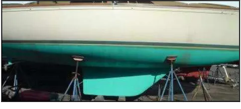
5.2.2.2. Keel of the Present Model
The keel of the present model takes the shape of an airfoil section. At first, the symmetrical airfoil section NACA 0010 was chosen due its simplicity and easy-manufacturability, Fig. 23a. Then, the airfoil section was changed to NACA 0010-66 as it gives better stability to the model, Fig. 23b. Two similar keels were manufactured. A keel was fixed to each of the two bodies of the boat model, Fig. 24. The keel has a length of 8 cm and a height of 5 cm.
(a) NACA 0010.
(b) NACA 0010-66.
Fig 23. Airfoil section of the present model [33].
Fig 24. Shape of the keel of the present model, not to scale.
5.2.2.3. Numerical Simulation of Keel
α = 0o
α = 20o NACA 0010
Fig 25. Continued.
fluid dynamics (CFD), the students carried out numerical simulation of the flow around the two airfoil sections NACA
0010 and NACA 0010-66 at different angles of attack. The
commercial software "Fluent 6.2" [34] was used to carry out the 2-D simulations. Fig. 25 shows the results of their simulations at two angles of attack (α).
α = 0o
α = 20o
NACA 0010-66
Fig 25. Computational predictions of the velocity contours of the keel sections.
5.3. Construction of the Second Model
The model was totally constructed by a professional craftsman from wood. The two hulls were made from two solid pieces of wood. The main part of the boat rests on a plywood piece that takes a rectangular shape. This rectangular wooden piece connects the two similar hulls of the model. Then, the model surface was cover by a water-resistant coating. Finally, the model was carefully painted. The two sails were made from fabric. Fig. 26 shows 3-D drawings of
Fig 27. Real model after fabrication.
5.4. Control
A control circuit similar to that of Sec. 4.4 of the mono-hull model was used to control the rudder rotation of the catamaran model.
6. Testing Channel Set
6.1. Description
A testing channel was designed and fabricated to test the two boat models. A closed circuit of water circulation was used to given enough water stream to test the two models. The channel length was designed to be at least 7 times the length of the sailing boat. The channel is designed to have maximum height of water equals 15 cm. This height gives maximum
volume of water equals 15 × 75 × 300 = 337500 cm3, Fig. 28.
(a) Drawing.
(b) Actual.
Fig 28. General view of the channel set.
6.2. Main Parts
6.2.1. Channel
Its main purpose is to accomplish a place that has uniform flow of water for testing the motion of the sailing boat. The pump draws water from the tank and elevates it to the main channel to have enough quantity of water to move the sailing boats.
6.2.2. Barrier
Its purpose is to avoid flow turbulence and avoid waves. Thus, the flow becomes uniform. It is located 25 cm form beginning of the channel.
6.2.3. Base
6.2.4. Tank
It stores a volume of water that is sufficient to supply the channel with the necessary amount of water to carry out the experiments.
6.2.5. Pump
It supplies the channel with the necessary amount of water to carry out the experiments. Also, it grantees the continuous circulation of the water stream during the experiment.
6.3. Dimensions and Specifications of the Main Parts
Table (7) shows the dimensions and specifications of the main parts of the channel set.
Table 7. Dimensions and specifications of the main parts of the channel set.
Part Quantity Value
Channel
Length 300 cm
Width 75 cm
Height 20 cm
Volume 300 × 75 × 20 = 450000 cm3 Wall thickness 0.15 cm
Material Iron Sheets
Tank
Length 100 cm
Width 75 cm
Height 50 cm
Material Iron Sheets
Door 20 × 20 cm2
Base
Length 300 cm
Width 75 cm
Height 120 cm
Thickness 3.0 mm
Material Iron
Pump
Type Centrifugal
Maximum Head 40 m
Volume flow rate 5-40 L/min
Power 0.5 hp
Frequency 50 Hz
Voltage 220 V
7. Experimental Tests
The objective of the experimental tests is to confirm the proper operation of the two sailing boats. The tests were performed in the water channel. These tests demonstrated the proper floating and cursing of the sailing boats as well as confirmed the operation of control circuits and the steering operation. Air blowing was generated by a suitable blower. All the tests were recorded by a suitable video camera. Students were guided to solve the uprising technical problems that appeared during the tests, Fig. 29.
As expected, the mono-hull model faced some instability problem. This problem was solved by carefully adding additional two small barrels; one on each side of the model. On the other, the multi-hull (catamaran) model did not face any stability problems at all.
Tests showed that control circuits operate well. The objective of proper steering and maneuver of the two models is well-performed. Moreover, the designed sails gave the models a suitable thrust to move and accelerate them. Sometimes, the wire connection causes shift in the boat
direction while cursing.
Fig 29. Experiments in the channel set.
8. Internet Dissemination
As part of the activities of the students and to teach them how to disseminate for their work, the author advised the students to initiate an internet group for their project.
Fig 30. Shoots of the Yahoo-group.
9. Conclusions
Based on the above illustrations and test observations, the following points can be stated:
1.The hands-on learning method confirmed to be very effective technique for the understanding and construction of multidisciplinary engineering systems. 2.Students sufficiently learned that optimization of the
design, material, manufacturing and construction gives a notable result in reducing the total cost of the engineering product.
3.The wire-connection of the control circuits causes shift in the boat direction while cursing. Thus, a wireless control method is recommended.
4.In spite of their simplicity, the control circuits proved to be suitable for the operation of the two model boats. 5.As expected, the mono-hull model faced some instability
problems. On the other, the multi-hull (catamaran) model did not face any stability problems at all.
6.The designed sails proved to be quite successful in gaining the required thrust to push the two models with a suitable speed.
Recommendations for Future Work
Based on the above discussions, the following recommendations can be listed:
1.The two boat models are to be used as demonstration tools for the students of: (i) "Fluid Mechanics Course"; especially the topic of "Stability of Floating Bodies" and "Wind Aerodynamics". (ii) Graduation projects as a real example of multidisciplinary engineering.
2.Distance sensors, depth sounder, and wireless digital camera are to be installed on the boat model with a suitable control circuit for safer operation.
3.The boat model may be supplied with Global Positioning System (GPS) to determine exact position and direction of the boat model.
4.Infra-Red (IR) or Radio-frequency (RF) control system is recommended to avoid the shift of the direction of the
boat model due to the wire-connection of the control circuit. RF system has the advantage of the longer range and more flexibility of control.
5.Other designs of the sails of the two boat models may be applied for better thrust force.
Acknowledgements
The author would like to acknowledge Engs. Ali M. Elkoshnea, Haitham A. Baz, Mohamed F. Elnagar, and Mahmod S. Elden of Mono-hull group as well as Mohamed Gaber and his colleagues of Multi-hull group as being members of the team of the B.Sc. Graduation project of the present work under the author's supervision. Also, acknowledgement is extended to Eng. Wael Elwan for his help in guiding the students.
Nomenclature
2-D Two-dimensional 3-D Three-dimensional A Bow transom (Mono-hull) B, C, D, E, F, G Sections of bulkhead (Mono-hull) H Transom (Mono-hull)
Hp Horse power
α Angle of attack
Abbreviations
NACA National Advisory Committee for Aeronautics B-hull Width of Hull
BWL Maximum beam at waterline CE Center of forces
CFD Computational fluid dynamics CLR Center of lateral resistance DC Direct current
foot Sail Base
GPS Global Positioning System H-hull Height of Hull
IR Infra-Red
LED light-emitting diode LOA Length Overall Luff Sail Hoist
LWL Loaded Waterline Length
NURB Non-Uniform Rational Basis Spline PC Personal computer
RF Radio-frequency
[4] http://en.wikipedia.org/wiki/Sloop
[5] http://www.catboats.org/index.php
[6] http://en.wikipedia.org/wiki/Sunfish_(sailboat)
[7] https://en.wikipedia.org/wiki/Catamaran
[8] http://en.wikipedia.org/wiki/Schooner
[9] http://en.wikipedia.org/wiki/Ketch
[10] http://en.wikipedia.org/wiki/Yawl
[11] http://mateykatsarski.blog.bg/hobi/2010/01/04/proekt-na-malk ata-iahta-quot-pilgrim-590-quot.466300
[12] http://sourceforge.net/projects/freeship/
[13] http://download.cnet.com/Freeship/3000-6677_4-10558861.ht ml
[14] http://simple.wikipedia.org/wiki/Stepper_motor
[15] http://en.wikipedia.org/wiki/Catamaran
[16] http://tek-composites.com/images/50ft_cat_cruiser/tek50c.php
[17] http://sail-lbs.com/?p=54
[18] http://www.wb-sails.fi/Portals/209338/news/98_11_PerfectSh ape/Main.htm
[19] Brewer, Ted (1994) Understanding Boat Design 4th Ed, International Marine
[20] Bruce, Peter (1999) Adlard Coles' Heavy Weather Sailing 30th Anniversary Ed, International Marine
[21] Chapelle, Howard I. (1967) The Search for Speed under Sail 1700-1855, WW Norton and Company
[22] Gerr David (1992) The Nature of Boats, International Marine
[23] Garrett, Ross (1996) The Symmetry of Sailing: The Physics of Sailing for Yachtsmen, Sheridan House
[24] Johnson, Peter (1971) Yachtsman's Guide to the Rating Rule, Nautical Publishing Co.
[25] Larsson, Lars and Rolf Eliasson (1994) Principles of Yacht Design, McGraw Hill
[26] Marchaj, C.A. (1964) Sailing Theory and Practice, Dodd, Mead & Company
[27] Marchaj, C.A. (1996) Seaworthiness: The Forgotten Factor, Adlard Coles Nautical / Tiller
[28] Marshall, Roger (1986) A Sailors Guide to Production Sailboats, Hearst Marine Books
[29] Technical Committee of the Cruising Club of America, John Rousmaniere Ed (1987) Desirable and Undesirable Characteristics of Offshore Yachts, W.W. Norton & Company
[30] www.sailcut.com.
[31] http://www.discoverboating.com/resources/article.aspx?id=25 1
[32] http://sailing.about.com/od/typesofsailboats/ss/Keelshapes_2.h tm
[33] http://www.airfoildb.com/
![Fig 4. Center of forces (CE) and center of lateral resistance (CLR) [3].](https://thumb-us.123doks.com/thumbv2/123dok_us/8572088.1716912/2.595.80.254.623.732/fig-center-forces-ce-center-lateral-resistance-clr.webp)
![Fig 5a. Sloop boat [4].](https://thumb-us.123doks.com/thumbv2/123dok_us/8572088.1716912/3.595.99.233.73.206/fig-a-sloop-boat.webp)

![Fig 17. Overall shape of the second model [16].](https://thumb-us.123doks.com/thumbv2/123dok_us/8572088.1716912/12.595.312.547.118.290/fig-overall-shape-second-model.webp)
![Fig 19. Sail forces and moments [18].](https://thumb-us.123doks.com/thumbv2/123dok_us/8572088.1716912/13.595.51.282.550.736/fig-sail-forces-and-moments.webp)