Outrigger Structural System – A Review and
Comparison of the Structural System
Prof. N. G. Gore, Miss Purva Mhatre Assistant Professor, Post Graduate Student
Mahatma Gandhi Mission’s College of Engineering and Technology, Navi Mumbai, India
Abstract
The paper presents a brief understanding of the concept of Outrigger system and explains its structural composition and advantages. The paper explains the different types of outrigger – conventional, offset and virtual. It tries to establish advantages of virtual system over others. Although theoretically conceptualized, the structural system has potential to suit the requirements and demands of a structurally and economically viable tall building. The paper presents an elaborate comparison of the lateral load resisting systems and also compares the virtual system with the conventional outrigger system.
Keywords — Lateral loads resisting buildings, conventional outrigger, virtual outrigger, seismic load, wind load, lateral displacement, and storey drift.
I. INTRODUCTION
The never ending human quest to reach the sky has developed far more from its historical advancements. Continuous research in the field of materials, construction technology and development of analysis soft-wares and operating systems has facilitated the construction of the modern marvels of the 21st century. These tall buildings have come to define human dominance and have essentially become a symbol of status and social & economic well-being of a country.
Though fancy on the outward, high-rise buildings are a result of pioneering architecture, calculated engineering and shear hard-work. As the height of building increases, it is subjected to the action of lateral (horizontal) loads – seismic forces and wind forces. Intensity of seismic forces varies with the location of the building. Wind forces increase parabolically with the height of the building. Seismic forces are more intense in comparison to wind forces, but are shorter in duration. Apart from the vertical loads (dead and imposed loads), tall buildings are essentially designed to resist the lateral loads acting on these buildings.
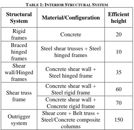
II. STRUCTURALSYSTEMSFORTALL BUILDINGS
In the modern era, tall buildings are designed majorly using the following structural systems: Interior system: When the major part of lateral
load resisting system is located within the interior
of the building, it is known as interior structural system. A brief comparison of various interior structural systems is shown in the table below:
TABLE 1: INTERIOR STRUCTURAL SYSTEM
Structural
System Material/Configuration
Efficient height
Rigid
frames Concrete 20
Braced hinged frames
Steel shear trusses + Steel
hinged frames 10
Shear wall/Hinged
frames
Concrete shear wall +
Steel hinged frame 35
Shear truss frame
Concrete shear wall +
Steel rigid frame 60 Concrete shear wall +
Concrete rigid frame 70
Outrigger system
Shear core + Belt truss + Steel/Concrete composite
columns
150
Exterior system: If the major part of the lateral load resisting system is located at the building perimeter, it is called exterior structural system. The table below compares different types of exterior systems:
TABLE 2: EXTERIOR STRUCTURAL SYSTEM
Structural System Material/ Configuration
Efficient storey
limit
Tube
Framed tube Concrete 60
Braced tube Concrete 100
Bundled
tube Concrete 110
Tube in tube Ext. frame tube +
Int. core tube 80
Diagrid Concrete 60
Super frames Concrete 100
III.OUTRIGGERSTRUCTURALSYSTEM
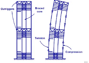
The outrigger structural system is a lateral load resisting system in which the external peripheral columns are tied to the central core with very stiff outriggers and belt truss at or more levels. The belt trusses are tied to the peripheral columns of the building while the outriggers engage them with main or central shear wall. This structural system is commonly used as one of the structural systems to efficiently control excessive drift due to lateral load, so that during small or medium lateral load due to either wind or earthquake, the risk of structural and non-structural damage is minimized. The structural response of an outrigger system is based on tension-compression couple induced in the outer columns. The outrigger acts as a stiff arm engaging outer columns and central core. The lateral load when induced in the central core is transferred to peripheral columns via outriggers and the overturning moment reduced.
...
Fig 1: Structural response of Outrigger
For high-rise buildings, particularly in seismically active zone or wind dominant regions, outrigger system is chosen to be appropriate structural system. Outrigger structural system is broadly classified into the following:
Conventional outrigger system: In this system, the outrigger trusses or girders are connected directly to shear walls or braced frames at the core and to the columns located at the periphery of the structure.
Offset outrigger system: In offset outrigger system, the outriggers are located elsewhere than in the planes of the core walls while retaining all the advantages and mitigating some of the disadvantages of the conventional outrigger system.
Virtual outrigger system: In virtual outrigger system the transfer of overturning moment from core to peripheral columns is achieved without a direct connection between the peripheral columns and the core. This is achieved using floor diaphragms which transfer overturning moment in the form of a horizontal couple from core to the outboard. A belt truss connecting the peripheral is also added.
IV.LITERATUREREVIEW
The concept of outrigger system is drawn from the use of a contraposing float rigging beyond the side of a boat to improve the vessel’s stability against wind in the sea. This simple mechanism sophisticated modern researchers’ minds to develop outrigger structural system. Successful projects have been built with the outrigger concept. A lot of research has been done in understanding outrigger typologies, material use, placing and connections and efficient positioning of outriggers.
Andrew J. Horton in ‘Virtual Outriggers in Tall Buildings’ has given an elaborate overview of conventional, offset and alternative offset outriggers. His paper concludes that virtual outriggers can be used with the same efficiency as conventional outriggers when efficiently proportioned perimeter belt truss and floor diaphragms are used.
Smith and Coull made a hypothetical assumption that the outriggers are flexurally rigid and devised for the optimum – the outriggers should be placed at 1/(n+1), 2/(n+1), up to the n/(n+1) height locations, i.e. for one-outrigger structure at approximately half-height, for two-outrigger structure at one-third and two-third height, for three-outrigger structure at one-quarter, one-half and three-quarter heights, and so on.
R Shankar Nair explained the advantages of virtual outrigger system over the conventional type and explained the ways of using virtual outrigger system. The paper compared lateral displacement of 75 - storey model subjected to wind load for different structural designs. The results obtained are as follows:
TABLE 3: COMPARISON FOR LATERAL DISPLACEMENT
Structural System Lateral displacement
No outrigger 108.5 inch
Conventional Outrigger 25.3 inch Belt truss as virtual Outrigger 37.1 inch Belt truss as virtual Outrigger: 10
fold increase in floor diaphragm stiffness
31.0 inch
Belt truss as virtual Outrigger: 10 fold increase in floor diaphragm stiffness, 10 fold increase in floor
belt truss stiffness
26 inch
Po Seng Kian and Frits Torang Siahaan studied the use of outrigger and belt truss system in high-rise concrete buildings of 40 and 60 storeys subjected to wind and seismic load. The paper concluded that the use of outrigger and belt-truss system in high rise buildings increases the stiffness and made structural form efficient under lateral loads.
numerical equations for analysis of multi-outrigger systems subjected to uniformly distributed load, horizontal load and triangular load.
Z. Bayati gave light on the use of optimum number of outrigger systems in a building using a 80 storey model and investigating on drift reduction. The results imply that optimized use of multi-outrigger system effectively reduces the seismic response of a building.
N. Herath reviewed the behaviour of outrigger beams in high rise buildings under the influence of seismic loads. The optimum outrigger location is determined at 0.44-0.48 times the height of the building.
S. Fawzia, et al studied the effects of cyclonic winds on 28, 42 and 47 storey buildings of L –shaped layout. The results show that the plan dimensions have vital impact on structural heights. Also, increase in height with same plan dimensions leads to reduction in lateral rigidity.
Hi Sun Choi and Leonard Joseph outlined a detailed approach for design considerations in outrigger system. It gives design guidelines for conventional and virtual outrigger system. It explains factors like structural aspects, load transfer paths, optimum location of outrigger, diaphragm floors, stiffness reduction, differential shortening of columns and thermal impact.
V. EXISTINGTALLBUILDINGSWITH OUTRIGGER
Technological advancements and continuous research have metamorphically made reaching the stars a reality. Buildings with heights as high as 800 m have been conveniently built. But at such heights, resisting lateral loads are a challenge; which are vigilantly tackled by engineers by careful selection of suitable lateral load resisting system. A number of noted buildings around the world have outrigger frame structural system which has proven efficiency to effectively resist lateral loads and provide structural serviceability. Existing buildings have made use of conventional outrigger system as well as offset outrigger system. The table below lists few of the popular tall-buildings round the globe using outrigger system:
TABLE 4:SKYSCRAPERS WITH CONVENTIONAL
OUTRIGGER SYSTEM
Building City Details #
Burj Khalifa Dubai 828 m 160 floors 5
Taipei 101 Taipei 509 m
101 floors 11 Shanghai Worlds
Financial Centre Shanghai
492 m 101 floors 8
International Hong 483 m 4
Commerce Centre Kong 118 floors Petronas Twin
Towers
Kuala Lumpur
452 m 88 floors 1 Nanjing Greenland
Financial Centre Nanjing
450 m 89 floors 3 Trump International
Hotel & Tower Chicago
423 m 96 floors 3
#: Number of Outrigger levels in the building
The 163 storey and 828 m tall Burj Khalifa is a ‘Y’ shaped building constructed in 2010 in Dubai, UAE.
The world’s tallest building is a reinforced concrete structure using high strength concrete of 60-80 MPa throughout the height of the building. The central hexagonal core is buttressed by wing shear walls with each wing having outriggers connecting shear walls to external columns.
A composite building with a 63.5 x 63.5 m square cross section at the base, the building has 8 modules of truncated pyramid. High strength concrete of 70 MPa is used and the structure has 8 perimeter mega columns and 16 core columns – all composite.
Constructed in 1998, the Petronas Towers is a 452-m tall, 88- storey building reinforced concrete building in the shape of an 8-pointed star. Both towers of the building have identical shape and are connected at 38th floor by a two-storey deep outrigger.
The diameter of 16 perimeter columns varies from 240 cm at the bottom to 120 cm at the top. The reinforced concrete cores of both the buildings are sized 22.9 x 22.9 m
Although successfully used, the conventional outrigger system has its own disadvantages. Also, in contrast to the wealth of information and real life examples of conventional outriggers, there is a relative dearth in the exploration in the field of virtual and offset outrigger. Very few buildings have been made using these structural systems. They are:
TABLE 4:SKYSCRAPERS WITH OUTRIGGER SYSTEM
Building Details Outrigger information
Dubai Tower, Doha 438 m 90 floors
1 Conventional; 2 Alternative
offset Plaza Rakyat Office
Tower, Malaysia
382 m 79 floors
1 Conventional; 2 Virtual
Aston Apartments Residential Tower,
Sydney
90 m 30 floors
1 Alternative Offset
The only skyscraper with a virtual outrigger system is Plaza Rakyat in Kuala Lumpur. The construction of the 382 m tall-building started in 1990s but is still pending.
VI.VIRTUALOUTRIGGERSYSTEM
Virtual outrigger provides lateral stability to the building by no direct connection between the core and the peripheral columns. The load is transferred to peripheral columns via floor diaphragms which are stiffer in their plane. The concept of virtual outrigger presents a reasonably unique solution to the problems posed by conventional outrigger.
The main feature of virtual outriggers is the use of
diaphragm floors. Understanding the behaviour of floor diaphragms is important for efficient functioning of a structure with virtual outrigger as lateral load resisting system. Diaphragm floor is a stiff & strong floor placed at the top and bottom of the virtual outrigger storey, at the periphery of which belt wall or belt truss is used to connect external columns. The diaphragm transfers the overturning moment from the core to external columns and the belt truss/wall distributes it equally throughout.
Virtual outriggers function in a similar way to that of a conventional outrigger, but the method employed varies. The working of virtual outriggers in explained in the following texts:
Belt trusses as virtual outriggers: The overturning moment in the core is converted into a vertical couple at the exterior columns. The rotation of the core is resisted by the floor diaphragms at the top and bottom of the belt trusses; thus, part of the moment in the core is converted into a horizontal couple in the floors. The horizontal couple, transferred through the two floors to the truss chords, is then converted by the truss into vertical forces at the exterior columns.
Basement as virtual outriggers: The basement of a tall building can serve as a virtual outrigger by creating a base with greater effective width for resisting overturning. This can reduce lateral load-induced forces in foundation elements and eliminate uplift. Since basement walls are typically of ample strength and stiffness as outriggers, there may be little additional cost involved in applying this concept.
VII. CONVENTIONALVS.VIRTUAL OUTRIGGER
But in-spite of these advantages, conventional outrigger has the following drawbacks:
The space occupied by the outrigger trusses causes constraints on utility floors at which outriggers are located. Even in mechanical equipment floors, the presence of outriggers can be a major problem.
Architectural and functional reasons limit the placement of large outrigger columns.
The connections of the outrigger trusses to the core can be very complicated, especially in the case when a concrete shear wall core is used. In most instances, the core and the outrigger
columns will not shorted equally under gravity – causing differential shortening.
These disadvantages of conventional outriggers present a number of challenges for the architects, engineers as well as users. Virtual outriggers present a polished solution to the problems presented by the conventional type. Benefits of virtual outriggers over conventional outriggers are as follows:
No trusses in the space between the building core and building exterior.
Complications caused by differential shortening of the core and the outrigger columns are avoided. Fewer constraints on the location of exterior
columns.
Strenuous connections of the outrigger trusses to the core are eliminated.
All exterior columns participate in resisting overturning moment.
Exterior framing consists of simple beam and column framing without the need for rigid frame type connection, thus reducing the overall cost. It is not affected by differential inelastic vertical
deformations between core and perimeter, so no vertical load transfer occurs between the core wall and perimeter columns.
VIII. CONCLUSION
High-rise buildings are the essence of modernisation and structural systems define their existence. Different structural systems have proved to be suitable at different locations and for different architectural and aesthetic requirements. Outrigger structural system has evolved since late 20th century to give the world modern marvels. Conventional outrigger system is no doubt a very efficient and reliable model of structural system, but the scope of improvement cannot be denied. Virtual outrigger presents a unique solution to the needs of structural stability as well as commercial utility and economic viability of a building. When designed proportionately and with more research, the virtual outrigger system can also be employed skyscrapers with no wastage of space and easier connections. The possibilities in achieving optimisation in terms of
material as well as construction techniques for the virtual outrigger system are numerous.
IX.FUTURESCOPE
Virtual outrigger system is a widely known topic but is lacks sufficient research. Analysis can be done to determine optimum depth of floor diaphragms, economic number of virtual outrigger storeys in a given height of building, material usage and optimum positioning of virtual outrigger in a given height of a building.
REFERENCES
[1] R Shankar Nair, Belt Trusees and Basements as Virtual Outriggers for Tall Buildings, Engineering Journal, Fourth Quarter, Page 140-146, 1998.
[2] PoSeng Kian & Frits Torang Siahaan, The Use of Outrigger and Belt Truss System for High-rise Concrete Structures, Dimensi Teknik Sipil, Volume: 0.33, Number: 01, Page 36-41, March 2001.
[3] J R Wu & Q S Li, Structural Performance of Multi-Outrigger-Braced Tall Buildings, The Structural Design of Tall and Special Buildings, Published online by Wiley INterScience, page 155-176, 2003.
[4] Z Bayati, M Mahdikhani & A Rahaei, Optimized use of Multi-Outrigger System to Stiffen Tall Buildings, The 14th
World Conference on Earthquake Engineering, October 12-17, 2008, Beijing, China.
[5] N Herath, N Haritos, T Ngo & P Mendis, Behavious of Outrigger Beams in High rise Buildings under Earthquake Loads, Australian Earthquake Society Conference, 2009. [6] S. Fawzia, A Nasir & T. Fatima, Study of Effectiveness of
Outrigger System for High-Rise Buildings under Earthquake Loads, International Journal of Civil Environmental, Structural, Construction and Architectural, Volume: 05, Number: 12, Page 789-797, 2011.