Page | 284
PERFORMANCE ANALYSIS OF DOUBLY FED
INDUCTION MACHINE
Nitin Goel
1,
P.R. Sharma
2, Shashi Yadav
3 123Department of Electrical Engineering, YMCA University of Science & Technology, India
ABSTRACT
In this paper steady state performance of doubly fed induction machine has been studied. A modified equivalent circuit is used for analysis in which core losses and harmonics are ignored. Doubly fed induction machine in a wind turbine system gives desired electric power output at variable speed. Here represent performance analysis of doubly fed induction machine in term of stator and rotor power, developed mechanical power, net power, shaft power, stator and rotor reactive power and current with variation in machine speed from sub synchronous to super synchronous regions and variation in rotor injected voltage (excitation voltage). After finding the machine parameters, analysis is done by MATLAB/Simulink. It has been shown that at variable speed, excitation voltage would control the mode of operation of induction machine: generating mode and motoring mode.
Keywords:
Doubly fed induction machine, induction machine, wind energy, asynchronous operationI. INTRODUCTION
Electrical power is most widely used source of energy for industries, homes, work place. Electricity
generation by using non renewable sources (coal, oil, gas) causes enhanced green house effect, leading to the
warming of the earth’ atmosphere.The wind energy is emerging as potential source among various non
conventional energy sources. Almost every country across the world is promoting wind energy generation units
[1]. A single wind power plant can have an installed power of hundreds of MW today and thus the influence of
these plants on the transmission network can no longer be neglected. Wind power generation is continued to
increase worldwide, India has the fifth largest installed wind power capacity in the world [2] .The latest annual
report of installed wind power worldwide of 283 GW at 2012 year’s end, which is enough to cover 3.5% of the
world’s electricity demand. Traditionally, synchronous generators have been used for power generation but
induction generators are increasingly being used these days because of their relative advantageous feature over
conventional synchronous generators [3].
Page | 285
A wound rotor induction motor has a stator like the squirrel cage induction motor, but a rotor with insulatedwindings brought out via slip-rings and brushes. However, no power is applied to the slip rings. A wound rotor
induction motor may also act as a generator when driven above the synchronous speed. Since there are
connections to both the stator and rotor, such a machine is known as a doubly-fed induction generator (DFIG).
A modified equivalent circuit is used in the analyses in which core losses and harmonics are ignored. Steady
state analysis for such machines is essential to estimate the behaviour under actual operating conditions [3].
1.1.
DIFFERENT TOPOLOGY FOR ELECTRICITY GENERATION FROM WIND POWER
• Standard squirrel cage induction generator directly connected to the grid.
• Wound rotor induction generator with variable rotor resistance.
• Doubly fed induction generator.
• Direct drive synchronous generator.
The first one is simplest and oldest system that consists of a conventional directly grid coupled squirrel
caged induction generator. In this method no converter is required. In DFIG, the stator is directly connected with
grid but a converter is connected between rotor and grid. In this only a fraction of the total power produced is
fed through the power converter system. In direct drive synchronous generator, the power converter system is
connected between stator and grid [4].
Fig.2 Connection diagram of doubly fed induction machine
1.2.
MODES OF OPERATION
The induction machine can be operated in grid connected or excited mode. Induction generator in
self-excited mode is capable to generate the power even in the absence of power grid. This makes it to be most
useful generator for remote windy locations [6]. If the generator is running super-synchronously, electrical
power is delivered to the grid through both the rotor and the stator. If the generator is running
sub-synchronously, electrical power is delivered into the rotor from the grid. A speed variation of ±30% around
synchronous speed can be obtained by the use of a power converter of 30% of nominal power. Furthermore, it is
possible to control both active (Pref) and reactive power (Qref), which gives a better grid performance, and the power electronics enables the wind turbine to act as a more dynamic power source to the grid [6].
Grid
Page | 286
II. STEADY STATE ANALYASIS OF DOUBLEY FED INDUCTION MACHINE
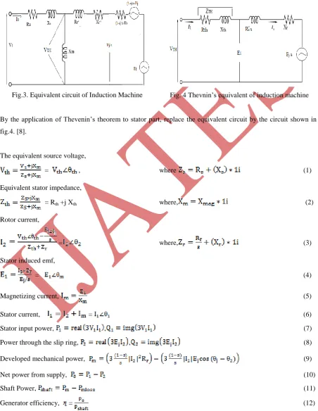
The steady state performance can be described by using equivalent circuit model shown in fig. 4. In this figure,
Vs is stator voltage and Ej is rotor injected voltages, I1and I2are the stator and rotor current, Rs and Rr are the
stator and rotor resistance, Xs and Xr are the stator and rotor leakage reactance, Xm is the magnetizing reactance
and s is slip[7].
Fig.3. Equivalent circuit of Induction Machine Fig. 4 Thevnin’s equivalent of induction machine
By the application of Thevenin’s theorem to stator part, replace the equivalent circuit by the circuit shown in
fig.4. [8].
The equivalent source voltage,
= , where (1)
Equivalent stator impedance,
= Rth +j Xth where, (2)
Rotor current,
= where, (3)
Stator induced emf,
= (4)
Magnetizing current, (5)
Stator current, = (6)
Stator input power, , (7)
Power through the slip ring, , (8)
Developed mechanical power, (9)
Net power from supply, (10)
Shaft Power, (11)
Page | 287
III. RESULTS AND DISCUSSION
In present study excitation voltage is applied at rotor side of machine and speed varies from sub synchronous
to super synchronous. Rating of machine has been taken as, 75 kW, 400 volts, 50Hz, 1480rpm. Excitation
voltage (rotor side injected voltage) varies from zero to 60 volts in five steps (0V, 15V, 30V, 45V and 60V) and
slip varies from -0.2 to +0.2. Fig-5 to 12 represents performance of doubly fed induction machine in term of
stator and rotor power, shaft power, mechanical power, net power, stator current, stator and rotor reactive power
with respect to slip.
Fig.5. Variation of stator power with slip Fig.6.Variation of rotor power with slip
Page | 288
Fig.9.Variation of net power with slip Fig.10. Variation of stator current with slip
Fig.11.Variation of stator reactive power with slip Fig.12.Variation of rotor reactive power with slip
Figures show that at various range of speed, injected rotor voltage would control the output of doubly fed
induction machine. At speed less than synchronous speed doubly fed machine give electrical supply through
stator side only but at the speed more than synchronous speed, machine give electrical supply through stator as
well as rotor side.
IV. CONCLUSION
The steady state analysis of a wound rotor induction generator is essential to understand the behaviour of doubly
fed induction machine such that it can operate at maximum power producing point for a given wind speed.
MATLAB programming is used to solve the proposed model. Depending on the supplied rotor voltage (Ej),
doubly fed induction machine is able to generate real power at rotor speed varies from sub-synchronous to
super-synchronous. Results shows that at sub synchronous speed only stator of doubly fed induction machine
give electrical power to grid. But at super synchronous speed stator and rotor both give electrical power to grid.
Reactive power in the stator and rotor winding of machine can be easily altered by adjusting the angle between
Vs and Ej. Analysis has been extended to recognize effectiveness of the machine parameters to improve the
operating performance of the machine.
REFERENCES
[1]K.S.Sandhu, and Dheeraj Joshi, “Estimation of control parameters of self-excited induction generator”,
International Journal of Circuits, Systems and Signal Processing, 3(1), 2009, 38-45
[2]Wind Power for Islands – Offshore and Onshore, 8th World Wind Energy Conference & Exhibition, Jeju Island, South Korea 23-25 June 2009
[3]G. Raina, and O.P. Malik, “Wind energy conversion using a self-excited induction generator”, IEEE Transaction on Power Apparatus and Systems, 102(12), 1983, 3933-3936
[4]L. Shridhar, B. Singh, and C.S. Jha, “A step towards improvements in the characteristics of self-excited
Page | 289
[5]H. Li, Z. Chen “Overview of different wind generator systems and their comparisons”, IET RenewablePower Generation, 2(2), 2008, 123– 138
[6]J.M. Elder, J.T. Boys, and J.L. Woodward, “Self-excited induction machines as a small low cost generator”,
Proceeding IEE, 131(2), 1984, .33-41
[7] Joris Soens, Karel de Brabandere, Johan Driesen and Ronnie Belmans “Doubly Fed Induction Machine:
Operating Regions and Dynamic Simulation”, Proceedings of 10th European Conference on Power Electronics and Applications, Toulouse, France September 2-4, 2003,1-10