R E S E A R C H
Open Access
View synthesis based on spatio-temporal
continuity
Li Yao
1,2*, Qiurui Lu
1and Xiaomin Li
1Abstract
Free viewpoint video is generated on the basis of a video plus depth (V+D) virtual point rendering framework. Because of the limited bandwidth of video transmission, depth-image-based rendering (DIBR) has become a common method. Most DIBR methods not only have holes and ghost artifacts but also have problems with time continuity, leading to frequent flickers. In this paper, we make full use of time domain information in video sequences and adjacent frames to extract the static background image of the whole scene. Furthermore, we propose a weighted-fusion hole-filling method based on static background to fill holes and maintain time continuity. Experimental results show that the proposed method can improve the quality of virtual view images and strengthen spatio-temporal continuity.
Keywords:Spatio-temporal continuity, DIBR, View synthesis
1 Introduction
Year 2010 is regarded as the breakthrough year of 3D video and the 3D industry [1]. Miraculous 3D films are delivered to the market, such as the first well-known masterpiece, Avatar. After Avatar, more and more excel-lent works have sprung up. By providing two different perspectives, the 3D film technology allows the audience to wear stereoscopic spectacles in the cinema, as if they are in the real scene. The prosperity of the 3D industry has led to the development of 3DTV, making 3DTV be-come the next generation after high-definition TV (HDTV). The free viewpoint video (FVV) is widely ad-dressed because of its better immersion and freedom to users.
How to use the existing known viewpoint videos to generate all the other needed viewpoint videos is a cru-cial technology for FVV. The common form of 3D scene is video plus depth (V+D). In general, the texture infor-mation comes from the video stream, and the geometric information of the scene is provided by the depth stream, which contains the distance between the object and the camera. The DIBR method makes use of the
texture and depth information of the known viewpoints to generate videos of other viewpoints, greatly reducing the burden on bandwidth. So that DIBR has become an important method in the FVV system.
Although DIBR can generate virtual images arbitrarily, the quality of virtual images is not satisfying because of the imprecision of the depth map and the occlusion be-tween objects. In the spatial domain, virtual image con-tains artifacts and holes. Artifacts are mainly due to the misalignment of color maps and depth maps, especially at the edge of objects. Meanwhile, there is a weak differ-ence in illumination between different referdiffer-ence points, making the pixel values from different reference points different. Apart from artifacts, holes are another challen-ging issue to be solved. They are mainly represented that some pixel positions on the virtual images have no warp-ing values. Holes can be classified into two types accord-ing to their causes: cracks and disocclusions.
Cracks are merely one to two pixels wide because of integer rounding error from reference views. By com-parison with cracks, disocclusions are larger holes con-tributed to unavoidable occlusion between objects, resulting in missing information in the virtual view.
In addition to the above issues in the spatial domain, the virtual video generated by the DIBR method has the time discontinuity. At present, the majority of the virtual view synthesis algorithms just deal with each frame
© The Author(s). 2019Open AccessThis article is distributed under the terms of the Creative Commons Attribution 4.0 International License (http://creativecommons.org/licenses/by/4.0/), which permits unrestricted use, distribution, and reproduction in any medium, provided you give appropriate credit to the original author(s) and the source, provide a link to the Creative Commons license, and indicate if changes were made.
* Correspondence:[email protected] 1
School of Computer Science and Engineering, Southeast University, Nanjing 211189, China
individually, but ignore the correlation information be-tween image frames and frames, leading to frequent flickering in the virtual video, especially at the edge of objects.
2 Related work
As for artifacts, the color difference between different reference viewpoints and the discontinuity of depth values of the object edges in the depth map are mainly concerned about. The literatures [2, 3] performed color correction by converting the color distribution between viewpoints by estimating the characteristics of the cam-eras. Fezza et al. [4] used an improved histogram match-ing algorithm for color correction in the common area of views, and used time sliding windows to maintain temporal correlation. Loghman et al. [5] used a multi-threshold segmentation method to distinguish the fore-ground from the backfore-ground, and mapped the different segments separately. Li Yao et al. [6] combine depth-based image fusion with direct image fusion to decrease the ghost effect. Luo et al. [7] extracted and separated the foreground objects and filled the holes with a rela-tively stable background obtained by the Gaussian mix-ture model. Although this method can effectively avoid artifacts, the construction of the background is very complicated and the parameters of the model are diffi-cult to choose.
As for holes, Do et al. [8] filled holes with distance-weighted sums of non-hole background pixels in eight directions around the holes. The exemplar-based image inpainting [9] can restore the hole texture information well. Daribo et al. [10] improved on the basis of the
Criminisi’s image inpainting algorithm by adding the
depth information. D M Motiur Rahaman et al. [11] used the number of models in Gaussian mixture model-ling (GMM) to separate background and foreground pixels, subsequently the missing pixels were recovered from the adaptive weighted average of the pixel inten-sities from the corresponding model(s) of the GMM and the warped image. Li S et al. [12] located useful pixels in the complementary views to reduce the holes.
Temporal continuity in the image sequence has also received the researchers’attention. Chen et al. [13] used motion vectors to obtain texture information from dif-ferent frames to fill holes. The literatures [14–16] distin-guish depth by the probability analysis, Gaussian mixture model, and structural similarity index, and ex-tracted static background information in the scene. Hsu et al. [17] used the global optimization method to fill holes and the image inpainting method used to make the background structure show the discontinuity of the spatial domain. Choi et al. [18] combined the current frame and the previous frames to find the best matching block of the hole. Muddala et al. [19] identified the
occlusion through layered depth images and used time frame information and motion estimation to repair it. Xi et al. [16] maintained temporal continuity by extracting
the scene’s static background image and measured the
temporal continuity using the peak signal-to-noise ratio (PSNR). Schmeing et al. [20] pointed out the importance of time continuity and introduced quantitative indicators for calculating the number of flicker. Liu et al. [21] pro-posed a full reference objective video quality assessment (VQA) method for temporal flicker distortion and changes in spatio-temporal activity in composite video. Although the abovementioned method has made many attempts in temporal continuity and can reduce the flicker of the video sequence to a certain degree, they do not address spatio-temporal continuity of the image se-quence, and therefore the quality of the virtual viewpoint image is unlikely to be satisfactory in both subjective and objective evaluation.
In this paper, we propose a virtual view synthesis based on spatio-temporal continuity. In order to main-tain the temporal continuity, we make full use of the time domain information in the video sequence and use the relationship between adjacent frames to extract the static background image, which can assist in solving arti-facts and holes. A weighted-fusion hole-filling method based on static background image is proposed, which not only solves the holes, but also maintains the tem-poral continuity, and avoids the flicker phenomenon to some extent.
3 Proposed view synthesis method
We propose a virtual view synthesis method based on spatio-temporal continuity. The framework is shown in Fig.1. The left and right reference points are combined to synthesize the virtual viewpoint in the middle with the left reference view as the main point. The static background in the scene is extracted from the adjacent frames of the reference viewpoint image sequence to keep the continuity of time. At the same time, a weighted-fusion hole-filling method is used to fill the remaining holes. The algorithm is executed in RGB color space and greatly improves the image quality of the vir-tual viewpoint.
3.1 Depth map processing
artifacts as much as possible, preprocessing the depth map is necessary.
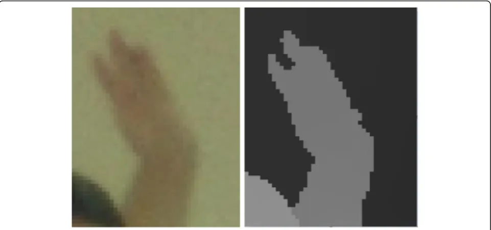
First, the edge contour of the object in the horizontal and vertical directions in the depth map is detected. The detection method is as follows:
dir ið Þ ¼ f;j 1−;D ið Þ−;j D iðþ1;jÞ≥T or D ið Þ−;j D ið;jþ1Þ≥T
1; D ið Þ−;j D ið−1;jÞ≥T or D ið Þ−;j D ið;j−1Þ≥T ð1Þ
where dir(i, j) represents the direction in which (i, j) pixel needs to expand,D(i,j) is the depth value of the (i,
j) pixel in the depth map, andTis a fixed threshold. There is one more point: the detected edge of the ob-ject is expanded in the direction of background. The position of the expanded pixels is as follows:
fi0¼iþdir ið Þ;j x
j0¼ jþdir ið Þ;j x ð2Þ
wherei′andj′are the horizontal and vertical coordi-nates of the expanded pixel position, and xis the num-ber of expanded pixels. The expanded edge pixel values are as follows:
D i0;j¼D i;j0¼D ið Þ;j ð3Þ
Gaussian smoothing is performed on pixels with large difference of depth between the foreground and background after expansion, and the depth image is traversed in the horizontal direction in order to com-pare the difference between each two adjacent pixel points with a preset threshold value. The filter area in
Fig. 1The diagram of the proposed view synthesis method
the image is found, and Gaussian smoothing is ap-plied to all pixels in the area. The filter area is deter-mined as follows:
filterð Þ ¼ fi;j True; D ið Þ−;j D ið;j−1Þ≥T or D ið Þ−;j D ið;jþ1Þ≥T
False; others
ð4Þ
where filter(i,j) indicates whether the pixel needs Gaussian filtering.
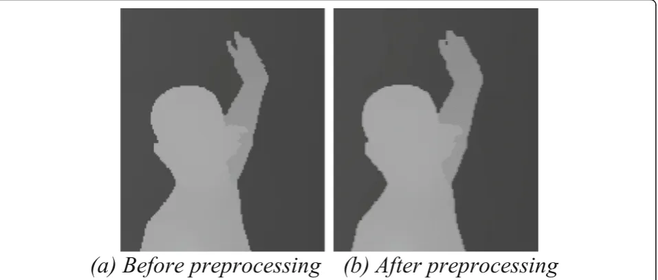
Figure 3 is a comparison of the depth map before
and after preprocessing. It can be clearly seen that the transition region of edge is relatively sharp before the depth map preprocessing. By filtering the depth map, the transition region of edge has become smooth and has been corresponding to the color map.
3.2 Static scene extraction
The connection between the frames is used to maintain temporal continuity. The static portions between every two frames are extracted and accumulated in the time direction.
The structural similarity measurement (SSIM)
method can extract the majority of the static scenes from images by comparing the similarity between two image pixels. Nevertheless, due to the occlusion between objects, some static backgrounds cannot be
distinguished and depth information must be
combined.
The global static background is constituted by the color image of the static background and the depth image of the static background, respectively initialized by the color map and the depth map at the first frame of
the reference viewpoint. The initialization process is as follows:
fCgð Þ ¼p Ctð Þp
Dgð Þ ¼p Dtð Þp t¼0 ð5Þ
where Cg is the global static background color map,
Dg is the global static background depth map, Ct and
Dtrepresent the color map and depth map of the
ref-erence viewpoint in frame t, and pis the pixel on the image.
After the initialization, the color map TCg and the
depth map TDgof the background at the current frame
can be extracted by comparing the current frame and the previous frame of the video sequence. For a common static pixel between adjacent frames, the calculated SSIM value is intensely large. The SSIM value between two pixels is calculated and denoted as PSSIM . The
for-mula is as follows:
P¼SSIM
2μφ
tμφt−1þK1
2σφt tð−1ÞþK2
μφt 2þμ
φt−1 2þK
1
σφt 2þσφ
t−1 2þK
2
ð6Þ
where φt and φt−1 are the corresponding matching
blocks in Ct and Ct−1 respectively, and the matching
block is centered on the pixel p, and the side length
is M. μφt and μφt−1are the average values of the
brightness of the corresponding matching blocks, and
σφt and σφt−1are the variances of the brightness of the corresponding matching blocks, respectively. σφtðt−1Þ is
the luminance correlation coefficient of the
corresponding matching block, and K1 and K2 are
constants.
When the PSSIM value is greater than a certain
threshold T1, the pixel is determined as a static pixel
denoted as Cs; otherwise, it is an undetermined pixel
denoted as Cr.
Static pixels Cs can be used to update TCg and TDg,
and the undetermined pixels require being further di-vided by depth information. The undetermined pixels can be divided into three types:
1. The same part of the object shows difference in brightness at different viewpoints. This part has a similar structural texture butPSSIMvalue is not very high, recorded asp1.
2. Due to the movement of the foreground object, background information occluded in the previous frame appears in the current frame, and these background pixels need to be extracted from the current frame. These pixels are denoted as p2.
3. The background information in the previous frame is occluded by the foreground in the current frame, and the background needs to be extracted from the previous frame. These pixels are denoted as p3.
The specific methods to divide the undetermined pixels are as follows:
fp∈p1∈Cr; jμ D
t−μDt−1j ≤T2 p∈p2∈Cr; μDt−μDt−1⊲−T2
p∈p3∈Cr; μDt−μDt−1⊳T2
ð7Þ
where μD
t and μDt−1 are the average depth values of
matching blocks, and T2is the depth difference
thresh-old. The first two types p1 and p2 are still background
pixels, so can updateTCgandTDg, and the third type p3
needs to be discarded in the current frame while using
the same position in the previous frame to update TCg
and TDg. Therefore, TCg and TDg can be extracted as
follows:
T Cgð Þ ¼ fp
Ctð Þ;p p∈Cs∪p1∪p2
Ct−1ð Þ;p p∈p3 ð
8Þ
TDgð Þ ¼ fp Dtð Þ;p p∈Cs∪p1∪p2
Ct−1ð Þ;p p∈p3 ð
9Þ
The background TCg and TDg extracted from each adjacent frame may be used to update the global static background Cg and Dg as follows:
Cgð Þ ¼ fp T Cgð Þ;p μ p TD−μ
p D≤T2
Cgð Þ;p others ð10Þ
Dgð Þ ¼ fp T Dgð Þ;p μ p TD−μ
p D≤T2
Dgð Þ;p others ð11Þ
where μpTD and μpD are average depth values of
match-ing blocks centered on pixel p in the depth maps TDg
andDg, respectively.
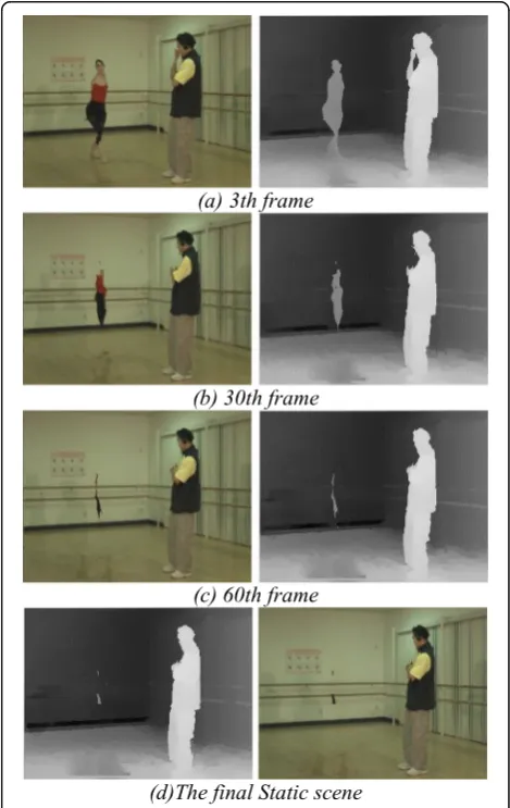
By extracting the pixels of adjacent frames, the static background image of the current frame can be updated, and at the same time, the global static background image can be updated with the depth information. Through the final extractable global static background image, useful information can be provided for subsequent holes. Fig-ure 4shows the results of the static background extrac-tion in different frames.
3.3 Forward warping fusion
The process of warping from the reference viewpoint to the virtual viewpoint is called forward warping.
First, the two global static background images ex-tracted from the previous step need to be mapped onto the virtual viewpoint imaging plane. Similarly, the left and right reference images need to be forward mapped to the same virtual viewpoint1.
After forward warping, two virtual images of the same position are generated, and the two virtual needs to be merged. The depth information of two pixel values is compared during the fusion, mainly based on the left viewpoint mapping. The fusion initialization method is as follows:
fCVð Þ ¼i;j CVLð Þi;j
DVð Þ ¼i;j DVLð Þi;j ð12Þ
where CV andDV are the color map and depth map of
the merged virtual viewpoint respectively, and CVL and
DVLare the color map and depth map warped by the left
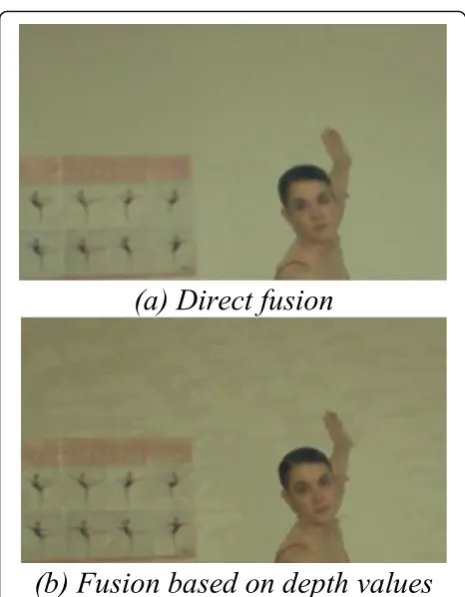
reference viewpoint, respectively. The fusion effect is
shown in Fig. 5. It can be seen that the image quality
based on the depth value fusion method is higher than that generated by the direct fusion method.
The warping result of the right reference viewpoint will assist in correcting the initial virtual viewpoint image as follows:
CVð Þ ¼ fi;j
CVð Þ;i;j others
CVRð Þ;i;j DVð Þ ¼i;j 0or DVð Þ⊲i;j DVRð Þi;j
ð13Þ
DVð Þ ¼ fi;j
DVð Þ;i;j others
DVRð Þ;i;j DVð Þ ¼i;j 0or DVð Þ⊲i;j DVRð Þi;j
ð14Þ
where CVR and DVR are the color map and the depth
map warped by the right reference viewpoint, respectively.
3.4 Artifacts elimination
Considering that the forward warping fusion is based on the result of the left view warping, it is necessary to detect the hole edge of the artifacts in the depth map of the virtual 1The datasets used in our study are MSR3DVideo-Ballet and
MSR3DVideo-Breakdancers, each of them contains images captured from eight cameras (say cam0~7). When we set the virtual viewpoint as cam4, the left and right reference images are images that captured by cam3 and cam5.
Fig. 5Comparison of two fusion methods.aDirect fusion.bFusion based on depth values
images, which are warped by the left reference view. The detection is done as follows:
Boundaryð Þ ¼ fi;j 255;
DVLð Þ ¼i;j 0&&DVLði;j−1Þ!¼0or
DVLð Þ ¼i;j 0&&DVLði−1;jÞ!¼0or
DVLð Þ ¼i;j 0&&DVLðiþ1;jÞ!¼0
0; others
ð15Þ
where Boundary represents the detected edge of the holes, with a pixel value of 0 (black) indicating a non-edge region and a pixel value of 255 (white) representing the edge region. The detected edge pixels of holes should not be all artifacts. In order to detect the artifacts, the fore-ground edge is extracted from the depth map of the left reference viewpoint and forward warped to the virtual viewpoint imaging plane. Subsequently we get the real ar-tifacts edge called Boundary_Artifact as follows:
Boundary Artifactð Þ ¼ fi;j 255;
Boundaryð Þ ¼i;j 255 && Boundary Foreð Þi;j!¼ð0;255;0Þ
0; others
ð16Þ
The artifacts can be eliminated effectively by marking the position of these pixels on the global static back-ground image as follows:
CVð Þ ¼ fi;j Cgð Þ;i;j if Boundary Artifact ið Þ ¼;j 255
CVð Þ;i;j if Boundary Artifact ið Þ ¼;j 0 ð17Þ
Figure6shows the virtual images after eliminating arti-facts. It can be seen that artifacts elimination method based on the global static background can improve the quality of the virtual images.
3.5 Weighted-fusion hole-filling method
The generated virtual viewpoint image still has some holes. These holes mainly appear in the background area, so the previously extracted global image of background is used to fill the holes. At the same time, in order to maintain time continuity, this paper proposes a weighted-fusion hole-filling method based on the static background. The specific steps are as follows:
Fig. 7Contrast of virtual images before and after holes filling.aThe virtual view before holes filling.bThe virtual view after holes filling
Table 1Characteristics of the test sequences
Test sequence
Resolution Camera setting Frame number
BreakDancers 1024 × 768
8 cameras with 20-cm interval
100
Ballet 1024 × 768
8 cameras with 20-cm interval
1. The holes in the first frame, the 1+L frame, the 1+2 L frame, and the subsequent frame are directly filled with the extracted global static background image. 2. For the middle frame between every two frames filled in
step (1), use the dynamic weighted fusion method for holes in the image. The specific method is as follows:
CVtþkð Þ ¼i;j ð1−weightÞCtVð Þi;j
þweightCtVþLð Þi;j ð18Þ
weight¼k modL
L ð19Þ
where CtVði;jÞ and CtVþLði;jÞare the virtual viewpoint images directly repaired by the global static background image in step (1), CtVþkði;jÞ is the virtual viewpoint
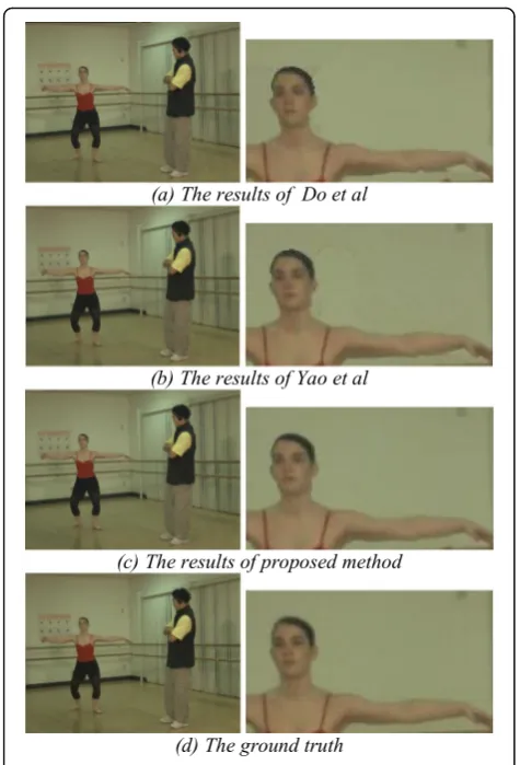
Fig. 8The results for“Ballet”sequence.aThe results of Do et al.b The results of Yao et al.cThe results of proposed method.dThe ground truth. From the enlarged detail image,we can see that (a) contains some errors around the arm of the ballet dancer; (b) contains some artifacts on the wall; (c) contains nearly no error or artifacts
image in step (2) that needs weighted fusion to fill in the
hole, and weight is the weight to be taken when
blending.
When using the image pixels in step (1) to fill other images, the image pixels must be background pixels. Therefore, the average value of depth DA in the global background depth image needs to be calculated.
CVð Þ ¼ fi;j
CVð Þ;i;j CVð Þi;j >0
CtþkV ð Þ;i;j CVð Þ ¼i;j 0&&DtVð Þi;j <DA&&DtþLV ð Þi;j <DA
0; others
ð20Þ
The final virtual viewpoint image is shown in Fig.7(b). It can be seen that the holes in the virtual viewpoint image are filled well compared with the holes in (a).
4 Results and discussion
We use “BreakDancers” and “Ballet” [22] to evaluate the performance of proposed method. The specific
parameters of the data set are shown in the Table 1.
In this paper, the left and right reference viewpoints are used to merge the middle viewpoint, and the final virtual viewpoint image is in comparison with the real viewpoint image. We will evaluate the
ex-perimental results by subjective and objective
indicators.
4.1 Subjective comparison
In order to compare the subjective quality, the refer-ence viewpoint 3 and the referrefer-ence viewpoint 5 are used in both datasets to generate the intermediate viewpoint 4.
This paper selects one frame of images from the two sequences to display the results, as shown in Figs.8and .9. The first row is the virtual images generated by Do et al. [8], the second row is the virtual images generated by Yao et al. [6], the third row shows our results, and the last row shows the ground truth images. From the
enlarged detail image in Figs. 8 and 9, we can see that proposed method eliminates artifacts and fills the holes best.
4.2 Objective comparison
We compare proposed method with other methods using PSNR and SSIM [23] on 100 frames, to evaluate the spatial continuity. It can be seen that proposed
method is best in PSNR and SSIM (Tables2and3).
F-score [20] is used as assessment of time continuity. TheF-score calculation method is as follows:
F−score¼jτtI−τtV j;∀t¼2:::Nf ð21Þ τt
D¼
1
φt jI
tð Þ−p It−1ð Þ j;p ∀t¼2:::N
f ð22Þ
where τt
I and τtV are the average absolute difference
between t frames of the real image and the virtual view image respectively. ∣φt∣ is the number of holes in the frame t. Itand I−1are the frame t andt−1 respectively.
Nfis the number of frames. Table4 shows the
compari-son results. The smaller the F-score number, the better the time continuity is maintained. It can be seen that proposed method works best. At the same time, as shown in Fig.10, theF-score value of proposed method is relatively uniform within 100 frames, and the overall transition is relatively smooth. This reveals that pro-posed method can continuously maintain the continuity of time in the entire video sequence. The virtual view-point images generated by Do et al. [8] and Yao [6] et al. have a poor effect on the temporality of the image
se-quence. Their magnitude of the F-score value is
rela-tively large, which is represented by multiple peak regions in the graph. This indicates that the pixel value transitions generated by the two virtual images have large jumps and there is no continuity in the time direction.
The proposed method can only be applied to the case of fixed camera. Experiments show that the proposed method can effectively solve the problems of artifacts, holes, and time continuity. During the experiment, it was found that if the reference view depth map was not accurate, the pixels with the same depth value would be mapped to different positions of the virtual view image, resulting in some flickers in the virtual view image, espe-cially at the foreground edge of the object. This problem needs to make full use of the correlation information
Table 2Result contrast for“Ballet”sequence
Method PSNR (dB) SSIM
Do et al. [8] 30.61 0.88
Yao et al. [6] 33.63 0.89
Our 34.28 0.90
Table 3Result contrast for“BreakDancers”sequence
Method PSNR (dB) SSIM
Do et al. [8] 31.94 0.85
Yao et al. [6] 33.27 0.86
Our 33.83 0.88
Table 4Time continuity comparison for“Ballet”sequence
Frame 9th 33th 54th 73th 96th 98th
Do et al. [8] 3.76 4.04 4.39 8.71 7.37 5.72
Yao et al. [6] 5.45 7.43 9.32 4.37 7.79 2.75
between depth maps. In addition, extracting static back-ground and filling holes take some time, and there is even more space for improvement in real-time.
5 Conclusion and future work
This paper proposes a virtual view synthesizing method based on spatio-temporal continuity. The static back-ground image of the entire scene is created. Further-more, we propose a weighted-fusion hole-filling method based on static background to fill holes and maintain time continuity. Our future work will focus on reducing the time cost. By analyzing the parallel processing in extracting the static background and filling the holes, CUDA can be used to further accelerate our algorithm.
Abbreviations
CUDA:Compute Unified Device Architecture; DIBR: Depth-image-based rendering; FVV: Free viewpoint video; GMM: Gaussian mixture modelling; HDTV: High-definition TV; PSNR: Peak signal-to-noise ratio; SSIM: Structural similarity index measurement; VQA: Video quality assessment
Acknowledgements Not applicable
Authors’contributions
YL was a major contributor in writing the manuscript. All authors read and approved the final manuscript.
Funding
This work is supported by natural science foundation of Jiangsu Province under Grant No.BK20181267, Industrial Prospective Project of Jiangsu Technology Department under Grant No.BE2018119.
Availability of data and materials
The datasets generated and/or analysed during the current study are available in the MSR repository,https://www.microsoft.com/en-us/download/ details.aspx?id=52358.
Competing interests
The authors declare that they have no competing interests.
Received: 15 April 2019 Accepted: 19 November 2019
References
1. A. Smolic, P. Kauff, S. Knorr, et al., Three-dimensional video postproduction and processing[J]. Proceedings of the IEEE.99(4), 607–625 (2011) 2. J.I. Jung, Y.S. Ho, Color correction for multi-view images using relative
luminance and chrominance mapping curves. Journal of Signal Processing Systems.72(2), 107–117 (2013)
3. F. Shao, G. Jiang, M. Yu, New color correction method of multi-view images for view rendering in free-viewpoint television. Wseas Transactions on Computers7(5) (2008)
4. S.A. Fezza, M.C. Larabi, K.M. Faraoun, Feature-based color correction of multiview video for coding and rendering enhancement[J]. IEEE Transactions on Circuits & Systems for Video Technology.24(9), 1486–1498 (2014)
5. M. Loghman, J. Kim, Segmentation-based view synthesis for multi-view video plus depth. Multimedia Tools & Applications.74(5), 1611–1625 (2015) 6. L. Yao, Y. Han, X. Li, Fast and high-quality virtual view synthesis from
multi-view plus depth videos[J]. Multimedia Tools and Applications9(2019)
7. G. Luo, Y. Zhu, Z. Li, et al., A hole filling approach based on background reconstruction for view synthesis in 3D video. Computer Vision and Pattern Recognition, 1781–1789 (2016)
8. L. Do, S. Zinger, P.H.N.D. With,Quality improving techniques for free-viewpoint DIBR.3dtv Conference: the True Vision - Capture, Transmission and Display of 3d Video(2010), pp. 1–4
9. A. Criminisi, P. Perez, K. Toyama, Region filling and object removal by exemplar-based image inpainting. IEEE Transactions on image processing.
9(13), 1200–1212 (2004)
10. I. Daribo, B. Pesquet-Popescu, Depth-aided image inpainting for novel view synthesis. IEEE International Workshop on Multimedia Signal Processing, 167–170 (2010)
11. D.M. Rahaman, M. Paul, Virtual view synthesis for free viewpoint video and multiview video compression using Gaussian mixture modelling[J]. IEEE Transactions on Image Processing (99), 1190–1201 (2018)
12. S. Li, C. Zhu, M.T. Sun, Hole filling with multiple reference views in DIBR view synthesis[J]. IEEE Transactions on Multimedia, 1–1 (2018) 13. K.Y. Chen, P.K. Tsung, P.C. Lin, et al., Hybrid motion/depth-oriented
inpainting for virtual view synthesis in multiview applications. The True Vision-Capture, Transmission and Display of 3d Video, 1–4 (2010) 14. W. Sun, O.C. Au, L. Xu, et al., Novel temporal domain hole filling based on
background modeling for view synthesis. IEEE International Conference on Image Processing, 2721–2724 (2012)
15. C. Yao, T. Tillo, Y. Zhao, et al., Depth map driven hole filling algorithm exploiting temporal correlation information. IEEE Transactions on Broadcasting.60(2), 394–404 (2014)
16. M. Xi, L.H. Wang, Q.Q. Yang, et al., Depth-image-based rendering with spatial and temporal texture synthesis for 3DTV. Eurasip Journal on Image & Video Processing.2013(1), 9 (2013)
17. H.A. Hsu, C.K. Chiang, S.H. Lai, Spatio-temporally consistent view synthesis from video-plus-depth data with global optimization. IEEE Transactions on Circuits & Systems for Video Technology.24(1), 74–84 (2014)
18. S. Choi, B. Ham, K. Sohn, Space-time hole filling with random walks in view extrapolation for 3D video. IEEE Transactions on Image Processing.22(6), 2429–2441 (2013)
19. S.M. Muddala, R. Olsson, M. Sjöström, Spatio-temporal consistent depth-image-based rendering using layered depth image and inpainting. Eurasip Journal on Image & Video Processing.2016(1), 1–19 (2016)
20. M. Schmeing, X. Jiang,Time-consistency of disocclusion filling algorithms in depth image based rendering.3dtv Conference: the True Vision - Capture, Transmission and Display of 3d Video(2011), pp. 1–4
21. X. Liu, Y. Zhang, S. Hu, et al., Subjective and objective video quality assessment of 3D synthesized views with texture/depth compression distortion. IEEE Transactions on Image Processing A Publication of the IEEE Signal Processing Society.24(12), 4847–4861 (2015)
22. C.L. Zitnick, S.B. Kang, M. Uyttendaele, et al., High-quality video view interpolation using a layered representation. Acm Trans Graph.23(3), 600– 608 (2004)
23. Z. Wang, A.C. Bovik, H.R. Sheikh, et al., Image quality assessment: from error visibility to structural similarity. IEEE Trans Image Process.13(4), 600–612 (2004)
Publisher’s Note