The White Goods Part Designed Based on DFM/DFA
Concepts in a Concurrent Engineering Environment
Osiris Canciglieri Júniora
aPontifícia Universidade Católica do Paraná (PUC-PR), Curitiba, Brazil
João Pedro Buiarskey Kovalchukb
b CNH – Case New Holland Latin America – Pontifícia Universidade Católica
do Paraná (PUC-PR), Curitiba, Brazil
Antonio Batocchioc
cFaculdade de Engenharia Mecânica, Universidade Estadual de Campinas
(UNICAMP), Campinas, Brazil
Abstract
The classical way to manage the product development processes for massive production has been changing as the high pressure for cost reduction, higher quality standards and market seeking for innovation lead to the necessity of new tools for development control. This context and the learning from the automotive, aerospace industries and others segments were the starting point to understand and apply manufacturing and assembly oriented designs to ease the task of generate goods and from this to obtain at least part of the expected results. This paper demonstrates the applicability of the concepts of Concurrent Engineering and DFM/DFA (Design for Manufacturing and Assembly) in the development of products and parts for the White Goods industry in Brazil (major appliances as refrigerators, cookers and washing machines), showing one case concerning to the development and releasing of a component. Finally, it shows, shortly, how using these techniques as a solution had provided cost savings and reduction in delivery time.
Keywords: Concurrent engineering, DFM/DFA, Design management, White
Introduction
The process of product development has been accelerated over the years. For the majority of the industries conceptual changing and costs reductions allied with the demand to release of the product into the market in the shortest time are today the way of work, especially for the White Goods (major home appliances as refrigerators, cookers and washing machines). Pressure caused by competent and strong competitors, reduction in markets and costumers that demand more value for money are now daily reality. Because of these highly aggressive conditions, the necessity for more suitable ways of managing product and component development has become higher than ever.
To match those conditions and using the example from the aircraft and automotive industries, the DFM/DFA and the Concurrent Engineering proved to be, by themselves, powerful alternatives to run the design management methods, bringing together some interesting advantages. Regarding to DFM/
DFA and Concurrent Engineering, Boothroyd (2001) affirmed that a winning
design can only be developed when the team responsible for the product is prepared to get in to the process and understand the way that the manufacturing works and behaves. This is close to what Huang (1996) stated about the reliable developer, who “must know the manufacturing to prevent unrealizable products due to the lack of intimacy with the productive process”. Agreeing to the previous authors and complementing, according to Boothroyd and Alting
(1992), Boothroyd and Dewhurst (2008) and Gautier et al. (2000) design must involve each single part and respect all opinions. However, the lack of one or more engineering groups can jeopardize the success of the product bringing unexpected problems that will increase costs.
All of the mentioned authors have showed a well known panorama - a design must be accepted and discussed by all teams responsible for the
product: the design area which is the conceiver of the product; the design engineering which will transform the sketch concept into a proposal; the process engineering that will prepare the factory for the design; the manufacturing that will release the concept into a tangible product; the quality team that will
approve the developed parts and processes and so on.
during the entire product life cycle, as well as the interoperability between systems that will supply these teams with right information in real time avoiding
duplication and unexpected data (CANCIGLIERI and YOUNG, 2003; YANG and MCGREAVY, 1996; AMEZIANE, 2000; WOHNHAS, 2003; TANAKA and KISHINAMI, 2006; FARINHA, JARDIM-GONÇALVES and GARÇÃO, 2007).
Therefore, this paper aims to show a product developed under this synergy, explaining, also how CE and DFM/DFA have helped designers and engineering teams to reach the target of developing a new and more affordable part, with quality improvements, reduced time of assembly and with shorter release time.
Reseach Methodology
Regarding to the research method, this research is an explanatory case study. According to Tellis (1997) and Yin and Moore (2001), this sort of case can use pattern-matching techniques that conduct the study to examine
the reason why some research findings get into practical use. The authors
used a well-founded research design as the unit of analysis, where the topic was a constant but the design was variable (MARSHALL, 1997).
The development of the case explored in this article, a complex part that replaced a set of parts which was already complete, functional and on normal production, was based on the methodology developed by Boothroyd (2001) e Boothroyd et al. (2002) which show that it is possible verify if one part may or may not be excluded from an assembly. The part grouping (process where the main objective is to decrease the number of the part from a complex multi-component and sub-assembly to a multifunctional single part) can be ruled by three simple questions:
1) Does the part need to have a relative movement to the others parts located/positioned around (conditions concerns movement)?
2) Does the part need a different kind of material from the others around it?
3) Is the analysis of the part presents any impeditive to be assembled to another part? If there is any impeditive then must be repaired.
can be joined and assembled (no other request will give different result).The advantage is the simplicity of the analysis that can be done from the shop
floor to the design or from the engineering to the production, with no complex
data request or special resources. The answers to these 3 questions must be essentially three negative responses which mean that the part does not need to be separated from all of others parts that are located/positioned around.
From this and based on observations, studies, tests, researches and
literature review was identified an opportunity for application of DFM/DFA/CE
and a solution was proposed. The research was divided in phases. Firstly, there
was the identification of a design that could offer possibilities for improvement. Discussions over the deficiency of the recent management methods and
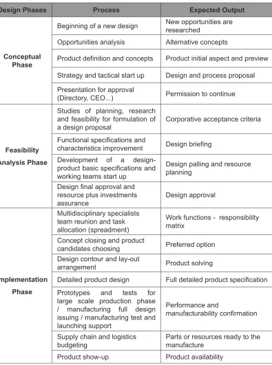
practices applied in the design/manufacture/assembly took place based on the literature review and cases observation. After that, opportunities to develop a new part using DFM/DFA/CE methods and concepts were raised then the application was chosen to be used as a demonstrative example. In the second phase these methods emphasized the process and controlling activities. In the subsequent phase the conceptual design was carried out as a product and the detailed methods were given to the engineering teams in order to them to share information supporting the multiple viewpoints. A detailed view of the process, including sub-phases and milestones can be seen in Table 1.
To understand each step of the method it is necessary to consider them separately. Firstly it must be understood that each stage has its own inputs and outputs and whether each of them are or are not independent of the others, this is the conceptual basis of the CE. Thus, it is necessary that the design is properly separated into phases: the conceptual development and the study of enforceability, and the implementation (Design Milestones).
The conceptual development phase began with the first sketches of
Table 1: Design Milestones - (adapted from Marshall (1997)).
Design Phases Process Expected Output
Conceptual Phase
Beginning of a new design New opportunities are researched
Opportunities analysis Alternative concepts
Product definition and concepts Product initial aspect and preview
Strategy and tactical start up Design and process proposal Presentation for approval
(Directory, CEO...) Permission to continue
Feasibility Analysis Phase
Studies of planning, research and feasibility for formulation of
a design proposal Corporative acceptance criteria
Functional specifications and
characteristics improvement Design briefing Development of a
design-product basic specifications and
working teams start up
Design palling and resource planning
Design final approval and
resource plus investments
assurance Design approval
Implementation Phase
Multidisciplinary specialists team reunion and task allocation (spreadment)
Work functions - responsibility matrix
Concept closing and product
candidates choosing Preferred option
Design contour and lay-out
arrangement Product solving
Detailed product design Full detailed product specification
Prototypes and tests for large scale production phase / manufacturing full design issuing / manufacturing test and launching support
Performance and
manufacturability confirmation
Supply chain and logistics
budgeting Parts or resources ready to the manufacture
In Feasibility Analysis Phase presented in this article were analyzed
the conceptual, economic, constraints and eventual needs of the specific design of the final part as well as its comparison with other solutions that could be the alternatives. Additionally, we have carried out technical, financial
and schedule phase-in of the new phase and phase-out of the former, taking into account the policies of assurance to the consumer part in the process of deactivation, the support phase-out the suppliers and the process of training and capacitation of the network of repair.
Afterwards, analysis of manufacturability and enforceability were needed. Therefore, information concerning the possibility of manufacturing the material, the criteria for acceptance of the areas involved have been clarified, as well as the processes throughout the resources, both financial and strategic,
were released. So that, it was determined the criteria which the design would
be defined and subsequently measured and verified and the analysis of the
supply chain, the production capacity and reliability of suppliers resulting on the approval of the design.
The Implementation Phase executed the concepts proposed in the previous phases (based on the methodology of DFM/DFA/CE). At this stage a chain of responsibility involving purchasing, logistics, engineering, quality, delivery and production teams were developed and the array of responsibilities has been properly constructed by assigning each area to their respective responsibilities. Also, the material acceptance was prepared following the
special design according to what was defined together with the supplier. The
mold and the prototypes were built and verified by the company responsible
and adjustments were made to both, the mold and the parts, in order to meet
the design specifications. Manufacturing was supplied and the part production
was performed. The part was, then, incorporated into the product structure
and the final assembly was requested and held, as a result, the functional part
of its allocation points was obtained concluding the implementation phase and
the final component was designed.
Concurrent Engineering and DFM/DFA
According to Dalgleish et al. (2000) communication and information
sharing are important to support all the design definition and execution phases
misinformation, unexpected redesign, reprocess or even the negligence of the necessities of design due to the lack of a strong team participation. Anderson
(1990) evidenced this saying that the design determinates approximately 80% of the product manufacturability cost. This cost estimation is a significant part
of the resources investment since they have already been allocated and any
later changes will be very difficult to be implemented as well as expensive (Figure 1). This figure highlights the dramatic increasing of costs when any
change in product occurs after the conception and design phases. The change means more expensive cost, and sometimes is not feasible to make it.
Figure 1: Cost estimation in product life cycle - (Adapted from: Anderson, 1990).
Therefore, this emphasizes the strong necessity of keeping in mind that any product and its generation must be well evaluated from the beginning of the process and as much opinion as possible be taken in consideration before the design reaches the feasibility analysis phase.
Concurrent Engineering and DFM/DFA versus Traditional Design
undesirable effects. All these problems must be added to other limitations such as: machine restrictions, low investments, narrowed-time schedules, space and logistics and so on. Therefore, the conceptual challenge is “how to develop
a new product finding the best cost-effectively in the shortest time, taking in
consideration all different opinions without loosing the acquired knowledge
about processes and also fitting the costumer necessities” (BRALLA, 1986;
KOTLER, 2007).
The design will determinate the manufacturability of a product even when it is considered a product with a very high level of sophistication, however it will not determinate the manufacture itself. In fact, this level of sophistication (maybe considered also as automatization) will reinforce the necessity of a
well-elaborated design (CANCIGLIERI and YOUNG, 2001; CANCIGLIERI,
2005).
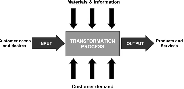
Traditionally a productive process has some basic steps, according
to Galdaméz and Branício (2001) as follows: i) the identification of customer’s needs and desires as an input; ii) an output represented by product or service to match the majority of the needing expressed in the input; iii) between them
a productive transformation process fed by information and resources (as materials and machinery) and iv) the market demands. All of them are depicted in Figure 2. However, this simple interpretation does not take in consideration
all the information that flows throughout the transformation process. Yet,
the information itself shows the limitations or it not expresses the needs for changing or improvements.
Customer needs
and desires TRANSFORMATIONPROCESS
Customer demand Materials & Information
Products and Services
INPUT OUTPUT
The modern White Goods factories have been working simultaneously with several products in one assembly line and it is not rare that a component is used in similar conditions on different platforms. This can happen even with different technologies, products or market segments. Also, most of the well known trademarks reduced the investments in new products making only upgrades to the existent ones, so that it is necessary to maintain, for at least a couple of years, the assembly line, methods and machinery to ensure the supply of spare parts for these products.
The apparent undesirable conditions may present a very good opportunity to rethink the product development process based on the: i)
experience obtained from previous designs; and, ii) the knowledge of where
the weakest points can reveal a path to start a production based on oriented design methodology.
Concurrent Engineering: Why?
Organizations learn with the time to improve their adaptability and
efficiency (BRINK, 2003). This idea reinforces the use of the previous mistakes
experience to speed up the development process as well as to accomplish new technologies and philosophies to ensure the activities must be faster and generates more precise information to the achievement of the target (Sivaloganathan et al., 2001).
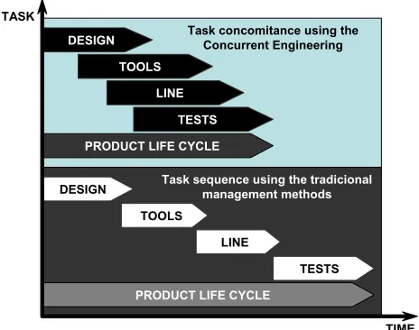
In this way, DFM/DFA and CE (both production oriented designs “ways”) offer a substantial advantage since they permit to run activities simultaneously, in opposition of the tasks sequencing. Also, they allow the use of simulation techniques and a full synergy between the teams making possible
to find design failures or deviations, fixing them before the development ends
(Sivaloganathan et al., 2001), as illustrated in Figure 3.
According to what have been exposed until now, applying the DFM/ DFA/CE to the White Goods industry reality permit faster product development with savings of time, money, work, but mainly with the higher step to hit required quality level and production standards through an assertive way
of development management. This clarifies why to use the resources of a
TASK
TIME
DESIGN
TOOLS
LINE
TESTS
PRODUCT LIFE CYCLE
Task concomitance using the Concurrent Engineering
DESIGN
TOOLS
LINE
TESTS
PRODUCT LIFE CYCLE
Task sequence using the tradicional management methods
Figure 3: Product life cycle between Concurrent Engineering traditional management methods – (Adapted from Rozenfeld et al., 2006).
Production Oriented Design Using CE and DFM/DFA: How?
Designers do not start a new design situation as newcomers or novices. Through education and practice they have acquired a vast repertoire of design solutions, which they carry out over the design task (FERNEDA, 1999). This knowledge may be the result of several mistakes, improvement opportunities or just good new ideas acquired due to development and research on design area. However, to acquire a high level experience in product manufacturability is not easy task.
Huang (1996) affirmed that reasons such as the increasing of the complexity level of the bundled technologies in the product; stress caused
by short time to deliver some output to the market; the pernicious philosophy
adopted by some designers (“we design, you assemble” or “we do sketches, you do products”); and the complexity of some industrial processes, invalidate
the simple idea of caring about the development of manufacturing reality. According Pasman (2003) a good injection plastic product development designer/engineer must understand: i) which material is more suitable to make
the part; ii) if the part can be assembled with other related product parts; and
iii) if the part or the product can be manufactures in the factory shop floor. This
around and must know his tasks perfectly to justify his work position. So, is it
possible that factory and design office work simultaneously?
Ferreira e Toledo (2001) has discussed how the using of design and manufacture techniques can “hear the voice of production line” and at the same time be virtually near to the information. Buss et al. (2001) agreed to this point of view stating that DFM/DFA/CE allow the designer and engineer bring considerations about the product assembly and manufacturability. Yet,
Buss Fagade and Kazmer (1998) and Maniscalco et al. (2005) defended that the most significant advantage of DFM/DFA is the encouragement for the
integration between design and manufacturing teams. This encouragement
will improve the reliability of the final product concept and it will generate
reduction of costs/time by decreasing the number of parts that are used in the product. So, the perspectives are clear, but now it is necessary to understand why the use of production oriented design and how to implement it, using the CE and DFM/DFA in an integrated way. The next section will clarify what should be done in order to integrate CE and DFM/DFA.
CE and DFM/DFA: What?
First of all it is necessary to understand well what are the necessities to drive a design using Concurrent Engineering techniques. For this, it is important
to define the product conception as a multiple responsibilities tasks. From the
first conceptual sketch to the final packed assembled delivered product there
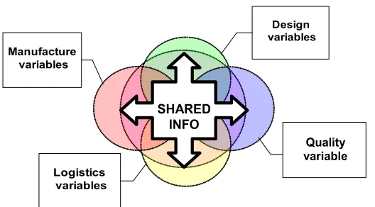
are many necessities. Canciglieri and Young (2003) and Sacchelli (2005) stated that in a multiple viewpoint manufacturing and design system all the opinions must be considered among interdependent domains as shows Figure 4. Thus, the common overlap points must be decided in an intelligible form that can allow all the elements of the productive chain to express their necessities and limitations clearly to any other part connected to it.
In addition, it is essential letting all the teams warned that the design is designed based on manufacture and assembly constraints, meaning that all attention is focused on product development and the manufacture must always be heard. The time of processing, the quantity of staff, tools for assembly,
in-line stocks and other typical variables that emerged from the shop floor
are vital for the development. Different variables must express themselves as factory improvements or assistances. To be able to resolve the variables
Logistics variables
Quality variable
s
Design variables Manufacture
variables
SHARED
INFO
Figure 4: Interdependence of variables (opinions) for a DFM/DFA driven development - (From: Kovalchuk, 2006).
sharing/translating and data optimization are basic requirements on a CE driven development.
The sharing of information has the reason on its own because different domains working in a concurrent way might need access to the same kind of information. The variables in the system are quite complex when analyzed locally, but once put together they are virtually different forms observing the same necessities. An example of it is the task of reducing man work to save costs. For sharing information, one suggestion is to make the assembly task as simple as possible by decreasing the number of parts. For the manufacturing specialist point of view this represents an economy of work and time to
accomplish the task; for the logistics specialist this means fewer parts to
administrate, and for the quality expertise less components that might present a failure. All these outputs will be inputs to the designer who must think on multifunctional compact part. Nevertheless all of the information is generated by the necessity of save costs in the assembly.
Concurrent Engineering: When?
The last part of development with CE and DFM/DFA techniques is related to the time management. According to Table 1 and Figure 3 activities should run parallel in a design. But when is the time to carry over a new task? To answer this question, Capucho et al. (2000) had observed that in multidisciplinary teams, the behaviour of the local rework caused by an activity with adverse results is much smaller then a global restructuring of a design and a global redesign might be impossible due to the costs. According to Hartley
(1998) the inclusion of a change in a running design is more expensive as
closer as the product gets to its launch into the market.
DFM/DFA and CE in the White Goods Industry – A Case Study
DFM and DFA are tools which help the design process to fit the necessities and constraints of the shop floor. So, a methodology must be
granted to the design that are able to take advantage of the tool because they can analyze a complex number of factors in the manufacturing process by simply using three basic concepts described in the item 2, which can result in the part number decreasing.
Applying these concepts of DFM/DFA and CE to a new part development, in a Brazilian White Goods industry, could illustrate the advantages of a multidisciplinary part development. The task was to substitute a complex assembly of different parts made of press worked metal and plastics by an aggregated function single solution with cost reduction, short-time tooling payback, quality improvement and most important: ease to assemble in line. To achieve the aim, the 3 questions (item 2) were answered as follow:
To the first question, the answer was no since the part is a fixed stand
where any of the parts would move and therefore it was not necessary to be
isolated but could be fixed in the set to the others. The answer to the second
questions is negative, as the parts did not need to be constructed from different materials of the set of parts. And finally, the third answer, as the previous ones,
was negative, as there was no impeditive to assemble the parts to the others around.
Which Technology?
According to Boothroyd (2001) the increasing level of sophistication in the use of molded injection plastics is an important tool to win the battle of reducing the number of parts, reducing costs and creating an elegant design. Beall (1997) stated that plastic injected parts could consolidate several different other parts (plastics or not) in a complex geometry that can be obtained in an injection process with relative easiness and save sub-assemblies and mounting operations. Moreover, Gautier et al. (2000) showed that is possible
not only find saving using plastic multifunctional parts, but also improve the
general quality of the product by reducing the probability of defective parts in the assemblies. Furthermore, the possibility of joining complex geometries by only one plastic part allows designer to make a higher reliability sub-assemblies (DARÉ et al., 2001).
Based on the literature review, especially in the recent developments of the automotive and aerospace industries, and considering the expertise of the teams on plastic injection (acquired by working and developments in others areas as refrigerators and washing machines, where plastics are used in a very large scale), it was decided to search for a solution using injection of thermoplastics, even considering the restrictions of the high-low temperature cycles and severe mechanical duty.
The temperatures limitations on a plastic material are more severe than in a press worked metal, and, also, include the possibility of deformations,
flowing and resistance downgrade. Beall (1997) referred to the risk of
consolidate parts by injection process. Those risks have to be considered
before the design takes the final decision. The DFM/DFA principles offered a
possibility of assembly improvement and a less possibility of fail.
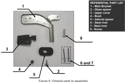
The Substituted Assembly
The original assembly composed of plastic parts and press worked (Figure 5) metal lead to nineteen attaching, two riveting and one screwing sequential operations. The assembly condition demanded two working positions
and needed specific equipment and care. Also, the attaching manipulation was fully manual and highly sensible to errors due to the complexity of joining all parts together in a high productive line. Thus, the riveting operation had its
flux. After all, the conditions to do the attachment of another metal part over a
glued curved tempered glass-metal part were an additional complexity.
1
2 3
5
6 and 7 4
REFERENTIAL PART LIST 1 – Main Bracket
2 – Glass spacer 3 –Uppercover 4 – Bush
5 – Internal spacer 6 – Steel rivet 7 -Steel rivet 8 -Screw
REFERENTIAL PART LIST
1 – Main Bracket 2 – Glass spacer 3 –Uppercover 4 – Bush
5 – Internal spacer 6 – Steel rivet 7 -Steel rivet 8 -Screw
8
Figure 5: Original parts to assembly.
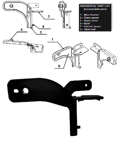
Avoiding these inconveniences, exposed in the previously, and to fit
the high level of reliability required, a new injected component was designed to aggregate in a single plastic construction the maximum of the original parts and an error free mounting. This component was conceived under the DFM/DFA and CE philosophy and it was expected to result in one high manufacturability development made from a productive low cost heavy duty material and designed to join six other components resulting in the maximum exclusion of intermediate operations.
partial anchorage and attached to the structure, ensuring the right placement of the whole assembly.
1 2
3
5 6
4
REFERENTIAL PART LIST
(Incorporated parts)
1 – Main Bracket 2 – Glass spacer 3 –Uppercover 4 – Bush
5 – Internal spacer 6 – Steel rivet
REFERENTIAL PART LIST
(Incorporated parts)
1 – Main Bracket 2 – Glass spacer 3 –Uppercover 4 – Bush
5 – Internal spacer 6 – Steel rivet
Figure 6: New part design.
cross-phased from the pivot and grooved to fit the construction of the column
where the part is mounted on which by its geometry reduce around zero the possibility of a wrong assembly. The bush (Figure 6, item 4) is also 90° cross-phased from the other two attachments, ensuring the full locking of the component to the environmental geometry, causing a full complete assembly, even when the other components (not treated by this development) present variations outside of the tolerance levels.
All that were presented and the extreme easiness to produce an
injected part results in 80% reduction in the assembly and 15% reduction
in the composition of costs, as well as a short term payback of the injection mould and will be discussed in the next section.
Discussion
This article has shown an application for the concepts of DFM/ DFA inserted in a Concurrent Engineering (CE) collaborative context for the development of a new part for the white goods industry (home appliances) focused in low-cost, high manufacturability, long-term reliability and resistance to severe working duty. The design of the part was based in the industry-level and literature review and demonstrated the application of the concepts and its advantages in the development of products with high manufacturability.
As previously justified, the development of a new part in any industry
(mainly in the analyzed case of the white goods industry) speeds up the whole process substantially when worked in a collaborative-concurrent engineering environment (when teams work together and simultaneously the results of the development can be faster and furthermore, cheaper). Using the Concurrent Engineering as the main guideline, in addition with DFM/DFA as methodology of work, results can be reached faster increasing the level of control, investment application and rightfulness. So that, the main objective for the industry and the cost reduction can be achieved successfully.
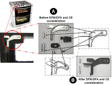
especially useful because they permitted a better communication between all involved teams. Also, these philosophies helped the product life cycle movement from Product Engineering to Production and Industrial Engineering. During this movement a parallel between design and manufacture were create allowing the development of tools (mould and assembly devices) and the shop
floor of manufacturing area. Figure 7 makes a comparison between 2 design considerations of the part: the detail “A” shows the initial configuration before DFM/DFA and CE; the detail “B” shows the final part designed according to
DFM/DFA and CE concepts.
The used concepts were decisively important because of the advantages of time saving through easier communication process. The mould was made as expected by the product developers, therefore the product could be manufactured correctly, avoiding rework. Despite the part had to be
designed several times, the final component was injected only once, saving
money in prototypes, tests and working time. The component was designed based in the production line (fewer parts and assembly-line speeders as fast locks, pins in place of rivets or screws, pre-assembled features, self-positioning parts and adaptable robust-design) in order to make the production teams more productive teams, saving money. The production of fewer parts has an impact of 15% over the whole assembly costs, directly in the materials price
with the advantage of improving logistics, the shop floor space and avoiding
the searching for different suppliers.
Finally, another advantage of the application of the DFM/DFA and CE
concepts in the design product development was the finding of a new way
Before DFM/DFA and CE consideration
After DFM/DFA and CE consideration
A
B
Figure 7 – Direct comparison between parts (copyright by Electrolux do Brasil S/A).
Table 2 – Direct comparison between achieved data.
ISSUE DESIGNORIGINAL DFA/DFM/CE DRIVEN DESIGN
Number of parts 8 3
Number of the operations
required 13 3
Attachments 3 2 (1, considering individuals)
Cost (proportion) 100% 30.21%
Time over assembly line 48 seconds 13 seconds
Conclusions
This research has explored DFM/DFA and CE concepts to create a synergy of different engineering group, working in an integrated environment, in order to create a component for a white good. The results of applying these
concepts were: i) a changing in the concept of how the teams should work; ii)
the substantial costs reduction in design and production development.
Regarding to the costs reduction, the applying of DFM/DFA allowed the design takes out the non-essential parts of the assembly, (Figure7),and
even though the time spent in this phase could be increased significantly, the design will be more elaborated and precise, bringing benefits for the next
phases of the product.
With the fewer steps and less necessity of people and machinery to run out, the production had a substantial cost reduction. An example of this was the direct substitution of several assemblies (several parts joined and
fixture) by only one injected part, moulded, die-pressed or casted. A similar
example was developed by Air Cargo-Lifters where the company reduced
99% of the number of individual fixing components.
There is more on the process of optimization by reducing the subassemblies, the process, most of the times, has more reliability, due to the elimination of fails directly by reducing the components that can offer
any type of low quality (considering that a fail probability is defined by a “n” in
hours in the M.T.B.F. or Mean Time Between Failures, is easy to consider that this number of probabilities rises when the number of parts increases) and giving conditions to do real accurate inspection on them, or simply eliminating by the design parts that can be incorrectly joined. The costs for stocking, transportation, supplier delays and others (direct or indirect) generated by
the number, complexity or even difficulty of production can be eliminated by
the optimization of the design using DFA/DFM and CE skills. Thus, there are several ways to reduce the cost by simply reviewing the design as Boothroyd
et al. (2002) and Boothroyd (2001) exposed “if you need to save, review your
design first”.
new equipment). A solution with high cost-effectiveness, low design-tooling-implementation time and high reliability was required, for these parameters a DFA/DFM/CE concept-driven component was welcomed.
The component was developed aiming cost reduction purposes. The difference between the past budget and the new one was not only based in component or raw material prices, but also connected to the price of the labor affected by the necessity of organize sub-assemblies, which has not only operational cost, but, also, investment on special machines, tools and equipment required to joint those assemblies. When comparing values of materials used before and after the DFM/DFA, the direct cost of materials (considered here only BOM component individual price) was reduced in 69.79%, with no quality or featuring restrictions. This change leads also to a manpower reduction – from three operators to only one. The assembly economy was 67%, as showed in Table 2, which brings some information, where more relevant data could be observed, mainly, the values of assembly cost and time.
The investment on a specific new tool (injection mould) for a 2-sided complete plastics part, only for the main component, was 10% lower than the necessity of a new die-pressing tool. Also, the new plastic part avoided the demand for a new high temperature stove (about US$ 150,000.00) that used to be used for a further process of glass-metal joining which required a special
adhesive, with a touch-time of thirty minutes under a specific temperature near
to 140°F, by using the resource of a complex three-dimensional geometry which could not be reached by die-pressing. In the Figure 7 it is possible to see the mentioned complex geometry and, also, the reduction of parts, the conditions that makes clear the assembly time reduction.
Acknowledgments
The authors want to thank the Electrolux do Brasil S/A. and the
Pontifical Catholic University of Paraná (PUC-PR) and all collaborators for
supporting this research.
References
pp. 345-358.
Anderson, D. M. (1990), “Design for Manufacturability; Optimizing
Cost, Quality, and Time to Market”, CIM Press, Lafayette, CA.
Beall, G. (1997), “The Dangers of Part Consolidation”, Available at: http://www.plasticstoday.com/imm/articles/dangers-part-consolidation, Last valid access in January 12th, 2009.
Boothroyd, G. (2001), “Product Design For Manufacture And Assembly, Second Edition”, Marcel Dekker Inc., New York, 374p.
Boothroyd, G. and Alting, L. (1992), “Design for Assembly and Disassembly”, Anais do CIRP, Vol. 41.
Boothroyd, G. and Dewhurst, P. E. (2008), “DFMA Helps Slash Warranty Costs and Boost Factory Floor Profits 600 Percent at Hypertherm”,
in http://www.dfma.com/news/hypertherm.htm, Last valid access in May 29th, 2008.
Boothroyd, G.; Dewhurst, P. E. and Knight, W. (2002), “Product Design for Manufacture and Assembly”, Marcel Dekker Inc, Nova York, 378p.
Bralla, J. G. (1986), “Handbook of product design for manufacturing”,
McGraw-Hill Inc., New York, NY, USA.
Brink, P. V. D. (2003), “Social Organizational and Technological Conditions that enable Knowledge Sharing”, Doctorate level Thesis in
Information Science, Fraunhofer FIT Hölderlinstr, Germany, 2003.
Buss, C. O.; Cunha, G. D. and Luce, F. B. (2001), “Coordenação de
equipes multidisciplinares no desenvolvimento de produtos”, XXI Encontro Nacional de Engenharia de Produção, Salvador, BA, Brazil (in Portuguese).
Canciglieri, O. and Young, R. I. M. (2003), “Information sharing in mutiviewpoint injection moulding design and manufacturing”, International
Journal of Production Research, England, Vol. 41, No. 7, pp.1565-1586.
Canciglieri-Jnr, O. (2005), “Design for Manufacture”, Curso de Especialização Lato Sensu em Engenharia da Produção da Universidade Católica do Paraná (PUCPR), Chapter 1. (in Portuguese).
Modelling and Advanced Design-for-the-Life-Cycle Systems: Feature Based
Product Life-Cycle Modelling, pp.109-128.
Capucho, M. J. O.; Da Silva, M. P. and Rubira, L. H. (2000),
“Engenharia simultânea e metodologia de projeto”, NuPES-Núcleo de pesquisa em engenharia simultânea, in: www.nupes.cefetpr.br, Last valid access in September 30th, 2000. (in Potuguese)
Dalgleish, G. F.; Jared, G. E. M. and Swift K. G. (2000), “Design and Assembly: influencing the design process”, Journal of Eng. Design, Vol. 11, No. 1, pp. 17-29.
Daré, G.; Ferreira, C. V.; Ogliari, A.; Back, N.; Beal, V.; Ribeiro A. S.
and Ahrens, C. H. (2001), “Aplicação da Engenharia Simultânea ao Processo de Desenvolvimento de Componentes Plásticos Moldados por Injeção: Um Estudo de Caso”, 3º Congresso Brasileiro de Gestão de Desenvolvimento de Produto, Florianópolis, SC, Brazil. (in Portuguese).
Fagade, A. and Kazmer, D. O. (2000), “Early Cost Estimation for Injection Moulded Components”, Journal of injection molding technology. Vol.
4, No. 8, pp. 97-106.
Farinha, F.; Jardim-Gonçalves, R. and Garção, A. S. (2007), “Integration
of cooperative production and distributed design in AEC”, Advances in
Engineering Software, Vol. 38, No. 11-12, pp. 772-779.
Ferneda, A. B. (1999), “Integração Metrologia, CAD e CAM: Uma Contribuição ao Estudo de Engenharia Reversa”, Master Degree Level Dissertation, UFSCar. (in Portuguese)
Ferreira, H. S. R. and Toledo, J. C. (2001), “Metodologias e Ferramentas de Suporte à Gestão do Processo de Desenvolvimento de Produto (PDP) na Indústria de Autopeças”, Proceedings of ENEGEP (Brazilian Meeting of Industrial Engineering). Available at: http://www.abepro.org.br/biblioteca/
ENEGEP2001_TR52_0820.pdf. Last valid access in January 10th, 2010. (in
Portuguese).
Galdámez, V., 2000. Integrando os Recursos Humanos com Engenharia Simultânea. Master Dissertation, Universidade de São Paulo (USP), São Paulo. (in Portuguese)
Gautier, B.; Dewhurst, P. and Japikse, D. (2000), “Application of
Products”, American Institute of Aeronautics and Astronautics.
Hartley, J. R. (1998), “Engenharia Simultânea: um método para reduzir
prazos, melhorar a qualidade e reduzir custos”, Artes Médicas, Porto Alegre, 266p. (in Portuguese)
Huang, G. Q. (1996), “Design for X”, Chapman and Hall, Great Britain,
488p.
Kotler, P. (2007), “Fala sobre inovação, fidelidade, segmentação,
sustentabilidade e customização”, Mundo do Marketing. Available at: http://
www.mundodomarketing. com.br/5,1780,philip-kotler-fala-sobre-inovacao-fidelidade-segmentacao-sustentabilidade-e-customizacao.htm, Last valid access in November 12th, 2009. (in Portuguese)
Kovalchuk, J. P. B. (2006), “Application of DFA in the development of white goods parts – a case study”, Master Dissertation, PPGEPS/PUCPR, Brazil.
Maniscalco, M.; Boothroyd, G. and Dewhurst, N., (1999), “When Molders Design, Success Follows”, in: <http://www.immnet.com/article_ printable.html ?article=2533>, Last valid access in May 14th, 2005.
Marshall, R. (1997), “The Holonic Product Design (HPD) - A Workbook”, Loughborough Univeristy, 35p.
PASMAN, G. (2003), “Designing with precedents”, Ph.D. Thesis (Industrial design). The Netherlands, TU Delft. 224 pages.
Rozenfeld, H.; Forcellini, F.; Amaral, D.; Toledo, J.; Silva, S.; Alliprandini,
D. and Scalice, R. (2006), “Gestão de Desenvolvimento de Produtos, uma referência para melhoria do processo”, Editora Saraiva, São Paulo, Brazil. (in Portuguese).
Sacchelli, C. M. (2005), “Proposta de Sistematização do processo de Desenvolvimento Integrado de Moldes de Injeção de Termoplásticos”, Doctorate Thesis Proposal, UFSC, SC, Brazil. (in Portuguese).
Sivaloganathan, S.; Andrews, P. J. T. and Shahin, T. M. M. (2001),
“Design function deployment: a tutorial introduction”, Journal of Eng. Design, Vol. 2, No. 1, pp. 59-74.
Industry, Vol. 57, No. 3, pp. 245-260.
Tellis, W. (1997), “Introduction to Case Study”, The Qualitative Report, Vol. 3, No. 2.
Wohnhas, S. (2003), “DFA Implementation in Whirlpool Europe: Experience and Results”, Design IV, Great Britain.
Yang, X. and Mcgreavy, C. (1996), “Requirements for sharing process data in the life cycle of process plants, Computers & Chemical Engineering,
Vol. 20, Supplement 1, pp. S363-S368.
Yin, R. and Moore, R. (2001), “Planejamento e métodos”, Bookman, Porto Alegre, 205 p. (in Portuguese)
Biography
Osiris Canciglieri Junior is graduated in Industrial Mechanic Engineering at School of Industrial Engineering of São José dos Campos-
SP - Brazil (1991); Master of Science degree in Mechanical Engineering at
State University of Campinas – SP - Brazil (1994) and Ph.D. in Manufacturing Automation at Loughborough University – Loughborough – UK (1999).
Postdoctoral research at Loughborough Univiversity in 2008. He is currently professor at the Pontifical Catholic University of Parana (PUC-PR). He has experience in Product Development and Production Engineering with emphasis on Production. Professor Canciglieri, research’s areas of interest are: Manufacturing Processes, Planning and Production Control, CAD/CAM, DFM, DFA, and Product Development in a Concurrent Engineering Environment. Contact: [email protected]
Antonio Batocchio is graduated in Civil Engineering at University of
São Paulo (1979); Master of Science degree in Mechanical Engineering at University of Sao Paulo (1987) and Doctoral in Mechanical Engineering at
and control, production management, supply chain, manufacturing systems, strategic management and quality tools.
Contact: [email protected]
João Pedro Buiarskey Kovalchukis graduated in Electrical Engineering
at Federal University of Parana - UFPR(1998); Master Science degree in Industrial Engineering and Systems by PPGEPS at Pontifical Catholic University
of Parana (PUC-PR) in 2006. Actually he is working in Active in Quality of Items Purchased at CNH Latin America. He has experience in Product Development and his research area of interest is Product Development in a Concurrent Engineering Environment.
Contact: [email protected] Article Info: