Computational Analysis of Heat Transfer by
Natural Convection from Triangular Notched Fin
Array
Sachin R. Pawar R. B. Yarasu
M. Tech. Scholar Associate Professor
Department of Mechanical Engineering Department of Mechanical Engineering Government College of Engineering,
Amravati – 444 604
[M.S.] India
Government College of Engineering,
Amravati – 444 604
[M.S.] India
Abstract
The purpose of this analysis is to find out the effect of making triangular notch at central base of fin on natural convection heat transfer. In case of horizontal fin arrays (L/H~5) [1], it is observed that the air entering from both the ends gets heated as it moves towards the centre of the fin channel, as well as it rises due to decrease in density. So, a stagnant zone is created at the central bottom portion of fin array channel and hence it does not contribute much in heat dissipation [1]. In this experimental investigation, material from this stagnant portion is removed in the shape of triangular notch from the central bottom portion of fin and added on top side to modify its geometry for analysis. The fin weight remains same. Three types of fin arrays have been analysed that are fin array with 0%, 20% and 40% notch. In this analysis heat input is varied from 50W to 200W in the interval of 50W analysis is done till steady state conditions. In this analysis decrease in heat transfer coefficient is observed for 20% and 40% notch fin than fin without notch.
Keywords: Fin Array, Natural Convection, Triangular notch, Single Chimney Flow, Notch Fin Array
________________________________________________________________________________________________________
I.
I
NTRODUCTIONNow days we want compact devices which makes overheating problem possibility more, because of reduction in surface area available for Heat Transfer. So Optimization of fin heat transfer area and geometry becomes very important.
II.
N
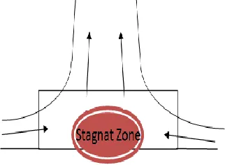
EED OF INVESTIGATIONGenerally in natural convection heat transfer with vertical fin array on horizontal fin base, it is observed that single chimney flow pattern as shown in fig. 1 is observed. In single chimney flow pattern, there is sideway entry of the air in case of natural convection cooling of fin array. So the air coming inwards gets heated as it moves towards the center of the fin [9] and this heated air it rises up due to decrease in density.
Fig. 1: Single Chimney Flow Pattern
Area Compensation Method: A.
Fig. 2: Area Compensation Method with Triangular Notch
In this investigation, the fin flats were modified by removing the central fin portion by cutting a notch of triangular shapes and adding it at the top of fin surfaces, where it may be more effective and thereby keeping fin surface area same with height increases. Experimental analysis is done for three types of arrays mainly Fin array without Notch, Fin with 20 % (notch) area removed and compensated, Fin with 40 % (notch) area removed and compensated.
III.
C
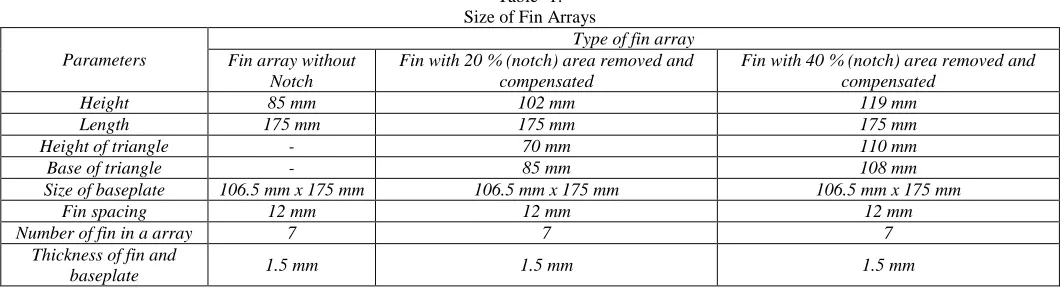
OMPUTAIONAL ANALYSISSize of Fin Arrays: A.
Table -1: Size of Fin Arrays
Parameters
Type of fin array Fin array without
Notch
Fin with 20 % (notch) area removed and compensated
Fin with 40 % (notch) area removed and compensated
Height 85 mm 102 mm 119 mm
Length 175 mm 175 mm 175 mm
Height of triangle - 70 mm 110 mm
Base of triangle - 85 mm 108 mm
Size of baseplate 106.5 mm x 175 mm 106.5 mm x 175 mm 106.5 mm x 175 mm
Fin spacing 12 mm 12 mm 12 mm
Number of fin in a array 7 7 7
Thickness of fin and
baseplate 1.5 mm 1.5 mm 1.5 mm
Description: B.
Computational fluid dynamic, results are very close to the experimental results obtained. Ansys Fluent-14 software is used for Computational fluid dynamic analysis. The fin surfaces, with base are assumed as a source, held at uniform temperature. Laminar natural convection is the mechanism for heat transfer from the fin array. Radiation heat loss is not considered here.Geometry creation and meshing is done in ANSYS-Workbench. The 3D geometric model of fin without notch and notch fin array is created. Figure showing the 3D geometry model which is created in ANSYS Workbench consisting the fin array assembly and enclosure for natural convection condition.
Top surfaces is assigned pressure inlet where air enters and all the remaining boundaries are assigned as pressure outlet where air leaves the channel at the ambient temperature T∞. Here the ambient pressure is used as stagnation boundary condition with the incoming mass having the ambient temperature. The static pressure is assumed equal to the pressure of surrounding atmosphere. For seeing results and plots CFD-POST is used [11]. Fromgraphics and animation, contours of temperature at various surfaces are viewed. In this work the temperature distribution profile on the fin is obtained which was used to calculate the heat transfer coefficient using formulaes.
Contours for all fin array set up is captured for [11] various heat flux like 10732 W/m2, 8050 W/m2, 5366 W/m2and 2683 W/m2, which are equivalent to 50 w, 100 w, 150 w, and 200 w respectively.
Temperature Contours: C.
Fig. 3: Temperature Contour for Fin without Notch at 100 Watt
Fig. 4: Temperature Contour for 20 % Notch Fig. 5: Temperature Contour for 40 % Notch Fin at 100 Watt Fin at 100 Watt
Velocity Contours: D.
Here velocity contours of all types of fin are shown. It is seen that single chimney flow pattern is maintained for notch as well as without notch fin.
Fig. 6: Velocity Contours for Fin without Notch and Fin with 20% and 40% Notch
IV.
P
ROCEDURE FOR CALCULATIONThe formulae that are used for calculating heat transfer coefficient are taken from book
,
“Heat Transfer’’ by J. P. HolmanTo Find Average Temperature of Fins (Tf ): 1)
Tf =
Where, T1, T2, T3, T4, T5, T6 and T7 are the temperatures of tip of fins in ° C.
To Find Temperature of Whole Body (Tbody): 2)
Tbody =
Where, Tb are the temperatures of base plate in °C
To Find Temperature Difference Between Body (Tbody ) & surrounding temperature (Tsurr): 3)
To Find Mean Film Temperature (Tm): 4)
Tm =
°C From this temperature find out following properties of fluid
υ = kinematic viscosity of the fluid, m2 /s Pr = Prandtl number
k = thermal conductivity of fluid, W/mk
To Find Coefficient of Volume Expansion (β):
5)
β = k-1
To Find Grashof Number (Gr):
6)
Gr =
Where,
Lc= height of the fin, m
To Find Rayleigh Number (Ra): 7)
Ra = Gr*Pr If 104< Gr*Pr< 109, then, Nu = 0.59 (Gr*Pr)1/4
If 109< Gr*Pr< 10 12
, then, Nu = 0.59 (Gr*Pr) 1/3
To Find Heat Transfer Coefficient (h):
8)
Nu =
Where, h is heat transfer coefficient, W/m2k Using these formulae h is calculated.
V.
R
ESULTAfter performing calculations, results were tabulated and a comparison was made also graphs was obtained, which clearly shows effect of notch made in this way with thisdimensions on heat transfer coefficient.
Table -1:
Results of Computational Analysis at different heat input
Heat Input, Q (watts)
Heat transfer coefficient h in W/m2k Fin without
notch
Fin with 20% (Notch) area removed and compensated
Fin with 40 % (Notch) area removed and compensated
50 6.6982 6.22 6.006
100 7.4215 7.05185 6.969
150 7.894 7.5758 7.493
200 8.22 7.933 7.84
Based on these results different graphs are plotted, which are given and discussed below.
Variation of Heat Transfer Coefficient (h) for Computational Analysis: A.
Fig. 6: Variation of H with Heat Input for Different Fin Arrays Based on Computational Result.
for notched fin is less than without notch fin. There is approximately 8.41 % reduction in heat transfer coefficient for 20 % notch fin over fin without notch. There is approximately 10.7 % reduction in heat transfer coefficient for 40 % notch fin over fin without notch.
VI.
C
ONCLUSIONComputation alanalysis is done three types of arrays mainly fin array Fin without Notch, FIN with 20 % (notch) area removed and compensated, FIN with 40% (notch) area removed and compensated. I have used this area compensation method by removing material from center in the form of triangular notch and adding at top of fins. The conclusions were drawn from this analysis are given below.
1) Heat transfer coefficient is lower in notched fin array compared to without notch fin array.
2) There is approximately 7 % reduction in heat transfer coefficient for 20 % notch fin over fin without notch.
3) There is approximately 10 % reduction in heat transfer coefficient for 40 % notch fin over fin without notch. Means with increase in notch heat transfer coefficient goes on reducing.So making notch in this way is not effective method for increasing heat transfer.
4) With increase in heat input, heat transfer coefficient (h) also increases for all types of fin arrays whether it is notched or without notch fin array which pattern matches with the pattern of all researchers.
5) Single chimney flow pattern is maintained in all three types of fin arrays.
ACKNOWLEDGEMENT
I would like to express my sincere gratitude to Dr. R. B. Yarasu, Asso. Professor, GCOEA, for his constant support, valuable guidance and encouragement throughout the course work for completing this work.
REFERENCE
[1] S. D. Suryawanshi and N K Sane, Natural Convection Heat Transfer from Horizontal Rectangular Inverted Notched Fin Arrays, ASME J. Heat Transfer, vol. 131, (2009), 082501-082506
[2] Umesh V. Awasarmol and Ashok T. Pise, An Experimental Investigation of Natural Convection Heat Transfer Enhancement from Perforated Rectangular Fins Array at different Inclinations, Experimental Thermal and Fluid Science, ELSEVIER, 2015, S0894-1777(15)00108-9.
[3] Juan Li, Xiang Ling Hao Peng ,Field synergy analysis on convective heat transfer and fluid flow of a novel triangular perforated fin, International Journal of Heat and Mass Transfer, 64, (2013),pp. 526–535.
[4] Shaeri and Yaghoubi , Energy Conversion and Management, Volume 64, science direct,December 2012, Pages 328-334.
[5] Md. Farhad Ismail, M.O. Reza, M.A. Zobaer, Mohammad Ali, Numerical investigation of turbulent heat convection from solid and longitudinally perforated rectangular fins, 5th BSME International Conference on Thermal Engineering, Procedia Engineering 56, 2013, pp. 497–502.
[6] Baskaya, S, Sivrioglu, M, and Ozek, M, “Parametric Study of Natural Convection Heat Transfer from Horizontal Rectangular Fin Arrays,” International Journal of Thermal Science, 39, 2000, pp. 797–805.
[7] M. Dogan, M. Sivrioglu, Experimental investigation of mixed convection heat transfer from longitudinal fins in a horizontal rectangular channel, International Journal of Heat and Mass Transfer, ELSEVIER, 2010, pp. 2149–2158.
[8] S. D. Wankhede, C. B. Meshram , Experimental Study and Investigation of Heat Transfer from Horizontal Rectangular Inverted Notch Fin Arrays (INFAS) Under Natural and Forced Convections, International Journal of Researchers, Scientists and Developers (IJRSD) Vol. 2 No. 1 January 2014 ISSN: 2347-3649.
[9] S. R. Dixit, Dr. D. P. Mishra, Dr. T. C. Panda ,Experimental analysis of heat transfer and Average heat transfer coefficient through fin Array with or without notch using free Convection, International Journal of Advance Research, IJOAR Volume 1, Issue 2, MAY 2013, Online: ISSN 2320-9186. [10] Salila Ranjan Dixit, Dr. Tarinicharana Panda ,Numerical Analysis of Inverted Notched Fin Array Using Natural Convection, IOSR Journal of Mechanical
and Civil Engineering (IOSR-JMCE) e-ISSN: 2278-1684, p-ISSN: 2320-334X, Volume 6, Issue 4 (May. - Jun. 2013), PP 47-56.
[11] S. M. Wange, R. M. Metkar ,Computational Analysis of Inverted Notched Fin Arrays Dissipating Heat by Natural Convection, International Journal of Engineering and Innovative Technology (IJEIT) Volume 2, Issue 11, May 2013.
[12] S. S. Sane, N. K. Sane, G.V. Parishwad , Computational analysis of horizontal rectangular notched fin arrays dissipating heat by natural convection, 5th European Thermal-Sciences Conference, The Netherlands, 2008.
[13] Shivdas S. Kharche, Hemant S. Farkade , Heat Transfer Analysis through Fin Array by Using Natural Convection, International Journal of Emerging Technology and Advanced Engineering (IJETAE) (ISSN 2250-2459, Volume 2, Issue 4, April 2012).
[14] S. H. Barhatte, M. R. Chopade , Experimental and Computational Analysis and Optimization for Heat Transfer through Fins with Triangular Notch, International Journal of Emerging Technology and Advanced Engineering ( IJETAE ) ISSN 2250-2459, Volume 2, Issue 7, July 2012.
[15] J. P. Holman, “Heat Transfer”, Tenth Edition, Tata Mc Graw Hill, 2010, pp.327-339.