(UDC: 692.535.6:519.673)
Finite Element Modeling and Analytical Simulation of circular GLARE
fiber-metal laminates subjected to lateral indentation
G. J. Tsamasphyros1 and G. S. Bikakis1*
1National Technical University of Athens, Strength of Materials Laboratory, 9 Iroon
Polytechniou, Zographou, GR 157 73, Athens, Greece [email protected]
*Corresponding author
Abstract
GLARE is a Fiber-Metal Laminated material used in aerospace structures which are frequently subjected to various impact damages. Hence, response of GLARE plates subjected to lateral indentation is very important. No FEM or other analytical solution of this problem is known to the authors.
This paper deals with the static response of thin circular clamped GLARE plates under the action of a lateral hemispherical indentor located at their center. We propose a finite element modeling procedure for the calculation of static load-indentation curve and the first failure load and
geo
2-2/1-0.3 plate with a radius of 40 mm. Both numerical and analytical load-indentation curves and first failures agree well with the experimental values (failure load within
ection within 5% and 3% respectively).
It is sh that our analytical results converge satisfactorily. Also, the expected governing deflection due to glass-epoxy tensile fracture applicable to GLARE plates. Additionally, we further verify the validity of the analytical model for the solution of this problem which we have derived using the Ritz method in our previous work.
A 3-D solid modeling procedure with ANSYS is implemented. We employ an isotropic non-linear elastoplastic material model which obeys a true stress-strain relation for aluminum. An orthotropic linear elastic material model is used for the glass-epoxy. The contact between the indentor and the plate is simulated by contact elements. We use non-linear analysis with
metric and material non-linearities. The indentor is forced to move and deform the plate incrementally. Analysis stops when first failure due to glass-epoxy tensile fracture occurs. This FEM procedure and our analytical model are applied to GLARE 2-2/1-0.3 and to GLARE 3-3/2-0.4 plates with various diameters.
We compare FEM results with analytical results and their good agreement is demonstrated. Furthermore, FEM and analytical results are compared with published experimental data for the case of a GLARE
2% and 7%, failure defl own
role of the membrane in comparison with the bending stiffness is demonstrated. Finally, FEM plots of lateral GLARE plate deflections justify the axisymmetrical deflection shape considered by the authors.
1. Introduction
This paper focuses on the response of thin circular clamped GLARE fiber-metal laminated plates which are subjected to lateral indentation. Among other applications, GLARE is mainly used in aerospace structures and has higher impact resistance in comparison with conventional composites or aluminum alloys (Vogelesang and Vlot 2000, Vermeeren 2003).
Impact properties are very important in aerospace structures, since impact damage is caused by various sources, such as maintenance damage from dropped tools, collision between service cars or cargo and the structure, bird strikes and hail (Vogelesang and Vlot 2000, Vermeeren 2003, Vlot 1996, Vlot 1993, Laliberte et al. 2002). A large amount of the energy absorbed by GLARE plates during low velocity, high velocity or even ballistic impacts is due to the static deformation of the plate (Vlot 1996, Hoo Fat et al. 2003, Lin and Hoo Fat 2006). In this regard, the response of GLARE plates subjected to lateral indentation is very important as far as their overall impact behavior is concerned.
In this work we deal with the static response of thin circular clamped GLARE fiber-metal laminated plates under the action of a lateral hemispherical indentor located at the center of the plate. Vlot (1996) used an elastic-plastic impact model to solve this problem numerically assuming a deformation profile based on experimental data. Hoo Fatt et al. (2003) used the principle of minimum potential energy to model analytically the response of fully clamped square GLARE panels assuming a deformation profile which resembles that of a stretched membrane. They also calculated the first failure load due to glass-epoxy tensile fracture. In our
previous work ( corresponding
to one, two and tion of lateral
indentation response applicable to thin circular GLARE plates.
s paper is to develop a finite element modeling procedure for the calculation of static load-indentation curve and the first failure load and deflection due to
glass-pplication to GLARE 2-2/1-0.3 and to GLARE 3-3/2-0.4 circular plates with various
ults and the final
ly by an indentor with a hemispherical tip of radius R acting at the
2008), we employed the Ritz method and derived formulas three-parameter approximation functions for the calcula
The first objective of thi
epoxy tensile fracture of thin circular clamped GLARE fiber-metal laminated plates under the action of a lateral hemispherical indentor located at their center. The ANSYS finite element program is used for this purpose. The second objective is to verify the validity of our analytical model (2008) by a
diameters and by comparison of analytical results with the corresponding FEM results. We compare numerical results with analytical results and their good agreement is demonstrated. Furthermore, FEM and analytical results agree well with published experimental data for the case of a GLARE 2-2/1-0.3 plate with a radius of 40 mm (Vlot 1996). No FEM or other analytical solution of this problem is known to the authors.
In the following sections the definition of the problem is first given, then details of the FEM modeling and analytical simulation are presented followed by the obtained res
conclusions.
2. Problem definition
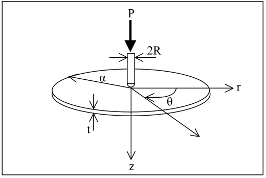
We consider a thin clamped circular GLARE plate with radius α and thickness t as shown in Fig. 1. The plate is loaded statical
center. The plate consists of alternating layers of aluminum and glass-epoxy. The aspect ratio α/t is assumed very high so that shear deformation and local indentation are negligible.
boundary. As the indentor progresses the load P applied on the plate and the corresponding central deflection wo increase. The (P , wo) curve and the first failure load and deflection due to
glass-epoxy tensile fracture will be calculated analytically and numerically using ANSYS.
P
2R
r
θ
z
α
t
Fig. 1. Circular plate problem geometry and coordinate system
3. Finite element modeling
In this paper we implement a finite element modeling procedure to predict the static response of thin circular clamped GLARE fiber-metal laminated plates under the action of a lateral hemispherical indentor located at the center of the plate. ANSYS finite element program is used for this purpose.
The GLARE plate is modeled with two solid elements of different type along its thickness. The external aluminum layer, which is in contact with the indentor, is modeled with SOLID 185 elements. These hexahedral-shaped elements have eight nodes with three translational degrees of freedom per node. In order to reduce the computational cost, the remaining layers of the GLARE plate are modeled with SOLSH 190 elements. These are also hexahedral-shaped layered elements with eight nodes and three translational degrees of freedom per node. The accuracy of the
The indentor is also modeled with SOLID 185 elements. In order to simulate the contact betw
linear elastic material model with increased stiffness. We idealize the material behavior of the GLARE plate unidirectional glass-epoxy layers by employing an orthotropic linear elastic material model. The material of the GLARE plate 2024-T3 aluminum layers is modeled with an
se elements is governed by the first order shear deformation theory.
een the indentor and the external surface of the GLARE plate, we use CONTA 174 and TARGE 170 elements in way of the contact areas. The plate is clamped along its boundary. Due to symmetry of the problem we further reduce the computational cost by modeling only one quarter of the structure. Suitable symmetry boundary conditions are applied in this regard to all nodes of the symmetry planes.
isotropic non-linear elastoplastic material model which obeys the following true stress-strain relation (Chandrakanth and Pandey 1998):
n
1
(1)where σΟ is the yield stress of 2024-T3 aluminum, κ= 650 and n = 1.62.
A static non-linear analysis is employed with geometric and material non-linearities. The indentor is forced to move and deform the GLARE plate incrementally. Our analysis stops when the first failure due to glass-epoxy tensile fracture occurs. The maximum tensile strain criterion is used in order to verify when first failure occurs. The corresponding indentor’s position and load are then recorded as the first failure deflection and load.
In order to verify the convergence of FEM results, (P , wo) curve and the first failure load
and deflection due to glass-epoxy tensile fracture, we built three models with increasing plate mesh density for each specific case of circular GLARE plate we analyze. A fine mesh is used for the indentor in order to represent its geometry accurately. The indentor’s mesh density remains the same for all models. A typical fine mesh of a GLARE plate along with the indentor is depicted in Fig. 2.
Fig. 2. Finite element mesh of a GLARE 2 plate with the indentor
We apply this finite element modeling procedure to GLARE 2-2/1-0.3 circular plates with 5 mm, 40 mm and 45 mm radius and to GLARE 3-3 0.4 circular plates with 65 mm, 70 mm and 75 mm radius. A total of eighteen finite element models have been implemented. The
erical results are compared with the corresponding xperimental data for the case of a GLARE 2-2/1-0.3 pla
3
/2-num analytical results and published
4. A
e-arameter Ritz approximations of th rofile for the calculation of s
ntation curve and first failu ion due to glass-epoxy tensil pplicable to thin circular clamped GLARE fiber-metal laminated plates under the a teral hemispherical indentor located at their center. Two cases of plate stiff
ed. Firstly, due to very large deflections, the bending resistance is neglected and only brane resistance of the plate is taken into account. In the second case, both bending and embrane resistance are taken into account. The derived fo ulas were applied to a GLARE 2-2/1-0.3 plate with 40 mm radius. In this work, in order to verify the validity of our analytical
lution, we apply the derived formulas to GLARE 2-2/1-0.3
mm radius and to GLARE 3-3/2-0.4 circular plates with 65 mm, 70 mm and 75 mm radius. The nalytical results are compared with the corresponding FE results and available published experimental data for the case of a GLARE 2-2/1-0.3 plate with a radius of 40 mm (Vlot 1996).
the following paragraph a short presentation of the analytical eq
circular GLARE plate indentation problem is given from Tsamasphyros and Bikakis (2008).
.1 Analytical equations
For o ate resistance, the
den
nalytical simulationWe previously derived (2008) analytical formulas corresponding to one, two and thre
p tatic
load-inde re load and deflecte deformation p e fracture
a ction of a
la ness were
consider the mem
m rm
so circular plates with 35 mm and 45
a M
In uations for the solution of the
4
ne Ritz parameter, considering both bending and membrane pl tation load is directly calculated by the following equation:
in
Mxy
P o 4
o xy y x w A A A A w N N
N 0.734 0.62 0.412 2
576 . 0 2 3 66 12 22 11
58 3.876ln
66
o2w D
(2)
12 22
11 8.124 1.938ln 14.7
ln 906 . 2 318 .
3 D D D
x, Ny and Nxy are the in-plane forces of the aluminum layers calculated as follows:
Al y
x N m t
N N , Al o
xy m t
N
3
here m is the number of aluminum layers and tAl is the thickness of
(3)
w each aluminum layer.
Aij and Dij are the extensional and bending stiffnesses of the laminate. Mxy is the twisting
moment acting on the aluminum layers calculated as follows (for m1 or m2,4,... or ,.
5 , 3
m .. respectively in equation 4):
3 4 2 Al xy t M ,
m i i Al xy Z t M 1 3 , 3 4 3 2 1 1 Al m i i Al xy t Z tM
here Zi is the geometric distance of each aluminum layer from the neutral surface of the plate.
For one Ritz parameter, considering only the membrane plate resistance, P is c from equation (2) where Mxy and all Dij terms are now equal to zero.
(4)
w
For two Ritz parameters, considering both bending and membrane plate re ance, the solution of the following (2x2) non-linear system of algebraic equations yields the unknown
itz coefficients λ1 and λ2 for specific values of load P (wo is obtained by adding λ1 and
2 2
1 4 2 2 1 3 3 2 5 3 1 1 2 3 1
1 N 4M M 2M 3M
N 4 2 1 1 3 2
sist
R λ2 ):
2
P Mxy C C (5)
2 2
1 3 2 2 1 5 3 2 2 3 1 4 2 2 1
3 2N M 4M 3 2M N
P 4Mxy2C2
here:
xy y
x N N
N
N1 0.288( )0.367
M 2C31 (6)
w
,
xy y
x N N
N
N2 11.916( )15.171
xy y
x N N
N
N3 0.218( )0.278
(7)
,
11 22 12 66
21 1 2 103 . 0 ) ( 155 . 0 A A A A
M (8
) 2 66 12 22 11 2 1 2 056 . 137 ) ( 585 . 205 A A A AM (9
) 2 66 12 22 11 3 1 2 966 . 12 ) ( 449 .19 A A A A
M (10)
11 22 12 66
24 1 2 807 . 0 ) ( 211 . 1 A A A A
M ,
11 22 12 66
2 5 1 2 356 . 5 ) ( 033 . 8 A A A AM (11)
11 22
66
21 1 ln 938 . 1 379 . 7 . 4 ( ln 453 . 1 659 .
1 D D 062 0.969ln ) 12 D
C (12)
D
2 66 22
11
2 1114.758 36.335ln (613.985 (1615.549 48.447ln )
1 12 ) ln 224 . 24
D D D
C (13)
D 2 66 12 22 11 3 1 908 826 . 5 D D DC
For two Ritz parameters, considering only the membrane plate resistance, the unknown Ritz efficients are calculated from equations (5) and (6) where Mxy
For three Ritz parameters, considering d membrane pl lution of the following (3x3) non-linear s braic equation
Ritz coefficients λ1, λ2 and λ3 for specific val (wo is obtained by adding λ1 , λ2 and
): 2 2 1 4 2 2 1 3 3 1 1 3 6 2 3 1
1 4 3
2N N N M M
P (14) . 43 56 . 55 D
co and all Ci terms are now equal
to zero.
both bending an ystem of alge ues of load P
ate resistance, the
so s yields the unknown
λ3 3 3 11 3 2
5 M 2M
M 3 6 2 3 1 1 3 2 1 14 3 2 2
2 2
1 3 2 2 1 13 2 3 2 15 3 2 1 12 2 3 1
7 3 2 4 2
2M M M M M Mxy C C C
(15)
N 2
P 34M 3 M 33M
5
3 2
N M M
N 3 5 2 2 1 3 3 2 1 13 3 2 2 9 2 3 2 8 3 2 1 14 2 3 1
15 M 2M 3M 2M 4M C 2C C
M xy
(16)
2 2
1 14 2
3 13 2
3 6 3 2 9 3 1 12 3 4 2 5 1
6 N 2N M M M
N P 3 4 2 5 1 6 3 2 1
4M M
2 1 15 3 2 2 2
2 2 3 2 2 4 2
3M M M M M MxyC C C
11 1 3 7 1 3 10 2 3 8 (17)
where:
xy y
x N N
N
N439.046( )49.715 , N5 0.361(NxNy)0.459Nxy (18)
xy y
x N N
N
N6 0.141( )0.18 ,
2 66 12 22 11 6 1 2 737 . 1460 ) ( 104 . 2191 A A A A
M (19)
11 22 12
7 64.237(A A ) 42.825 A
M 66 2
1 2A
(20)
12 66
21 2
A A
M (21)
22 11
8 2665.467(A A )1776.976
2 66
1 2
A (22)
12 22
11
9 35.223(A A ) 23.482 A
M
11 22 12 66
210 1 2 678 . 30 ) ( 016 . 46 A A A A
M (23)
11 22 12 66
211 1 2 118 . 11 ) ( 677 . 16 A A A A
M (24)
11 22 12 66
2 12 1 2 252 . 0 ) ( 378 . 0 A A A AM (25)
66
21 2A
(26)
12 22
11
13 168.625(A A )112.416 A
M
12 66
21 2 835
. A A
22 11
14 28.253(A A
M )18 (27)
12 66
21 2 921 . A A 22 11
15 55.382(A A
M )36 (28)
4 11744.949 117.727ln D
C 11 D22 (7411.381 78.485ln)D12
7ln
D66
2 (21 9 . 6 9)
15 518 . 16078 2 66 12 22 11 5 29.824D D 484.976
C 30)
1 329 . 425 DD (
2 66 12
22 11
6 12.788D D 101.545D 75.967D
C 1 (31)
For the unknown Ritz
Ci terms are
three Ritz parameters, considering only the membrane plate resistance, coefficients are calculated from equations (15), 6) and (17) where Mxy and all
now
(1 equal to zero.
i
j
crit j j
1
2 2 3
4
, i1,2,3,... (32)
whereεcrit is the tensile failure strain of the glass-epoxy.
Depending on the number of Ritz parameters, an rane only
propriate set of d considering the case of memb
ne resistance, we use the ap resistance or the case of both bending and membra
the aforementioned equations. We start increasing the indentation load P, until the corresponding values of λj satisfy condition (32). When this happens, the indentation load P has
reached the critical value Pcrit and the corresponding first failure displacement wocrit is then
calculated, for those λj values, from the following equation:
i j
j o
w
1
, i1,2,3,... (33)
5. Results
We have applied the propose ytical formulas to
GLARE 2-2/1-0.3 plat 1-0.3 fiber-metal
laminate consists of two exte ass UD fiber prepregs
in the middle. Each alum reg has a thickness
of 0.1 mm. Prepregs hav ular GLARE 2 plates
with 35 mm, 40 mm and r our calculations
are given in Table 1. All av have been used. For
2024-T3 aluminum we have (Alderliesten 2005).
Remaining material prope 003) or have been
calculated based on
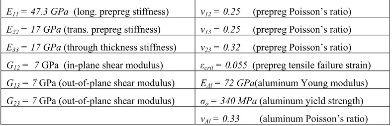
E11 = 47.3 GPa (long. pre isson’s ratio)
d finite element modeling procedure and the anal es and to GLARE 3-3/2-0.4 plates. GLARE 2-2/
rnal 2024-T3 aluminum layers and two R-gl inum layer has a thickness of 0.3mm and each prep
e the same orientation. We have analyzed circ 45 mm radius. The material properties considered fo
ailable properties of reference (Vlot 1996) considered a Poisson’s ratio equal to 0.33 rties have been taken from Hoo Fat et al. (2 the reciprocal relations.
preg stiffness) ν12 = 0.25 (prepreg Po
E22 = 17 GPa (trans. prepreg stiffness) ν13 = 0.25 (prepreg Poisson’s ratio)
E33 = 17 GPa (through thickness stiffness) ν23 = 0.32 (prepreg Poisson’s ratio)
G12 = 7 GPa (in-plane shear modulus) εcrit = 0.055 (prepreg tensile failure strain)
G13 = 7 GPa (out-of-plane shear modulus) EAl = 72 GPa(aluminum Young modulus)
G23 = 7 GPa (out-of-plane shear modulus) σο = 340 ΜPa (aluminum yield strength) ratio) νAl = 0.33 (aluminum Poisson’s
Table 1. GLARE 2-2/1-0.3 material properties
GLARE 3-3/2-0.4 fiber
[2024-T3 / 00 glass / 90 glass / 2024-T3 / 90 glass / 0 glass / 2024-T3]
Each 2024-T3 aluminum layer has a thickness of 0.4 mm. Each prepreg ply has a thickness of 0.125 mm and consists of S2-glass UD fiber prepregs. We have analyzed circular GLARE 3 plates with 65 mm, 70 mm and 75 mm radius. The material properties considered for our
-metal laminate consists of the following lay-up:
calculations are those εcrit which, according to our correspondence
with the manufactur .
The finite elem n results are presented and
compared in the following paragraphs.
5.1 Finite element modeling results
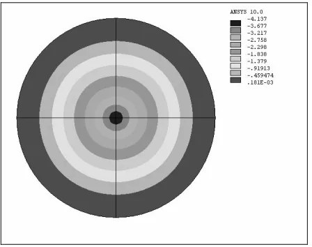
In Fig. 3 the lateral deflections of a GLARE 2-2/1-0.3 circular plate under the action of the indentor are illustrated. This is a representative deflection plot for the two different GLARE grades we examine. An axisymmetrical deflection shape can be observed. This observation further enhances Vlot’s experimental results (1996) concerning the axisymmetrical deflection shape of GLARE plates, whic onsidered by Vlot for his elastic - plastic impact model. It is noted that we ha ymmetrical deflection shape for our analytical simulation (2008). In Fig. 4 a repr ed shape of a GLARE plate is depicted. For these plots we have used ANSYS symmetry expansion command in order to
obtain results co of the structure.
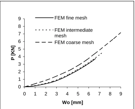
In Fig. 5 the stat adius of 40 mm
are depicted.
given in Table 1, apart from er of GLARE 3, is equal to 0.047
ent modeling results and analytical simulatio
h has been c
ve also considered an axis esentative deform
rresponding to a full model, since we have modeled a quarter ic (P , wo) curves of a circular GLARE 2-2/1-0.3 plate with a r
Fig. 4. Deformed shape of GLARE 2 plate with 40 mm radius
0 1 2 3 4 5 6 7 8 9
0 1 2 3 4 5 6 7 8 9
Wo [mm]
P
[KN]
FEM fine mesh
FEM intermediate mesh
FEM coarse mesh
Fig. 5. Load-indentation curves for GLARE 2 plate with 40 mm radius
o cted
curves stop at the point of the predicted first failure. It can be seen that the results converge satis
5.2
o nergy of circular
GLARE 2-2/1-0.3 plate with a radius of 40 mm are depicted. In Fig. 7 the static (P , wo) curves
the same GLARE 2 plate are Apart from the (P , w) curve which corresponds to the coarse mesh, all other depi
factorily. Similar behavior has been found in the cases of GLARE 2-2/1-0.3 plates with 35 mm, 45 mm radius and GLARE 3-3/2-0.4 plates with 65 mm, 70 mm, 75 mm radius.
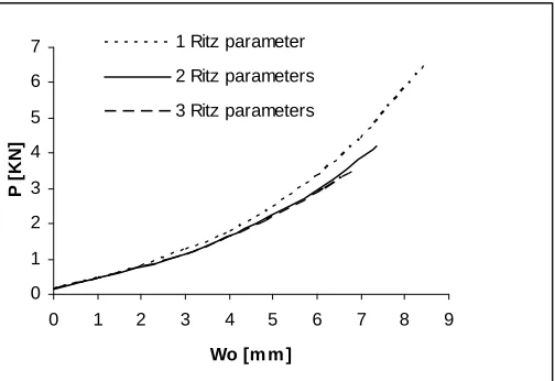
Analytical simulation results
In Fig. 6 the static (P , w) curves corresponding to the membrane strain e
corresponding to both bending and membrane strain energy of depicted.
0 1 2 3 4 5
0 1 2 3 4 5 6 7 8 9
P [
K
N
]
Wo [m m ] 1 Ritz parameter
2 Ritz parameters 6
7
3 Ritz parameters
Fig. 6. Membrane Load-indentation curves for GLARE 2 plate with 40 mm radius
0 1 2 3 4 5 6 7
0 1 2 3 4 5 6 7 8 9
1 Ritz parameter
2 Ritz parameters
3 Ritz parameters
P [
K
N
]
Wo [m m ]
brane & Bending Load-indentation curves, GLARE 2 plate, 40 mm radius
mm, 75 mm radius.
FEM (P , wo) curve. A good agreement between numerical and analytical results is
Fig. 7. Mem
It is noted that the rigid-perfectly plastic assumption for the aluminum yields the existence of constant bending terms in (P , wo) expressions. Due to these terms the plate does not deflect
until the load reaches a finite value that causes plastic flow. This is clearly illustrated in Fig. 7. Similar behavior has been found in the cases of GLARE 2-2/1-0.3 plates with 35 mm, 45 mm radius and GLARE 3-3/2-0.4 plates with 65 mm, 70
5.3 Comparison of FEM, analytical and experimental results
In Fig. 8 the static three - parameter (P , wo) curves corresponding to the membrane strain
dem
d of 3.
failure defl
onstrated. The expected (Tsamasphyros and Bikakis 2008) small contribution of bending stiffness in comparison with the membrane stiffness to the response of the GLARE plates can be observed from the analytical curves. A good agreement between numerical and analytical results and the small contribution of bending stiffness in comparison with the membrane stiffness has also been found in the cases of GLARE 2-2/1-0.3 plates with 35 mm, 45 mm radius and GLARE 3-3/2-0.4 plates with 65 mm, 70 mm, 75 mm radius.
Furthermore, both numerical and analytical results are compared with the experimental (P , wo) curve published by Vlot (1996) for the case of a GLARE 2-2/1-0.3 circular plate with a
radius of 40 mm. A good agreement between calculations and experimental data is found. The best numerical prediction, corresponding to the fine mesh FEM results, yields a first failure loa
75 KN and a first failure deflection of 6.65 mm which are within 2% and within 5% of the corresponding experimental values (3.8 KN and 7mm). The best analytical prediction, corresponding to the three - parameter Ritz approximation that takes into account both bending and membrane stiffness of the plate, yields a first failure load of 3.57 KN and a first
ection of 6.85 mm which are within 7% and within 3% of the corresponding experimental values.
Experiment
3 Ritz parameters membrane & bending FEM fine mesh 5
6 7
0 1 2 3 4
P
[KN]
3 Ritz parameters membrane
0 1 2 3 4 5 6 7 8
Wo [mm]
Fig. 8. Experimental vs. calculated Load-indentation curves, GLARE 2 plate, 40 mm radius
6. Conclusions
we have developed a finite element modeling procedure for the prediction of the static load-indentation curve of thin circular clamped GLARE fiber-metal laminated plates that
elem modeling procedure also predicts the first failure
he nd In this work
deflect under the action of a lateral hemispherical indentor located at their center. ANSYS finite ent program is used for this purpose. The
load and deflection due to glass-epoxy tensile fracture.
We have applied the finite element modeling procedure along with our analytical model (2008) to predict the response of circular GLARE 2-2/1-0.3 plates with 35 mm, 40 mm and 45
radius and circular GLARE 3-3/2-0.4 plates with 65
mm mm, 70 mm and 75 mm radius. T
numerical results are compared with corresponding analytical results. Both numerical a ytical results are compared with published experimental data from refe
It is found that both numerical and analytical results have converged satisfactorily. The erning role of the membrane in comparison with the bending stiffness for this problem is onstrated by comparison between membrane only three-parameter Ritz approximation lts and both bending and mem
gov dem
resu brane three-parameter Ritz approximation results. Both
circ ll with the corresponding experimental curve
5% espectively, while the analytically calculated first failure load
FEM -indentation curve fits better with the experimental data than the analytical curves.
um ood agreement between
nalytically and numerically predicted first failure load and deflection. In this regard, the validity of our analytical model is verified.
Fine mesh plots of FEM results concerning the lateral deflections of all examined GLARE plates under lateral indentation, for all intermediate positions of the indentor, justify the
axisymmetr model.
By careful at the (P , wo)
curve of a GL e point of first
failure, consid s of the strain
energy. This c failure is not
ma
The propo tion model can
be used fo n and for the
evaluation of t ur analytical
simulation mod ponse of thin
circular plates ating metal
layers bonded emain valid.
Also, the ict satisfactorily
the lateral inde and boundary
conditions, un pon the plate.
Finally, this fi rily the lateral
indentation response of thin plates consisting of other advanced hybrid material systems of alternating metal layers bonded to fiber-reinforced polymer layers, provided that a suitable material model is employed for the metal layers.
References
Alderliesten R (2005). Fatigue crack propagation and delamination growth in GLARE. Delft University Press, Delft, The Netherlands.
Chandrakanth S, Pandey PC (1998). Damage coupled elasto-plastic finite elementanalysis of a Timoshenko layered beam, Computers and Structures, 69, 411-420.
Hoo Fatt MS, Lin C, Revilock Jr DM, Hopkins DA (2003). Ballistic impact of GLARETM
fiber-metal laminates, Composite Structures, 61/1-2, 73-88.
Laliberte JF, Poon C, Straznicky PV, Fahr A (2002). Post-impact fatigue damage growth in fiber-metal laminates, International Journal of Fatigue, 24, 249-255.
Lin C, Hoo Fatt MS (2006). Perforation of composite plates and sandwich panels under quasi-static and projectile loading, Journal of Composite Materials, 40/20, 1801-1840. numerically and analytically predicted load-indentation curves for a GLARE 2-2/1-0.3
ular plate with a radius of 40 mm agree we
(Vlot 1996). Also, the numerically calculated first failure load and deflection are within 2% and of their experimental values r
and deflection are within 7% and 3% of their experimental values respectively. As expected, the load
The analytical load-indentation curves are also in good agreement with the corresponding erical curves in all other examined cases. There is also a g
n a
ical deflection shape considered by Vlot (1996) and for our analytical examination of all results we have obtained, it is concluded th ARE plate under lateral indentation can be approximated up to th ering only one Ritz parameter and only the membrane component
onclusion is very useful in cases where the prediction of first ndatory, since it reduces the required calculations dramatically.
sed finite element modeling procedure and our analytical simula r the design of circular GLARE plates under lateral indentatio
he impact properties of different GLARE grades. Furthermore, o el is expected to predict satisfactorily the lateral indentation res consisting of other advanced hybrid material systems of altern to fiber-reinforced polymer layers, provided that our assumptions r
Tsamasphyros GJ, Bikakis GS (2008). Response of Circular GLARE Fiber – Metal Laminates under Lateral Indentation. Proc. Ninth International Conference on Computational Structures Technology (CST 2008) (Eds. B.H.V. Topping and M. Papadrakakis), Athens, Greece.
metal laminates, Applied Composite Materials, 10, 189-205.
n fibre metal laminates, International Journal of Impact
,
911-ocessing Technology, 103, 1-5
Vermeeren CAJR (2003). An historic overview of the development of fibre
Vlot A (1996). Impact loading o Engineering, 18/3, 291-307.
Vlot A (1993). Impact properties of fibre metal laminates, Composites Engineering, 3/10 927.