Construction of Closed Channel in the Zone of
Road Communication
Adila Nuric
Department of numerical modeling UNTZ
Tuzla, Bosnia and Herzegovina [email protected]
Abstract—This paper considers the problem of
designing a transporting communication below which is specific micro-tunnel, depending on the maximum weight of transport equipment that can be expected in the area under consideration. Certain design solution of a road and micro-tunnels with finite element method and computer simulation will be given. A particular case of the road construction with micro-tunnel (collector) in Tuzla will be considered. A prototype layers behavioral model examining was initiated using finite element methods. Deformation and stress of the ground surface and lining of collector is computed. With this design technique we can provide several solutions and choose the optimal solution for a relatively short time. The aim of this paper is to determine the effectiveness of some pavement materials for reducing damaging of the road and micro-tunnel.
Keywords—finite element method; computer simulation; design; road; micro-tunnel
I. INTRODUCTION
Most urban underground constructions are close to some existing buildings and others structures. The construction environment is thus quite complicated and full of risk. Due to the complexity of urban construction, it's difficult to accurately predict the ground subsidence. The prediction accuracy is heavily associated with the constitutive model selection, collection of material characteristics and specific construction procedure. Deformation and stress of the ground surface and lining of collector is computed. Also, the relationship between shape and depth of collector and the progressive failure of the surrounding soils and structures are investigated [9].
Micro-tunnels used for installing pipes to transport water, heat pipes, pipes for transporting gas, sewer, installation of cables for different purposes, etc. In the most cases, legislation has been resolved way how to build micro-tunnel. But because of the dynamics of civilization noticeable changes are permanent, especially in the field of transport equipment dimensions and hence its total mass and intensity of their use. With the changes in global oil resources, weather patterns and traffic loading and contact stresses, a need has been identified to re-examine the methods with which road surfacing layers are
designed. A prototype layers behavioral model examining was initiated using finite element methods. Initial contributions to practice, such as enhancing the understanding of the behavior of layer components are discussed [2,3,10]. By daily development of science in pavement industry, these structures were analyzed numerically as well as by finite element method. In numerical analysis, pavement can adapt better and closer to reality by using more realistic hypotheses and analyze the responses more precisely [14].
Depending on the specific environment where it performs construction, security and stability of road communication do not meet the real needs. In some cases, numerical modeling and computer simulation can help us to find perfect and cheaper solution. With this design technique we can provide several solutions and choose the optimal solution for a relatively short time.
II. DESCRIPTION OF ROAD
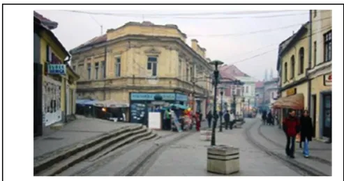
All zones in Tuzla city must be connected to each other and with the outer parts of the elements of civil engineering works with roads, railways, bridges, piping systems and other overhead and underground installations. Tuzla (Fig. 1) is the only city in Bosnia and Herzegovina, with salt exploitation. Also, Tuzla is the only city in Europe with artificial salt lakes and waterfalls. For reasons of daily subsidence, the issue of building roads and micro-tunnels is even more complex.
A. Road Design
The road is the land route, which is consciously directed action created or qualified to perform road traffic.
Vol. 2 Issue 3, March - 2016 The road is an engineering facility that is used for
transporting people and goods, or any public road or other surface on which traffic is carried out. First roads were inherited from animals. The man later was increasingly aware of their work invested in improving existing and building new roads. In this era of development of roads should be stated 'tea', 'silk' and 'salt' road. The level of development of road construction was in certain epochs in different parts of the world different. The oldest known roads in Babylon come from 3000 BC. The most important period of development of road construction is considered to be periods of construction of Roman roads [1]. The final impetus for the current rapid progress of road construction is given the invention of the car.
B. Hull Road
Movement of vehicles requires a certain area with certain diameter and longitudinal inclination to the axis of the road. The hull road or lower layer of road is artificial body built on natural terrain. According to the position of the ground surface in relation to the road surface, the body can be in the embankment, snick, notch, gallery, bridge, tunnel, etc. The main components of the superstructure with the pavement edge are strips, curbs, trails to stop the vehicle and shoulders [15].
Construction of road should assume the entire burden caused by vehicles. The choice of optimal design and its structure shall be based on the following elements: traffic, characteristics of the soil in the lower machine, local climatic and hydrological conditions and characteristics of the longitudinal profile of road. Empirical research has demonstrated that the life of a layer is dependent on: permanent base deformation, permanent deformation or loss of texture, fatigue cracking, low temperature cracking, adhesion failure, aggregate crushing or polishing [2].
C. Road Profile
Width of the road depends on the speed, type and number of vehicles on average, the character of the terrain, and the categories of travel and traffic density. On the roads of the first order on flat terrain maximum width is 7.0 m for two-way ride. The cross section of road may have a bilateral or unilateral inclination angle. Size of cross slope in road, depends on the type of pavement, the longitudinal gradient, the amount of water in sediment and climatic conditions (from 1.5 to 4%).
D. Road Construction
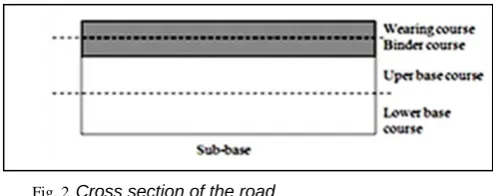
The main elements of the pavements are: the base, the lower base, upper base and wearing course (Fig. 2). The base is a 'foundation' of pavement. It is important to have a uniform capacity that is made of quality materials. Determination of the total thickness of pavement, thickness and arrangement of the individual layers and the criteria for the installation and control installation is called dimensioning pavement [1,13]. The upper surface is one or more layers that lie
just above of the curtain. Every material which has a CBR>80% can be used for the upper surface. The effect of vertical force is transmitted at an angle φ which depend on the type of material in the structure (φ=30-70°). The curtain on its surface receives all the external forces: the vertical, tangential longitudinal and transverse tangential.
The substrate is made from different types of materials: gravel, crushed gravel, crushed stone, concrete and other substrates consists of two or more layers of gravel, the total thickness of 15-20 cm (Tables 1-2).
Two layers of crushed stone have the total thickness of 15-20 cm. The base from crushed stone and gravel of the total thickness is 21-33 cm. The surface of cement concrete has a total thickness of 15-25 cm. In this case the layer has to make joints. The surface of the stabilized soil has a thickness of 15-30 cm. Tampon layer and layer serves to protect the purity of road from the harmful effects of frost and other adverse effects. The thickness of the layer purity is 10-20 cm and 20-50 cm buffer layer [1,6].
The curtain should be resistant and with less thick to be more economical. Layer of protection shall direct impacts of vehicle loads and environmental factors. Thickness of the wearing course is given in the Table 3 for the construction of modern pavements, and there are two basic types: flexible and rigid [1].
Fig. 2. Cross section of the road
TABLE I. CHARACTERISTICS OF SUBSTRATE IN THE ROAD CONSTRUCTION
Type of Substrate
CBR (California Bearing Ratio)
Minimum thickness of lower
substrate (cm)
Weak < 2% 15
Normal 2% < CBR < 15% 8
Very
strong CBR > 15% 0
TABLE II. VALUE OF CBR DEPENDING ON THICKNESS OF SUBSTRATE
CBR (California Bearing Ratio) on Layer (%)
The thickness of the lower substrate (cm)
< 2 28
2 - 4 18
4 – 6 13
6 – 15 8
TABLE III. THICKNESS OF DIFFERENT TYPES OF LAYER
Layer Thickness (cm)
crushed 6-15
gravel 20
small cubes 8-10
big cubes 16-18
cobble 20
cement concrete 6-7
asphalt macadam 7-8
asphalt concrete 2,5-8,0
mastic asphalt 4-5
asphalt mats 2,5-3,0
E. Dimensioning of Road Structure
Determination of the total thickness of pavement, thickness and arrangement of the individual layers and the criteria for the installation and control installation is called dimensioning pavement [1]. Determining the dimensions of pavement from an economic point of view is the most important issue because even for at least reducing the thickness of the structure can bring huge savings. Thickness of the pavement depend on: the size of the load by wheel, the size of the contact surface between wheel and road, the type and volume of traffic and physical characteristics of the ground troops of the road. There are several methods for the dimensioning and the most common are:
- Methods for classification of the soil depend on soil quality.
- Experimental methods are based on an examination of power to cope.
- Theoretical methods are based on the determination of internal stresses in the road.
F. The Load of Road
The main factors that influence on the behavior and durability of the pavement: traffic load, carrying capacity of the bed layer and the impact of the environment. The traffic loading is measured in ''equivalent light vehicles (elv's)'' per line, where heavy vehicles are converted to equivalent light vehicles using assumed ''equivalency factors'' (one heavy vehicle has 40 elv's). Traffic load on the pavement structure is considered by analyzing the following elements:
- the number and spacing of axles of vehicles, - the size of loads that are transmitted through individual wheel vehicles,
- the size and shape of the contact surface between the wheels of vehicles and road,
- load distribution on the contact surface, - the total number of individual axle loads,
- distribution of traffic load in the transverse profile of road,
- duration load in the individual layers of the pavement directly crossing the wheels of the vehicle.
All vehicles are moving at an imaginary axis in the profile of road. Knowledge of the zone in which the moving vehicle, allows determination of the most loaded zone of road, and therefore the potential of possible overload. During of movement the vehicle comes to the appearance of horizontal forces in the pavement. When sizing road construction should be hold in mind that the size of the load by wheel had impact on the stress condition, and number of load repetitions to fatigue [6].
The impact of the vehicle is transferred to the pavement structure over wheels. The wheels are supplied with tires. The size and shape of the contact surface between the wheel and road, and the size of the specific load on the surface is one of the most important facts. The size of tire pressure depends on the mass of the vehicle and moves the following limits: - passenger cars 0.20 MN/m2
- medium trucks 0.50 MN/m2 - heavy trucks 0.70 MN/m2.
The most common standard for loads is 100 kN per axle and 160 kN at a double axel.
G. Culverts
Culverts are structures for drainage where the water is leaking through the hull of the road, whether on water from natural streams or protective ditches. In most cases, they are designed and built as standard facilities. The size of the culvert is determined by hydraulic calculation [3]. According to materials it is divided into: concrete, reinforced concrete, pre-stressed concrete, stone and metal.
III. NUMERICAL MODELING
The finite element method (FEM) is perhaps the most widely applied numerical method in engineering today, because of its flexibility in handling material heterogeneity and anisotropy, complex boundary conditions and dynamic problems. The principal FEM disadvantage remains the poor ability to represent the stress-strain behavior of a system near the breaking point, because, being a continuum method, it does not admit the separation between adjacent elements [3,8,12,17].
Vol. 2 Issue 3, March - 2016 - The layer components and geometry are too
complex to use simple isotropic models.
- The ability of FEM to model complex stress analysis problems.
- Enabling the approximation of material characteristics by the collective behavior of all the elements (stresses and strains are able to be determined in each of the elements using the applicable elastic and visco-elastic methods).
- The availability of proven existing modeling software [2,3].
A. Description of the Model
In numerical modeling of construction of micro-tunnel continuous method can be used. This method require the division of the problem domain into elements of standard shapes and imply that at all points in the system the materials cannot be broken into pieces [16,18]. All points originally in the neighborhood of a certain area remain in the same zone throughout the deformation process. These sub-domains must satisfy the governing differential equations of the problem and the continuity conditions at their interfaces with adjacent elements [8].
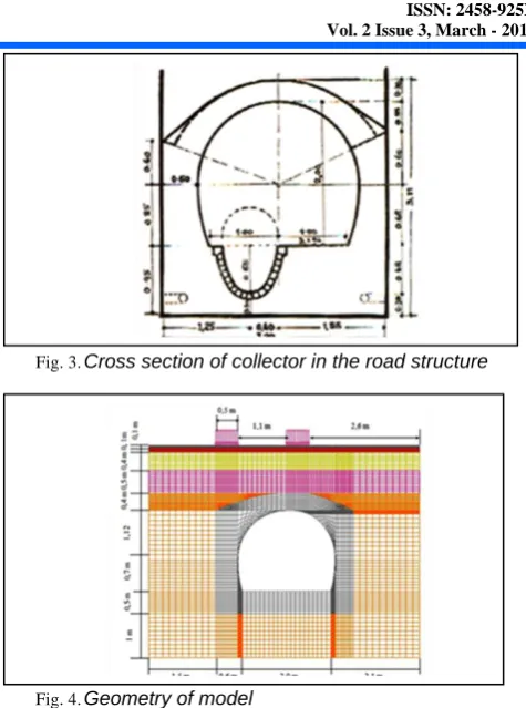
The aim of this paper is to determine the effectiveness of some pavement materials for reducing damaging of the road and micro-tunnel. The model had load only by its own weight in the first step. In a second step, the load is made by halves of contact patches that simulate the rear axle of a bus (80 kN). The contact patches were assumed to be circular area with diameter of 210 mm, approximated for modeling purpose to a square 200 mm wide. The difference in area between circle and square was kept in regard varying the pressure of the load on the surface. The rear axle of a heavy vehicle very often has dual wheels, so a total of four contact patches were modeled on the pavement [8]. Numerical analysis was carried out by means of the ADINA program system. An automatic generator was used to create the finite element mesh. The micro-tunnel tube (collector) has a cross-section area of 5 m2 (Fig. 3).
B. Generation of the mesh
The modeled area covers an area about 21 m width and 17 m in height (Fig. 4). An automatic generator was used to generate the finite element mesh. Four-nodded quadrilateral and triangular elements, which enabled a sufficiently accurate analysis to be performed, were used for the modeling [7]. In the analysis have been used 2-D elements for plane strain shown in YZ plane. Elements typically used in the ADINA program are izo-parameter finite elements. For the calculation of matrix elements and vectors used numerical integration Gauss points. For geometrically non-linear analysis, the position of the Gauss integration points are constantly changing as the element is subject to deformation and the reaction material and still gives you the integration points. Geometry of the model is presented on Fig. 4.
Fig. 3. Cross section of collector in the road structure
Fig. 4. Geometry of model
The model has 7440 nodes and 7225 elements. Finite element mesh created via surfaces adequate element groups. Each surfaces divided in 10 subdivisions by y and z axis. The model has 6 element groups with predefined types of materials. The first element group has 700 2D solid elements same as next three groups. The fifth element group has 2400 2D solid elements and last has 2025 2D solid elements.
C. Boundary conditions
The vertical edges (Fig. 5) of the whole area were fixed against horizontal displacement (mark B), and the bottom end was secured against vertical and horizontal displacement (mark C).
D. Material Properties
Formulation of material models is given through the geotechnical Mohr-Coulomb's model material, which is used to define small and large displacements. In both cases, the assumed stresses are small. When used in the formulation of large displacement, as in this case, the Total Lagrangian’s formulation is appropriate.
The input parameters of the subsoil were determined on the basis of the results of the engineering-geological investigations (Table 4). For the computational models, the input data from Table 4 were considered [7].
This model will be able to assist in the added determination of the fundamental binder properties on layer performance, and ability of the layers to contribute to the overall performance of the pavement [2]. Design methods for prediction of structural pavement elements, lifetimes, and assessment of requirements for design traffic loads, are increasingly based on design methods (methods based on principles of mechanics such as elasticity, plasticity, visco-elasticity), rather than empirical methods (based on experience or index properties – such as CBR, limiting deflections, etc.) [2].
TABLE IV. THICKNESS OF DIFFERENT TYPES OF LAYER
Soil Sub-base
Base-course
Binder-course
Wearing course
E
(MN/m2) 100 50 30 20 10
ν 0.3 0.3 0.4 0.4 0.4
γ
(MN/m3) 0.0022 0.002 0.0019 0.0018 0.0018
φ (°) 33 30 28 23 22
C
(MN/m2) 10 7 3 3 3
E. Failure criterion
The modeling of road surfacing layers using mechanistic principles with determined failure and fatigue criteria or relationships would enable assessment of the layers expected lifetime, inclusion of different component material characteristics and variations, varying traffic and environmental conditions. The feasibility of the development of a mechanistic performance behavioral model for design and assessment was examined using specific tools of finite element analysis [2]. In this calculation it was taken in consideration two-dimensional plain-strain problems with the Mohr-Coulomb constitutive model, used to describe the soil material properties [4,5].
F. Load
The determination of applied loads representing as real a reflection of possible actual traffic loading and contact stresses on layers was required. A detailed assessment and interpretation of current available data, focused on the geometry of the FEM model, was undertaken with the objective of defining a prototype model traffic load [2]. Stresses induced by the traffic are analyzed in the layer in terms of vehicle type (relative effect between heavy and light vehicles) and in terms of stress variation with load-time function. In this analysis is applied 'Mass proportional' load as well
as pressure for determining impact of vehicle on the road.
IV. COMPUTATION RESULTS AND ANALYSIS
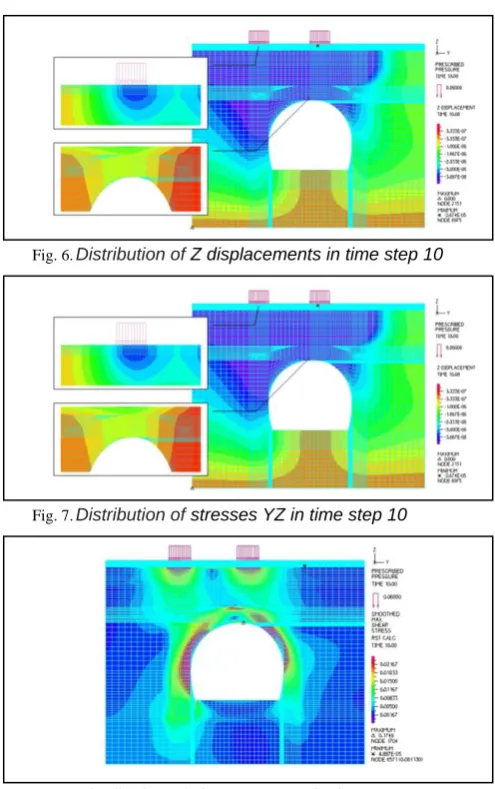
Next figures represent distribution of displacements, stresses and strains at the model. Z displacement in time step 10 (Fig. 6), when is applied 150 per cent of the maximum load on the road (provided the movement of heavy vehicles), has a maximum from -2.67E-05 meters. For all three cases of the load were obtained values of displacement ranging from -3.565E-06 to -2.67E-05 m and they will have a significant impact on a concrete lining or on the structure of road construction.
Stress YZ in time step 10 (Fig. 7) operates when the current 150 per cent of the maximum load on the road (provided the movement of heavy vehicles) has a maximum of 0.06175 MN/m2.
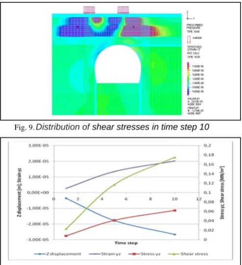
Changes in the distribution of stresses are notable below the wheels of vehicle and the lining culvert with increasing load value. Shear stress at time step 10 i presented in Fig. 8, when is 150 per cent of the maximum load on the road. The value of the minimum shear stress ranges from 6.526 E-06 to 4.887 E-05 MN/m2, while the maximum value ranges from 0.0223 to 0.1749 MN/m2.
Fig. 6. Distribution of Z displacements in time step 10
Fig. 7. Distribution of stresses YZ in time step 10
Vol. 2 Issue 3, March - 2016
Fig. 9. Distribution of shear stresses in time step 10
Fig. 10. Distribution of estimated maximal values trough time steps
YZ strainattimestep 10(Fig. 9)shows the value of the minimum value -1.75E-05 and maximum value 2.015E-05. The effect of heavy (80 kN axle) and light vehicle traffic (elv. of 25% tire inflation pressure of heavy vehicle) on the road is summarized in Fig. 10.
It is evident that with increasing time step ie., with increasing load on the road, growing all the output parameters of the estimation. Fig. 10 presents extreme values in time step 1, 5 and 10 for the entire model. It is clear that values of z displacement are insignificant, what indicates stability of road construction as well as concrete culvert. Stress yz shows a substantial increase of value from 0.00823 to 0.0617 MN/m2. The same changes appear both in road construction and culvert and for shear stress and strain yz. However, even the maximum value does not have such intensity that could lead to damage of pavement or culvert.
V. CONCLUSION
The main goal of the research was to verify the application of suitable numerical models on the basic type of underground structures. The analysis was carried out by means of modeling using the Finite Element Method implemented in ADINA software. An automatic generator was used for generating the finite element mesh. For the modeling we used quadratic and triangular elements, which enable a sufficiently accurate analysis to be performed. The design and monitored parameters at the cross profile of collector and road were used as source data for the analysis. Based on of all mentioned information, it can be concluded that the numerical modeling and computer simulations play an important role in the decision making process in designing of road construction and closed channel that is under that road. With presented
simulation it is possible, in a relatively short time, give optimal solution for construction that would satisfy both the safety and economic as well as time effect. This particularly applies to possible savings at time realization of optimal construction as well as economic saving in terms of finding the optimum thickness of road layer. As further research, it will be a good idea to find the optimal structure of closed channel in situation when road has to be specific design. It should be noted that accuracy of the output values significantly depend on accuracy of laboratory testing of input parameters for construction layers of the road.
REFERENCES
[1] Z. Korleat, Uvod u Projektiranje i Gradjenje Cesta [Introduction to Design and Build of Roads], University of Zagreb, Zagreb, Croatia, 1995
[2] T. Milne, K. Jenkins, “Towards modelling road surfacing seal performance: performance testing and mechanistic behavioural model,” Journal of the South African institution of civil engineering, vol. 3, 2005, pp. 2-13.
[3] T. Milne, M. Huurman, M.F.C. Van de Ven, K.J. Jenkins, A.Scarpas, C. Kasenberg, “Towards mechanistic behaviour of flexible road surfacing seals using a prototype FEM model,” Proceedings of the 8th Conference on Asphalt Pavements for Southern Africa
(CASPA’04), Sun City, South Africa, 2004,
[http://www.researchgate.net/publication/228693242_ Towards_mechanistic_behaviour_of_flexible_road_su rfacing_seals_using_a_prototype_FEM_model]
[4] T. Ninouh, M. Guenfoud, “Numerical simulation of idealized road structure,” Journal Engineering Applied Sciences, vol. 3, 2008, pp. 64-69. [5] N. Yukio, “Numerical simulation of tire traction on various road conditions,” Rubber Chemistry and Technology, vol. 80, issue 3, 2007, pp. 412-435.
[6] B. Huang, L.N. Mohammad, M. Rasoulian, “Three dimensional numerical simulation of asphalt pavement at Louisiana accelerated loading facility,” Transportation Research Board, vol. 1764, 2001
[7] J. Bartak, M. Hilar, J. Pruska, “Numerical modelling of overburden deformations,” Acta Polytechnica, vol. 42, issue 1, Czech Technical University Publishing House, Czech, 2002
[8] F. Grandi, V. Vignali, “Traffic vibration damping: The influence of pavement materials constitutive models,” 4th International SIIV Congress, Palermo, Italy, 2007
[9] B. Liu, T. Li, Y.Han, “Numerical modeling of a subway construction accident: case history and analysis,” http://www.paper.edu.cn, last access: 21.01.2016.
Nationalpark-Forschung in der Schweiz (Switzerland Research Park), vol. 101, issue 9, 2012, pp. 363-371.
[11] A. Nuric, S. Nuric, L. Kricak, R. Husagic, “Numerical methods in analysis of slope stability,” International Journal of Science and Engineering Investigations, vol. 2, issue 14, 2013, pp. 41-48.
[12] A. Nuric, S. Nuric, L. Kricak, I. Lapandic, R. Husagic, “Numerical modeling and computer simulation of ground movement above underground mine,” International Conference on Environmental Monitoring, Simulation and Remediation 2012, World Academy of Science, Engineering and Technology, Berlin, Germany, 2012, pp. 361-369.
[13] Ch. Zheng, H. Xu, H. Li, D. Dong Xiang, “Road pavement design in Northwestern China Grassland,” Journal of the Eastern Asia Society for Transportation Studies, vol. 6, 2005, pp. 118-193.
[14] A. Nawar, A. Al-Asady, S. Abdullah, A.K Ariffin, S.M. Beden, M.M. Rahman, “Comparison between experimental road data and finite element analysis data for the automotive lower suspension arm,” European Journal of Scientific Research, vol. 29, issue 4, 2009, pp. 557-571.
[15] P. Aggarwal, K.G. Sharma, K.K. Gupta, “Modeling of unreinforced and reinforced pavement composite material using hiss model,” IJE Transactions B: Applications, vol. 20, issue 1, 2007, pp. 13-22.
[16] M. Grujicic, H. Marv, G. Arakere, I. Haque, “A finite element analysis of pneumatic-tire/sand interactions during off-road vehicle travel,” Multidiscipline Modeling in Materials and Structures,
vol. 6, issue 2, 2010, pp. 284-308. doi:
10.1108/15736101011068037.
[17] Z. Ding-Bang, Z. Chuan-Bo, L., Yang-Bo, Y. Jian-Yi, “Physical model test and numerical simulation study of deformation mechanism of wall rock on open pit to underground mining,” IJE Transactions B: Applications, vol. 27, issue 11,2014,pp.1795-1802.