Odey et al. World Journal of Engineering Research and Technology
DEVELOPMENT AND PERFORMANCE EVALUATION OF WOOD
COMPONENTS IN STANDING FAN
S. O. Odey*1 and O. O. Okon2
1,2
Department of Wood Products Engineering, Cross River University of Technology,
Calabar, Nigeria.
Article Received on 20/12/2018 Article Revised on 10/01/2019 Article Accepted on 31/01/2019
ABSTRACT
Gmalina arborea, Zebrawood and Plywood were utilized in the design,
fabrication, replacement of component parts and testing of fan.
Plywood, Gmalina arborea and Zebrawood were used for the
construction of the blades, fan’s root plate cover, stand and base
respectively. The four blade sizes of diameters, 240 mm, 242.5 mm,
247.5 mm, and 282.5 mm were each coupled to the fan Hub and then
mounted on the rotating shaft and tested. The various fabricated parts of the fan were
coupled. The fan was tested for velocity, airflow and efficiency. Digital Anemometer was
used in taking readings. Correlation and regression analysis were carried out on the data.
Results showed that blades with the diameters of 240 mm, 242.5 mm, 247.5 mm, and 282.5
mm produced an average airflow of 3.65 cms, 3.24 cms, 3.94 cms and 4.41 cms respectively.
Comparing the wooden fan blade of 282.5 mm diameter with conventional plastic/metal fan
blade of same size showed that the velocities were 4.30 m/s and 4.64 m/s respectively, with
airflow of 4.41 cms and 4.77 cms respectively, with efficiencies of 89% and 90%
respectively. Fan velocity and airflow had positive correlation with blade area and negative
correlation with density of blade. Velocity and airflow of 0.748 and 0.815 respectively
resulted when the density was 0.560. While velocity and airflow of -0.710 and -0.750
respectively were realized when the density was -0.372. Regression equation with coefficient
of linearity, R2 of 0.999 was obtained, showing effectiveness of wood as engineering material
in fans production.
World Journal of Engineering Research and Technology
WJERT
www.wjert.org
SJIF Impact Factor: 5.218*Corresponding Author S. O. Odey
Department of Wood
Products Engineering, Cross
River University of
Technology, Calabar,
KEYWORDS: Development, Performance, Evaluation, Wood, Standing Fan, Velocity, Airflow.
1.0 INTRODUCTION
Fans are widely used for circulating air for the purpose of cooling in rooms, buildings,
mechanical, electrical and electronic gadgets to create a more comfortable atmosphere. Most
postharvest crops processing and storage equipment utilize fans for their effective operations.
Agricultural Engineering machines such as threshers, Sheller, separators, winnowers and
grains destoners incorporate different types of fans for effective operation. There are various
types of fans used for various purposes ranging from larger to smaller sizes. They include:
Standing fans for domestic and industrial and office uses, ceiling fans can also be used at the
office and in homes to provide cooling system. We also have table fans, wall fans, propellers
used at aircraft, fans used at kiln for wood seasoning, computer fan are mounted inside
electrical and electronic gadgets such as computers, motors and engines, air conditioners to
reduce high temperature during operation (Nobumasa, 1992, Naoki, 2006 and Yoshihiko,
2007).
Wood is the oldest and most widely used engineering materials. It is the only significant
building material that is grown, we have a natural inclination that building in wood is good
for the environment (Ramage et al., 2017). It is renewable and readily available throughout
the world and in Nigeria, wood is available in almost all the geopolitical zones. It has high
ratio of durability and performance when properly treated and it is cheaper than other
materials like metals, plastics, composite materials and alloys used for the design of fans and
other devices (USDA, 2010). The tropical region of the world is endowed with different types
of wood species relevant for utilization in fans development, but this is scarce. Hence, there is
great necessity in the use and application of wood in the design of fans. Hardwoods and
softwoods are useful for this purpose (Richardson, 1998).
Fan is a mechanical device that causes a movement of air and is used to induce airflow for a
cooling purpose (Bill, 2005). Fans creates flow within a fluid, typically in liquids such as
water and in gases such as air. A fan consists of a rotating arrangement of vanes or blades
which act on the air fluid. The rotating assembly of blades and hub is known as an impeller, a
rotor, or a runner. Most fan blades are protected by the mesh which serves as protection
against curious finger and preventing damage to the blades and injury to man (Wedel et al.,
According to Hansan (2014), most fans are electrically powered. But there are other sources
of power including hydraulic motor and internal combustion engines. Generally, fan blades
will always rotate when placed in the direction of flow of a fluid, however, such does not
produce enough airflow relevant to provide cooling system. Fans are generally made from
metallic and plastic materials but there are many more materials that can be used in the
design of fan especially the blades. Reports show that the cost of metals and plastics
generally are becoming higher than wood as construction materials (Yahya, 2010).
1.1 Types of Fan
The three main types of fans used for moving air are axial fan, centrifugal (radial) fans and
cross flow (tangential) fans (Ferguson, 1942).
The Axial Fans are made up of blades that forces air to move parallel to the shaft about which the blades rotate. Axial fans blow air across the axis of the fan, linearly. This is the
most commonly used type of fan and is used in a wide variety of applications (Randon, 2008,
AMCA, 2011, Bass, 1996).
The Centrifugal Fan has a moving component (impeller) that consist of a central shaft about which a set of blades form a spiral pattern. Centrifugal fans blow air at right angles to the
intake of the fan, and spin (centrifugally) outward to the outlet. An impeller rotates, causing
air to enter the fan near the shaft and move perpendicular from the shaft to the opening in the
scroll shape-casing. A centrifugal fan produces more pressure for a given air volume but are
typically noisier than comparable axial fans (Yahya, 2010, AMCA, 2011).
The Cross Flow Fan is a squirrel cage rotor (a rotor with a hollow center and axial fan blades along the periphery). Tangential fans take in air along the periphery of the rotor and
expel it through the outlet in a similar fashion to the centrifugal fans cross flow fans give off
an even air flow along the entire width of the fan and are very quiet in operation. They are
comparatively bulky, and the air pressure is low. Cross flow fans are often used in air
conditioners and automobile ventilation systems (Randon, 2008).
1.2 Research Objectives
The main objectives of this research are design, fabricate, replace wooden components of
2.0 MATERIALS AND METHOD 2.1 Experimental Site
The work was carried out in the Department of Wood Products Engineering, Faculty of
Engineering, Cross River University of Technology, Calabar, located on coordinates,
4°57′0″N 8°19′30″E.
2.2 Materials Required
i. Gmalina arborea was used to construct the fan’s root plate cover
ii. Plywood for the construction of the blade.
iii. Zebrawood for the construction of the stand and base.
iv. Sander sealant vanish and spar vanish for wood finishing
v. Sand paper 320 and 250 grit. For improving the smoothness of the wood.
vi. Record book for taking record of all measurement and readings.
2.3 Design Considerations
According to Hudson (2007) and complimented by Yu-Tai Lee et al. (2011), one of the most
important requirements of a fan wheel is that it must impart to the air stream a uniform
velocity and pressure over its entire area (Grainger, 2005).
a. The individual blade will be narrow at the tip. Where the blade velocity is light and will
widen toward the hub where more blade area is required due to lower blade velocity.
b. The angle of the blades to the plane of rotation will be minimum at the tip and increase as
the hub is approached.
c. Blade Discharge velocities
d. Hub size should be optimally large enough to pick up where the blades are no longer able
to carry load.
e. Pitch and Blade Angle
f. Number of Blades and the area of the total blade surface
g. Blade size in terms of width and length is important as this affects the efficiency.
h. Blade Speed - Proper wheel design must be closely correlated with blade speed since the
total pressure furnished by any wheel is proportional to the square of the RPM.
2.4 Design of Component Parts of Fan
The components of the fan including the blades, stand and base were designed based on the
overall system energy efficiency for an existing system can be expressed in terms of the
specific fan power (SFP). SFP is defined as the installed motor power of all the fans in the air
distribution system divided by the design airflow rate. SFP is expressed in terms of KW per
1000 CFM or in KW per ( /S) (McKenzie, 1997, Elizabeth, 2010, Lewis, 1996). The
components parts which were designed are shown in Tables 1 and 2 below.
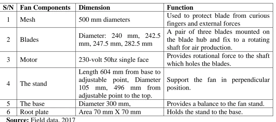
Table 1: Design Specifications of the wooden standing fan.
S/N Fan Components Dimension Function
1 Mesh 500 mm diameters Used to protect blade from curious
fingers and external forces
2 Blades Diameter: 240 mm, 242.5
mm, 247.5 mm, 282.5 mm
A pair of three blades mounted on the blade hub and fix to a rotating shaft for air production.
3 Motor 230-volt 50hz single face Provides rotational force to the shaft
which holes the blades.
4 The stand
Length 604 mm from base to adjustable point, Diameter 105 mm, 496 mm from adjustable point to the top.
Support the fan in perpendicular position.
5 The base Diameter 300 mm, Provides a balance to the fan stand.
6 Root plate Area 70 mm X 70 mm Holds the stand to the base.
Source: Field data, 2017
Table 2: Designed fan blades and their properties. Blade diameter (mm) Thickness (mm) Weight (g) Area (mm)2 Volume mm3 Density g/mm3
240 3 22.221 45238.9 135734.4 0.000164
242.5 3 22.743 46186.3 138576.9 0.0001641
247.5 3 22.771 48110.6 144350.4 0.01577
282.5 2 21.571 62679.7 125375.6 0.01721
Source: Field data, 2017
2.5 Tools and Machines Used in the Construction a. Flexible curve for measuring blade circumference.
b. Pencil and meter rule used for measuring fan components
c. Hand drilling machine for drilling the bold holes on the root plate metals
d. Lathe machine used to create round surface on the wood.
e. Drilling machine with 3 inches bit size. For drilling the stand of the fan.
f. Narrow band saw used to cut the shape of blades.
g. Welding machine for welding the root plate metals.
i. Digital Anemometer for measuring velocity and airflow.
j. Hand saw for cutting various components of the fan.
k. Grinding stone machine for cutting the metal sheet.
2.6 Fabrication of the Designed Wood Components of Fan
i. Meter rule was used to measure the length of the base of the fan and the stand of the fan
from the wood and the points were marked with a pencil.
ii. Hand saw was used to cut out the wood into various components of the fan
iii. Lathe machine was the most important machine I used to turn the wood into the desired
circular shape.
iv. I used grinding stone to cut the metal I used as the base root metal.
v. Hand drilling machine of 10mm bit was used to drill the bolds holes of the root metal.
vi. Sand paper (320 grits and 250 grits) was used to sand the wood give it a smooth finish.
vii. Cutting of the blade was done by means of the narrow band saw into different blade
sizes.
viii.Final finishing was done by first praying the fan with a sander finish. Allow it for some
30 minutes to dry. Then I used 320grt sand paper to the surface clean it with a moist
cloth and allowed to dry. I now used a neutral spar vanish with thinner to spray again
twice to obtain the final brilliant and smooth finish.
ix. Coupling of the components was done by screw driver and 8mm diameter spanner to
fasted the various components.
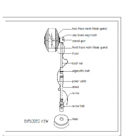
2.7 Basic Description of the Fan
The developed fan is made up of the following basic parts: Base - this supports the entire mechanism. Adjustable Stand – which carries other parts. Motor Housing - this consist of the squirrel cage induction motor to which blade assembly is attached. It is operated by a
single phase electric supply, 230 V (50 Hz, 55W). This is operated by 3-speed control switch,
usually where you will find the on-off (regulator) with speeds-low, medium and high. There
is also Blade/Impeller Assembly - which cuts the air and pushes it forward. While the Blade
Guard - prevents curious fingers from suffering injury. Oscillator makes it possible for the fan to rotate left and right.
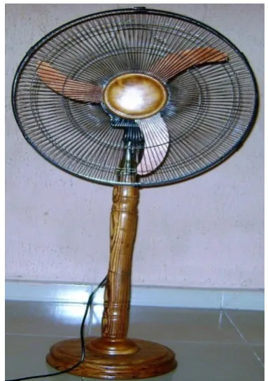
Figures 1 and 2 show the isometric drawings of the designed fan. While Figures 3 to 6 show
the pictorial views of the fan using different types of blade designs. Whereas Figure 7 and 8
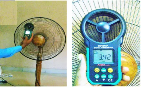
2.8 Coupling and Testing of Fan
The various fabricated components of the fan including the blades, stand, base and other
essential parts were coupled. The fan was connected to a power source and tested for
velocity, airflow and efficiency. The various blade sizes were tested. In testing fan
performance, a portable MASTECH Digital Anemometer, model MS6252A was used in
taking readings.
Figure 1: Front view of fan.
Figure 3: Fan with Blade Diameter, 282.5 mm.
Figure 4: Fan with Blade Diameter, 282.5 mm.
Figure 7: Positioning the Anemometer. Figure 8: Taking reading with Anemometer. 3.0 RESULTS AND DISCUSSION
3.1 Wooden fan Performance Analysis
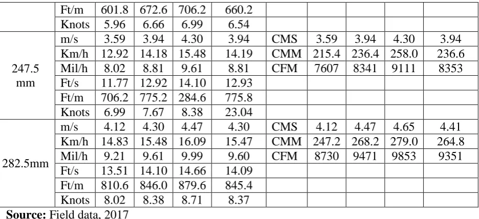
Data obtained from testing the fan with digital Anemometer are displayed on Table 3 below.
Shown below are blade sizes of various diameters 240mm, 242.5mm, 247.5mm, and
282.5mm. Their performance was based on the following units: Velocity in m/s, km/h, mil/h,
ft/s, ft/m and knots while air flow is in cubic meter per second (CMS), cubic meter per minuts
(CMM) and cubic feet per minute (CFM).
Table 3: Fan blades, velocity and airflow data of fan during operation. Blade
diameter (mm)
Velocity Average
Velocity
Air Flow Average
Air Flow
Units 1 2 3 Units 1 2 3
240 mm
m/s 3.42 3.59 3.94 3.65 CMS 3.42 3.59 3.94 3.65
Km/h 12.31 12.92 14.81 13.14 CMM 205.2 215.4 236.4 219
Mil/h 7.84 8.02 8.81 8.16 CFM 7247 7607 8348 7734
Ft/s 11.21 11.77 12.92 11.97
Ft/m 672.6 706.2 775.2 718
Knots 6.66 6.99 7.67 7.11
242.5 mm
m/s 3.06 3.42 3.59 3.42 CMS 3.24 3.42 3.59 3.42
Km/h 11.02 12.31 12.92 12.08 CMM 194.4 205.0 215.4 614.8
Mil/h 6.84 7.64 8.02 7.5 CFM 6865 7247 7607 7240
Ft/m 601.8 672.6 706.2 660.2
Knots 5.96 6.66 6.99 6.54
247.5 mm
m/s 3.59 3.94 4.30 3.94 CMS 3.59 3.94 4.30 3.94
Km/h 12.92 14.18 15.48 14.19 CMM 215.4 236.4 258.0 236.6
Mil/h 8.02 8.81 9.61 8.81 CFM 7607 8341 9111 8353
Ft/s 11.77 12.92 14.10 12.93
Ft/m 706.2 775.2 284.6 775.8
Knots 6.99 7.67 8.38 23.04
282.5mm
m/s 4.12 4.30 4.47 4.30 CMS 4.12 4.47 4.65 4.41
Km/h 14.83 15.48 16.09 15.47 CMM 247.2 268.2 279.0 264.8
Mil/h 9.21 9.61 9.99 9.60 CFM 8730 9471 9853 9351
Ft/s 13.51 14.10 14.66 14.09
Ft/m 810.6 846.0 879.6 845.4
Knots 8.02 8.38 8.71 8.37
Source: Field data, 2017
Table 4 shows the different sizes of blades with different parameters. It can be seen from the
data on Table 4 that velocity and air flow is greatly influenced by the blade surface area. The
same operating power yielded different velocities and airflows for different blade sizes.
Table 4: Constructed wooden fan blades parameters and their efficiencies. Blade diameter (mm) Thickness (mm) Weight (g) Area (mm)2 Volume mm3 Density g/mm3 (1x10⁻³) Air Velocity (m/s) Air Flow (cms) Efficiency (%)
240 3 22.221 45238.9 135734.4 0.164 3.65 3.68 86
242.5 3 22.743 46186.3 138576.9 0.1641 3.42 3.59 90
247.5 3 22.771 48110.6 144350.4 15.77 3.39 3.94 83
282.5 3 21.571 62679.7 125375.6 17.21 4.30 4.41 89
As shown in Table 4 above the blade with the diameter of 240 mm produced velocity of 3.42
m/s at the minimum speed, when the fan speed was increased to the medium speed, the
velocity increased to 3.59 m/s and 5.94 m/s at the maximum speed, giving an average of 3.65
cms. The same was observed in the resultant airflow being 3.42 cms at the lowest speed, 3.59
cms at the medium speed and 3.94 cms at the maximum speed, yielding an average of 3.65
cms.
On the other hand, blade size of diameter, 242.5 mm produced lesser velocity of 3.06 m/s at
the minimum speed, 3.42 m/s at medium speed and 3.59 m/s at maximum speed, giving an
average velocity of 3.36m/s and airflow of 3.24 cms at the minimum speed, 3.42 cms at
medium speed and 3.59 cms at maximum speed giving an average airflow of 3.42 cms. This
important factor to consider when selecting blades that will produce a better velocity and
airflow.
It can also be observed that there was increase in velocity and airflow when the blade
diameter was increased to 247.5 mm. Velocity of 3.59 m/s at minimum speed, 3.94 m/s at
medium speed, 4.30 m/s at maximum speed with an average velocity of 3.94 m/s were
recorded. The resultant airflow was 3.59 cms, 3.94 cms, 4.30 cms with an average airflow of
3.94 cms at the respective fan velocities.
Finally, increasing the blade to diameter of 282.5 mm, the fan produced velocities of 4.12
m/s, 4.30 m/s and 4.47 m/s and average velocity of 4.30 m/s. The resultant air flow was 4.12
cms, 4.47 cms and 4.65 cms with average air flow of 4.41cms. These results prove that
velocity and air flow are closely interrelated and determined greatly by the blade’s surface
area and speed of the blade.
Thus, comparing the wooden fan blade of 282.5 mm diameter with conventional plastic fan
blade of same size showed that the velocity as recorded by the anemometer were 4.30 m/s
and 4.64 m/s respectively. While the airflow in cubic meter per second (cms) for wooden
blade and plastic blade of same size were 4.41 cms and 4.77 cms respectively, with
efficiencies of 89% and 90% respectively. These results revealed that the wooden blade of
same diameter works efficiently well compared to the plastic conventional blade of same
size.
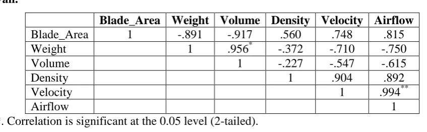
3.2 Relationship Between the Blade Sizes, Velocity and Airflow
The relationship between the blade area, weight, volume, density, velocity and resultant
airflow can be determined using the method of correlation and regression. Table 5 shows
results of correlation of blade properties and parameters during operation of fan. Results
showed that fan velocity and airflow had positive correlation with blade area and negative
correlation with density of blade. Thus a velocity and airflow of 0.748 and 0.815 respectively
resulted when the density was 0.560. While velocity and airflow of -0.710 and -0.750
Table 5: Results of Correlation of Blade Properties and Parameters during Operation of Fan.
Blade_Area Weight Volume Density Velocity Airflow
Blade_Area 1 -.891 -.917 .560 .748 .815
Weight 1 .956* -.372 -.710 -.750
Volume 1 -.227 -.547 -.615
Density 1 .904 .892
Velocity 1 .994**
Airflow 1
*. Correlation is significant at the 0.05 level (2-tailed).
**. Correlation is significant at the 0.01 level (2-tailed).
Regression equation was obtained for Air flow Af as the dependent variable while blade area,
Ab and blade velocity, V were the independent variables.
Airflow = - 0.49 + 0.003 Ab + 0.925 V
Af = - 0.49 + 0.003 Ab + 0.925 V
R2 = 0.999
Where,
Af = Airflow from fan
Ab =Blade Area
V = Fan Velocity
4.0 CONCLUSION
The research provided insight into the effective utilization of wood as an alternative material
in the production of fan compared to the conventional materials such as metals and plastics.
Wood species of different types exist in tropical rain forest region of Africa that have basic
engineering properties useful for the construction of different machines components. Wood is
naturally available and reclaimable through afforestation and proper conservation. Hence
there is a growing need for efficient utilization of this raw material in the design of
engineering products such as the electric fans. Gmalina arborea, Zebrawood and Plywood
were utilized in the design, fabrication, replacement of component parts and testing of fan.
Results obtained revealed that the wooden blades of same diameter works efficiently well
compared to the conventional plastic/metal blades of same size and has high economic value
with reduced cost of production, hence recommended for production and application in
fan blade. The test conducted on the fan showed that it has the potential to resist bending
stress and pressure as a result of centrifugal force induced on the blade as it rotates.
It is hereby recommended to make maximum utilization of these locally available
engineering materials in the design of engineering products for advancement in economy of
the nation and the world at large. Studies in the utilization of different species of hard and
soft woods in constructing engineering products such as fans and other machines should be
encouraged.
REFERENCES
1. AMCA (2011), Fans and Systems. Publication of Air Movement and Control Association
International, Inc. Assessed: October 28, 2017.
2. Bass, R. M. (1996), Factors influencing the aerodynamic design of low pressure axial fan
in industrial fan design. Lecture notebook Cranefield University.
3. Bleier, F. P. (1998), Fan Handbook selection, application, and design. McGraw Hill
companies.Inc. New York.
4. Elizabeth, T. (2010), The parts of a fan (internet). Available from
https//www.hunker.com/1242561.
5. Ferguson, C. G. (1942), Fans-their types, characteristics, and application.
6. Grainer, W. W. (2005). Ventilation Fundamentals. MMCT - 4145 8S1686 07/05 Dayton
Electric Manufacturing Co. © 2005. W.W.Grainger, Inc.
7. Hansan, K. F. (2014), Term paper on electric fan. Available from:
hp//www.scribd.com/doc/10027426.
8. Hudson (2007), The Basics of Air-Cooled Heat Exchangers. Hudson Products
Corporation, a subsidiary of Hudson Products Holdings, Inc. www.hudsonproducts.com.
Assessed: June 19, 2017.
9. Karl Kolmetz and Mela Widiawati (2015), Kolmetz Handbook Of Process Equipment
Design: Fin Fan Air Cooler Selection and Sizing, Engineering Design Guideline. KLM
Technology Group #03-12 Block Aronia, Jalan Sri Perkasa 2 Taman Tampoi Utama
81200 Johor Bahru, Malaysia.
10.Lewis, R. I. (1996), An important and practical advantage of free design.
Butterworth-Heineman press.
11.McKenzie, A. B. (1997), Axial flow fans and compressor aerodynamic design and
12.Naoki K. and Nikkan K (2006), Complete introduction to thermal design for electronics.
13.Nobumasa, k. (1992), Thermal design handbook, Asakura publishing.
14.Ramage, M. H., Burridge, H., Busse-Wicher, M., and Fereday, G. (2017), The wood from
the trees: The use of timber in construction. Renewable and Sustainable Energy Reviews,
Elsevier, 68(1): 333-359.
15.Randon, K.W. (2008), Course note for axial compressor design and performance of fan.
Lecture notebook, Cranefield university.
16.Richardson, S.E. (1998), Design and manufacture of wood blade for Windtunels fans.
NASA Center for AeroSpace Information 800 Elkridge Landing Road Linthicum
Heights, MD 21090-2934. National Technical Information Service, 5285 Port Royal
Road Springfield, VA 22161.
17.Smith, T. W. (1989), A practical approach to the design of axial and mixed flow fan.
American association for public opinion: Journal.
18.USDA (2010), Wood handbook—Wood as an engineering material. General Technical
Report FPL-GTR-190. Madison, WI: U.S. Department of Agriculture, Forest Service,
Forest Products Laboratory. 508 p.
19.Wedel T, Leung W, Banergjee R, et al. (2014), Break down of an oscillating table fan.
[cited 2014 Mar 10]; Available from: wentylacja.com.pl/ Attachment/Fan1-doc-1374 .
20.Cory, W. T. W (2005), Fans and ventilation: a practical guide. Published: Amsterdam ;
Elsevier, 2005.
21.Yahya, S. M. (2010), "14". Turbines Compressors And Fans (4th Edition) (4th ed.).
McGraw-Hill Education (India) Pvt Limited. pp. 622–628. ISBN978-0-07-070702-3.
Retrieved 13 May 2013.
22.Yoshihiko, A. (2007), Thermal design /countermeasure technologies symposium
―Selecting and using fans‖, Japan Management Association.
23.Yu-Tai Lee, Vineet Ahuja, Ashvin Hosangadi, Michael E. Slipper, Lawrence P.
Mulvihill, Roger Birkbeck, and Roderick M. Coleman (2011), Impeller Design of a
Centrifugal Fan with Blade Optimization. International Journal of Rotating Machinery,