Application Of Power System Stabilizer At Serir
Power Plant
T. Hussein, **A. Shamekh *
Electrical and Electronics Dept University of Benghazi
Benghazi- Libya
*Salh ABDALLA, **Salah Bohliqa General Electricity Company of Libya
Benghazi, Libya *[email protected]
Abstract—Power system instability as a result of
Serir power plant of one of the largest power plants of the general electricity company of Libya (GECOL) prevented the plant to be fully utilized specially at base load. Power system stabilizers (PSSs) were installed on the generating units of the power station at 2008, to improve its small and large signals stability, and enhance the stable generation limit. Particle Swarm Optimization (PSO) is used to determine the parameters of (PSS2A) off-line. A bench mark simulation problem of a single machine infinite bus power system equipment with gas turbine model is exploited to demonstrate the performance of the static excitation (ST1A) and PSS2A. The simulation results clearly indicate the effectiveness and validity of the studied PSS2A with updated parameters.
Keywords—power system stabilizer, static excitation system, swarm optimization technique.
I. INTRODUCTION
The power system is a complex nonlinear due to wide range of operating conditions, unpredictable fault locations and the loading conditions changing from time to time.
The power system stability can be defines as that property of a power system that enables it to remain in a state of operating equilibrium under normal operating conditions and to regain an acceptable state of equilibrium after being subjected to a disturbance. Rotor angle stability is the ability of the interconnected generators of the power system to remain in synchronism. The stability problem involves the study of the electromechanical oscillations inherent in power systems.
The common factor in this problem in the manner in which the electrical power of generators vary as their rotor oscillate [1].
To solve this problem supplementary control signal adds to the automatic voltage regulator called Power
System Stabilizer (PSS) which adding phase lead to compensate for phase lag which coming from automatic voltage regulator (AVR) time constant. The basic function of the PSS is to add damping to the generator rotor oscillations by controlling its field current and voltage using excitation system by auxiliary stabilizing signal. To add damping, the PSS must produce a component of electrical torque in phase with speed variations.
When system runs under AVR mode, the generator is the control plant. The PSS function is disabled and the output is zero. When PSS is enabled, the control plant becomes AVR and PSS controls which closed control loops in excitation system [2].
for various disturbance conditions for damping of oscillations while satisfying the design requirements. Deals with a design technique for the stability enhancement of a multi-machine power system using PSS in each machine which their parameters are tuned using particle swarm optimization technique PSO (PSO-PSS) introduced in [5]. Simulation results show that the (PSO-PSS) method guarantees robust performance under a multi of operating points.
This paper introduces simulation problem of a single machine infinite bus power system to demonstrate the performance of the static excitation (ST1A) and re-tuned power system stabilizer PSS2A.
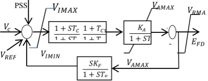
II. STA1 FAST STATIC EXCITATION SYSTEM
The static excitation equipment converts a 3-phase alternating current into a direct current which is used to generate the magnetic field in the synchronous machine. The excitation current can influence the machine voltage, the reactive power and the cos φ. Furthermore, the active power and/or the rotor displacement angle can be dynamically influenced (not stationary).
All components in these system are static or stationary, static rectifiers, controlled or uncontrolled, supply the excitation current directly to the field of the main synchronous generator through slip rings [1].
Type ST excitation systems in Fig. (1), in which excitation power is supplied through transformers or auxiliary generator windings and rectifiers.
In this type of system, the inherent exciter time constants are very small, and exciter stabilization not required.
.
The PI controller has to be converted to lead-lag filter. The parameters are listed in Appendix A.
Fig. 1, Type ST1A Excitation Model System
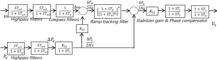
III. POWER SYSTERM STABILIZER (PSS2A)
Nowadays, Integral-of-Accelerating Power Stabilizer is widely used in power system stable control. The typical PSS is IEEE standard PSS2A(B) model as shown in Fig. (2).The input signals are the angular frequency of the rotor (ω) and the electrical power (𝑃𝑒), the two wash-out filters (𝑇𝑊1, 𝑇𝑊2) eliminate the steady state components of the inputs signals [6]. (𝑇6& 𝑇7)
represented the input filters. 𝐾𝑆2 is used to adapt the scaling of the two inputs and should be equal to (𝑇7⁄2𝐻), where H is the inertia constant of the generator and turbine. The ramp tracking filter (𝑇8, 𝑇9 ,M and N) is a low pass filter that eliminate any high frequency components. 𝐾𝑆1 determine the gain of the stabilizer and the lead-lag stages with non-windup limiter (𝑇1, 𝑇2, 𝑇3, 𝑇4) provide phase compensation [7]. Fig. of PSS2A is shown in Appendix (A). The setting of PSS2A are listed in Appendix B
IV. OVERVIEW OF PARTICLE SWARM OPTIMIZATION (PSO)
The PSO concept [8] is to change the velocity of each particle toward its global (𝑔𝑏𝑒𝑠𝑡) and local (𝑝𝑏𝑒𝑠𝑡) locations at each iteration [6]. The modified velocity of each agent can be calculated using the current velocity and the distance from pbest and gbest as shown below :
)
(
)
(
21
1 k
i k
i k
i i k
i
w
v
c
r
pbest
s
c
r
gbest
s
v
(1)where,
v
ik : velocity of particle i at instant 𝑘,
v
ik1 : velocity of particle at instant (𝑘 + 1),rand() : random number between 0 and 1,
s
ik : position of particle i at instantk
,
pbest : pbest of particle
i,
gbest : gbest of group,
w
i : inertia weight factor,
c
i : acceleration constantThe current position (searching point in the solution space) can be modified by the following equation.
1
1
ki k i k
i
s
v
s
(2)The PSO algorithm
The proposed algorithm to search for the optimal value of the power system stabilizer (PSS1A) parameters using PSO can be summarized as follows: 1. Initialize the swarm with initial positions and
velocities.
𝐸𝐹𝐷
-+
𝑉𝐼𝑀𝐼𝑁
𝑉𝑅𝑀𝐴𝑋
𝑉𝐴𝑀𝐴𝑋
𝑉𝐴𝑀𝐴𝑋
𝑉𝐼𝑀𝐴𝑋
𝑉𝑅𝐸𝐹
PSS
𝑉𝑐 1 + 𝑆𝑇𝐶 1 + 𝑆𝑇𝐵
1 + 𝑇𝐶1 1 + 𝑇𝐵1
𝐾𝐴 1 + 𝑆𝑇𝐴
2. Calculate the fitness function of each particle by Integral of the Square of the Error (ISE):
ISE
dt
t
e
0 2
. (3)
Where, 𝑒 = 𝜔 − 𝜔𝑑
: actual speed
d: desired speed3. Determine
pbest and
gbest positions.
4. Update the particle velocity using Eq. (1). 5. Update the particle position using Eq. (2).6. If the evaluation value of each particle is better than the previous
pbest, the value is set to
pbest. If the
bestpbest is better than
gbest, the value is set to
gbest.
7. If the iterations are exhausted, then go to step 8. Otherwise, go to step 2.
8. Plot
pbest,
gbest.
we select the best one which have small error Eq. (3), sometimes we used the controller's gains which got by the PSO as reference values and decreasing the error by changing these gains by trial and error.
The objectives of the designer is to obtain the minimum value of ISE by proper search of PSS2A parameters by PSO.
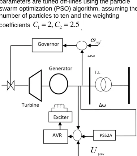
V. POWER SYSTEM DESCRIPTION
A three-phase generator rated 282 MVA, 20 kV, 3000 rpm is connected to a 230 kV, 10,000 MVA network through a Delta-star 210 MVA transformer.
At t = 1 s, a three-phase to ground fault occurs on the 230 kV bus. The fault is cleared after 3 cycles (t = 1.08 s).
During this system, we will initialize the system in order to start in steady-state with the generator supplying active power and observe the dynamic response of the machine speed deviation and of its active power.
Fig. 2, single machine infinite bus power system
VI. SIMULATION STUDY
The power system stabilizer (PSS2A) Serir Power Plant (SPP) is implemented as shown in Fig. 4. Its
parameters are tuned off-lines using the particle swarm optimization (PSO) algorithm, assuming the number of particles to ten and the weighting
.
5
.
2
,
2
21
C
C
s coefficient
Fig. 3, Power system model used in study
The performance of the PSS2A in SPP is evaluated by applying a large disturbance in the form of a three-phase fault of the transmission line. The fault occurs at 1 sec. and cleared at 0.08 sec.
Three different operating points (cases) are shown here to measure the performance of the power system stabilizer (PSS2A) in SEMIPOL .
Case (1)
Active Power 𝑃𝑒=0.9 pu Reactive Power 𝑄𝑒=0.114 pu
Case (2)
Active Power 𝑃𝑒=0.6 pu Reactive Power 𝑄𝑒=0.048 pu
Case (3)
Active Power 𝑃𝑒=0.37 pu Reactive Power 𝑄𝑒=0.0175 pu
Fig.4 :speed deviation case (1)
0 2 4 6 8 10 12 14 16 18 20 -5
-4 -3 -2 -1 0 1 2 3 4 5x 10
-3
t (sec)
S
p
e
e
d
d
e
v
ia
ti
o
n
p
u
with PSS without PSS
Active Power= 0.9 pu Reactive Power= 0.114 pu
Turbine
∆ω
Governor
AVR Generator
T.L
Δω x
Exciter
Fig.5 :Active Power case (1)
Fig.6 :Terminal Voltage case (1)
Fig.7 :speed deviation case (2)
Fig.8 :Active Power case (2)
Fig.9 :Terminal Voltage case (2)
Fig.10 :speed deviation case (3)
Fig.11 :Active Power case (3)
Fig.12 :Terminal Voltage case (3)
0 2 4 6 8 10 12 14 16 18 20 0.2 0.4 0.6 0.8 1 1.2 1.4 t (sec) A c ti v e P o w e r p u
without PSS with PSS
Active Power= 0.9 pu Reactive Power= 0.114 pu
0 2 4 6 8 10 12 14 16 18 20 0.95 0.96 0.97 0.98 0.99 1 1.01 1.02 1.03 t (sec) T e rm in a l V o lt a g e p u
Active Power= 0.9 pu Reactive Power= 0.114 pu
with PSS without PSS
0 2 4 6 8 10 12 14 16 18 20 -2.5 -2 -1.5 -1 -0.5 0 0.5 1 1.5 2 2.5x 10
-3 t (sec) S p e e d d e v ia ti o n p u
without PSS with PSS
Active Power=0.6 pu Reactive Power= 0.048 pu
0 2 4 6 8 10 12 14 16 18 20 0.4 0.45 0.5 0.55 0.6 0.65 0.7 0.75 0.8 t (sec) A c ti v e p o w e r p u
without PSS with PSS
Active Power=0.6 pu Reactive Power= 0.048 pu
0 2 4 6 8 10 12 14 16 18 20 0.95 0.96 0.97 0.98 0.99 1 1.01 1.02 1.03 1.04 1.05 t (sec) T e rm in a l v o lt a g e p u
without PSS with PSS
Active Power=0.6 pu Reactive Power= 0.048 pu
0 2 4 6 8 10 12 14 16 18 20 -1
-0.5 0 0.5 1 1.5x 10
-3 t (sec) S p e d d e v ia ti o n p u without PSS with PSS
Active Power= 0.37 pu Reactive Power= 0.0175 pu
0 2 4 6 8 10 12 14 16 18 20 0.3 0.35 0.4 t (sec) A c ti v e P o w e r p u
Active Power= 0.37 pu Reactive Power= 0.0175 pu with PSS
without PSS
0 2 4 6 8 10 12 14 16 18 20 0.94 0.95 0.96 0.97 0.98 0.99 1 1.01 1.02 1.03 t (sec) T e rm in a l V o lt a g e p u without PSS
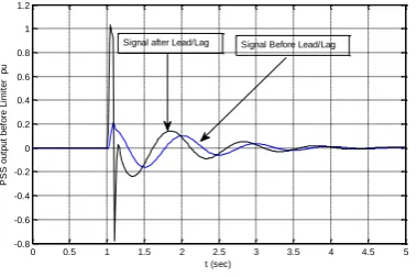
Fig.13 : Signals Before & After Lead/Lag PSS2A
Table I, The performance index of with and without PSS2A for Case (1):.
Controller Speed Deviation
With PSS2A 0.0015
Wthout PSS2A 0.018
From Fig . 5 to Fig. 13 demonstrate the superiority of the of machine with PSS2A with proposed tuning PSS over the machine without PSS2A both in the transient as well as the steady state periods. This superiority in performance is preserved under change in operating conditions (three cases).
Due to time lag produced by automatic voltage regulator time constant, the function of PSS is to compensate the phase lag by adding appropriate phase lead as shown in Fig. 14. To add damping, and produce a component of electrical torque in phase with speed variations [9]. Hence Fig. 14 shows the phase lead by (0.2 sec.) from phase lag,
VII. CONCLUSION
Power systems could loose synchronism and experience system separation if the low-frequency inter-area modes of oscillations are not damped efficiently. A conventional power system stabilizer can provide adequate damping for a limited range around its tuning point. To enhance the performance of power system stabilizer in Serir power plant, the power system stabilizer PSS2A out of service. Hence when the turbine subject to disturbance the generator oscillate and this oscillate not damped will. In this paper the authors put the PSS2A in service and sereach for optimal parameters . The use of a particle swarm optimization based algorithm has made it possible to tune the PSS2A parameters such that the summation of the square of the error (speed deviations) is minimized as in eq.(3).
Simulation results of the bench-mark problem of a single machine infinite bus system have confirmed the superiority of the machine with PSS2A stabilizer compared to the without PSS2A..
REFERENCES
[1]. P. Kundur " Power System Stability and Control' by McGraw-Hill, Inc, 1994.
[2]. Bixiang Tang "Parameter Tuning and Experimental Results of Power System Stabilizer" Msc Thesis, Louisiana State University and Agricultural and Mechanical College, 2011.
[3]. Ziad M. M. Ali " Power System Conventional Stabilizers & Automatic Voltage Regulator Gain Effects on torque coefficients " International Journal of Emerging Technology and Advanced Engineering, Volume 2, Issue 1, January 2012.
[4]. G.Y.Rajaa , S.Latha " Design of Power System Stabilizer for Power System Damping Improvement with Multiple Design Requirements" International Journal of Soft Computing and Engineering (IJSCE) ISSN: 2231-2307, Volume-2, Issue-5, November 2012.
[5]. Sayed M, Babak K and Mostafa A "Power system stabilizer tuning in multi machine electric power systems" Indian Journal of Science and Technology, Vol. 4 No. 12 Dec 2011.
[6] IEEE Recommended Practice for Excitation System Models for Power System Stability Studies, IEEE Standard 421.5-2005, April 2006.
[7]. Bixiang Tang"Parameter Tuning and Experimental Results of Power System Stabilizer" Thesis, Master of Science in Electrical Engineering, Louisiana State University, 2011
[8]. Eberhart, R. C. and Kennedy, J. A new optimizer using particle swarm theory" Proceedings of the Sixth International Symposium on Micromachine and Human Science, Nagoya, Japan. pp. 39-43, 1999.
[9]. Chaudhari Pooja b., Patel Milan v. "Design of Power System Stabilizer (PSS) to Enhance Power System Stability in Power System" International Journal of Engineering Research & Technology (IJERT), ISSN: 2278-0181, Vol. 5 Issue 03, March-2016
Appendix (A)
0 0.5 1 1.5 2 2.5 3 3.5 4 4.5 5 -0.8
-0.6 -0.4 -0.2 0 0.2 0.4 0.6 0.8 1 1.2
t (sec)
P
S
S
o
u
tp
u
t
b
e
fo
re
L
im
it
e
r
p
u
Fig. (2):Power System Stabilizer (PSS2A
Appendix (B)
PSS (PSS2A) parameters
Parameters Units Setting
𝑇𝑊1: 𝑇𝑊4 Washout filter time constant
Sec. 2.0 𝑇6 Input filter time
constant
Sec. 0.01 𝑇7 Input filter time
constant
Sec. 2.0
𝐾𝑆1 PSS gain pu 15
𝐾𝑆2 Signal scaling factor
pu 1
𝐾𝑆3 Signal matching factor
pu 0.133 𝑇1 Lead/Lag Time
constant
0.344
𝑇2 Lead/Lag Time
constant
0.182
𝑇3 Lead/Lag Time
constant
0.344
𝑇4 Lead/Lag Time
constant
0.182 𝑇8 Filter Time
constant
0 𝑇9 Filter Time
constant
0.01
M 5
N 1
𝑉𝑆𝑇𝑀𝐴𝑋 Upper limit of PSS
pu 0.1 𝑉𝑆𝑇𝑀𝐼𝑁 Lower limit of
PSS
pu -0.1
Appendix(C)
Static Excitation (ST1A) parameters
Parameters Units Setting
𝑉𝐼𝑀𝐴𝑋 Maximum input of regulator
pu 1.0
𝑉𝐼𝑀𝐼𝑁 Minmum input of regulator
pu -1.0
𝑇𝐵 Time constant for AVR transient
gain
Sec. 2.0
𝑇𝐶 Time constant for AVR transient
gain
pu 25
𝑇𝐵1 Time constant for AVR transient
gain
pu 1
𝑇𝐶1 Time constant for AVR transient
gain
pu 0.133
𝐾𝐴 AVR gain pu 20
𝑇𝐴 AVR time
constant
mSec. 1.8 𝑉𝐴𝑀𝐴𝑋 Maximum internal
signal
pu 7.90
𝑉𝐴𝑀𝐼𝑁 Minmum internal signal
pu -6.95
𝑉𝑅𝑀𝐴𝑋 Maximum output pu 7.90
𝑉𝑅𝑀𝐼𝑁 Minimum output pu -6.95
𝐾𝐹 Exciter
stabilizition gain
pu 0
𝑇𝐹 Exciter
stabilization time constant
pu 1
∆𝑃𝑎 2𝐻𝑠 ∆𝑃𝑚
2𝐻𝑠 ∆ω
∆𝑃𝑒
2𝐻𝑠
∆𝑃𝑒
Stabilizer gain & Phase compensator Ramp tracking filter
Highpass filtesrs
Lowpass filtesrs Highpass filtesrs
ω
𝑃𝑒
1
1 + 𝑆𝑇6 𝐾𝑆1
1 + 𝑆𝑇1 1 + 𝑆𝑇2 𝑆𝑇𝜔1
1 + 𝑆𝑇𝜔1
𝐾𝑆2 1 + 𝑆𝑇7 𝑆𝑇𝜔2
1 + 𝑆𝑇𝜔2
1 + 𝑆𝑇3 1 + 𝑆𝑇4
𝑆𝑇𝜔3 1 + 𝑆𝑇𝜔3
𝑆𝑇𝜔4 1 + 𝑆𝑇𝜔4
1 + 𝑆𝑇8 ሾ1 + 𝑆𝑇9ሿ𝑀
൨ 𝑁
𝐾𝑆3
𝑉𝑆