Jieqiong Lin, Xian Jing, Mingming Lu, Yan Gu, and Jinguo Han
Key Laboratory of Micro/Nano and Ultra-precision Manufacturing (Jilin Province), School of Mechatronic Engineering, Changchun University of Technology, Changchun 130012, China
Correspondence to:Mingming Lu (lumm@ccut.edu.cn)
Received: 26 January 2017 – Revised: 29 May 2017 – Accepted: 16 June 2017 – Published: 11 July 2017
Abstract. As always, the rapid wear of tools was one of the key factors limiting the precise turning of difficult-to-machine materials with diamond tool. 3-D elliptical vibration cutting has inherited many advantages of ellip-tical vibration cutting, such as the intermittent cutting property and friction reverse property. However, studies on the tool wear of three-dimensional elliptical vibration cutting has not been reported yet. The formation prin-ciple of 3-D cutting elliptical trajectory was analysed and a prediction model of tool wear was established in the present work. Besides, a self-developed three-dimensional elliptical vibration device was employed to conduct turning experiment. Compared with the proposed model, the experimental results showed a great agreement with the proposed prediction model. This work may provide a reference for the further optimization of the 3-D elliptical vibration cutting parameters.
1 Introduction
Since elliptical vibration cutting (EVC) was proposed by Shamoto and Moriwaki (1994), it has been considered as the most potential processing method and has received widespread attention of scholars. A large number of reports have shown that EVC has advantages over many aspects, such as improving the machinability of materials, suppress-ing the cuttsuppress-ing chatter, reducsuppress-ing cuttsuppress-ing force, extendsuppress-ing tool life and improving the surface uniformity (Jung et al., 2016; Zhou et al., 2016; Zhang et al., 2015, 2016; Li et al., 2015). To date, the studies on EVC are mainly focused on the fol-lowing aspects: (1) EVC devices, (2) machinability of dif-ferent materials, (3) EVC cutting force model, (4) tool wear condition.
According to the different driving methods of EVC de-vices, it can be divided into resonant type and non-resonant type. The resonant type of EVC machining device was de-veloped by E. Shamoto et al. and others (Moriwaki and Shamoto, 1995; Shamoto et al., 2002, 2005; Suzuki, et al., 2003). Driving signals with phase difference were utilized to excite its resonant mode, and an elliptical trajectory could be formed at the tool tip. The machining performance, cut-ting force model and tool wear resistance of hard and brittle materials were studied in their research. Besides, they
pro-posed a 3-D EVC device in 2005. Liu et al. (2004) started to study the resonant type EVC device in 2004. They studied the machinability, ductile-brittle transition model and the ef-fect of tool nose radius on cemented carbide using their pro-posed device (Ma et al., 2006; Nath et al., 2009a, b). Sathyan et al. studied the resonant EVC device and they also con-ducted some investigations on chip formation, vibration mark trace and tool wear during the machining process (Ahmed and Sathyan, 2010).
The first non-resonant EVC device was developed by Brehl et al. (1999) Aiming at obtaining the advantage of the developed non-resonant EVC device, they conducted some investigations on the maximum chip thickness, cutting force model, tool wear, and surface quality and so on (Brehl and Dow, 1999). Kim and Loh (2007) studied on non-resonant EVC device since 2007. PCD tool was used to carry out the cutting experiment. A series of structures, such as mi-cro grooves and the pyramid structure, were machined with various elliptical trajectory (Kim and Loh, 2007). In our pre-vious work, an improved memetic algorithm was proposed to achieve nonlinear identification for a 3-D EVC system (Lu et al., 2014).
ma-216 J. Lin et al.: 3-D elliptical vibration cutting
Figure 1.Principle of 2-D EVC.
terials, aiming to achieve the best cutting performances of EVC. The mechanism of 3-D EVC to further improve the tool life has not been reported. In this paper, the reasons for the reduction of tool wear in 3-D EVC are analysed based on the self-developed non-resonant 3-D EVC device. The main structure of this paper is as follows: the principle of 3-D EVC is introduced in Sect.2. Section 3 describes the reduction of tool wear model in 3-D EVC. Section 4 verifies the proposed tool wear model through the experiments.
2 Principle of 3-D EVC
3-D EVC is developed from conventional EVC. The remark-able characteristics of EVC are intermittent cutting proper-ties and friction reversal compared with traditional machin-ing. The principle of EVC is shown in Fig. 1,a andbis the semi-major axis and semi-minor axis, respectively. Tool edge is perpendicular to the workpiece.aprepresents the nominal
depth of cut,Vcis cutting speed which is generally less than
the maximum vibration speed. The tool tip is moving with an ellipse trajectory in XOY plane. As shown in Fig. 1, tool (1) to tool (6) donate to six representative positions of tool tip motion along the elliptical trajectory. Point A is the starting point of one vibration cycle, point B is the bottom of the el-liptical trajectory, point C is a critical point where tool start to separate from workpiece, and point D is the starting point of next cycle. The maximum depth of cut and friction reversal occurred at the duration from point B to point C.
Elliptical vibration cutting has a limitation to turn the com-plex surfaces. So the 3-D EVC was proposed to address this problem. The principle of 3-D EVC is shown in Fig. 2, ellipse 1 is the projection of tool trajectory on plane YOZ. Take the long axis of ellipse 1 as a rotation axis, the ellipse 2 can be obtained by ellipse 1 rotates aβ angle. The projection of el-lipse 2 on plane XOY and YOZ both are elel-lipses. And the projection of ellipse 2 on plane XOZ is a straight line. Take the short axis of ellipse 1 as a rotation axis, the ellipse 3 can be obtained by ellipse 1 rotates aαangle. The projection of ellipse 3 on plane YOZ and XOZ both are ellipses. The ellip-tical motion trajectory of arbitrary position can be obtained by adjusting the value of angleα andβ. In addition, angle
Figure 2.The tool trajectory of 3-D EVC.
Figure 3.Wear regions of elliptical vibration cutting.
αandβ are two important parameters during the modelling process.
3 Tool wear predictive model of 3-D EVC
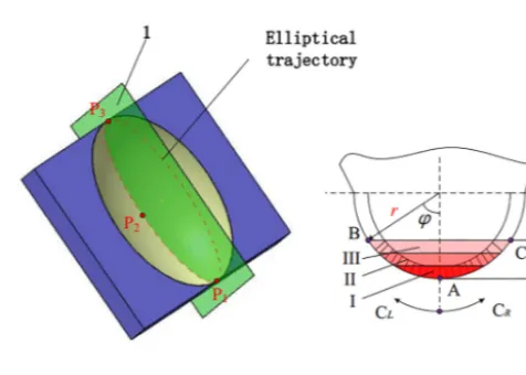
Before the prediction model of tool wear is proposed, it is necessary to introduce the tool wear condition during the el-liptical vibration cutting. As shown in Fig. 3a, tool tip pass the point P1, P2 and P3. At point P2, tool tip reaches the maximum depth of cutap. The value of contact area between
tool and workpiece is the maximum at this moment. It is assumed that the vibration period of one elliptical vibration cutting isT. Then the contact time of tool and workpiece is t=apT /(2a). In this paper, we take it as a severe wear zone
when tool tip contact with workpiece at time 2t /3, t
, and marked it as region I. Similarly, we take it as a moderate wear zone and mild wear zone when tool tip contact with work-piece at time
t /3,2t /3
and time 0, t /3
Figure 4.Diagrams of vibration tool trajectory of 3-D EVC and shift of contact marginal points.
Table 1.Machining conditions.
Parameters Value
Tool material PCD
Tool rake angle (deg) 0 Tool clearance angle (deg) 11 Tool nose radius (mm) 0.2
Workpiece material Aluminum, brass Feed rate (µm rev−1) 5
Depth of cut (µm) 4 Rotational speed 15, 30, 45 of Spindle (rev min−1)
Vibration amplitude (µm) 4×4×4 (o-xyz), 4×4 (o-yz)
to both sides with the increasing of depth of cut. When the depth of cut reaches the maximum valueap, point B and C
become the contact marginal points. We useCLandCR rep-resent the direction and speed when contact marginal points shift to both sides, respectively.
Tool wear speed reduces to a large extent due to the in-terrupted cutting characteristic of elliptical vibration cutting. However, tool wear of region I also will affect the cutting accuracy during cutting process. The vibration tool trajec-tory of 3-D EVC and the shift of contact marginal points are shown in Fig. 4.
Figure 5.Cutting experiment of 3-D EVC.
As shown in Fig. 4a, the 3-D ellipse trajectory can be ob-tained by the 2-D ellipse trajectory by a shift of angleαand β. Point P1, P3are donate to the cut in point and cut out point,
respectively. Point P2is the tool tip position relative to
218 J. Lin et al.: 3-D elliptical vibration cutting
Figure 6.SEM micrographs of tool wear.(a)SEM micrographs of tool using 2-D EVC. (I) Top view of tool tip. (II) Partial enlarged detail of tool tip. (III) Front view of tool.(b)SEM micrographs of tool using 3-D EVC. (I) Top view of tool tip. (II) Partial enlarged detail of tool tip. (III) Front view of tool.
of tool wear locates at the right side of tool nose arc when α >0. On the contrary, the region of tool wear located at the left side of tool nose arc whenα <0. We assume that positive clockwise and negative anti-clockwise. Angleβ mainly af-fects the shift speed of contact marginal points between tool and workpiece and the region of tool wear. Thus angleαand β have significant influences on tool wear conditions of 3-D EVC.
It is assumed that the tool vibration frequency of 3-D EVC isf. Then the tool vibration period isT =1/f. The time to reach the maximum depth of cut isT ap/(2b) during cutting.
The wrap angle of the maximum tool wear on the one side of tool tip can be obtained as follows:
ϕ=arccos r−a
p
r
(1)
On the basis of the arc length formulae L=ϕr, the shift speed of contact marginal points between tool and workpiece can be obtained as follows:
CL= 2bL
T ap = 2br
T ap
arccos r−a
p
r
(2)
Within the same time T ap/(2b), the moving distance of
the contact arc central point between tool and workpiece is L0=βr. Then the shift speed of the contact arc central point between tool and workpiece can be expressed as follows,
TL= 2bβr
T ap
(3)
We analyzed the various tool wear region of 3-D EVC from the following three cases whenα <0.
WhenTL=CL,β=ϕ=arccos r−ap/r. The
mov-ing speed of the contact arc central point between tool and workpiece is equal to the shift speed of the contact marginal points. That means the contact arc central point A is coin-cide with the contact marginal point C of right side as shown in Fig. 4b. The contact marginal point B of left side is mov-ing at speed of 2TL. The tool wear zone was divided into three regions according to the time of tool tip contact with the workpiece. The region
0,2β/3
of the left side of tool tip is the severe wear region I. The region
2β/3,3,4β/3 is the moderate wear region II, and4β/3,2βis the mild wear region III.
WhenTL> CL,β > ϕ=arccos
r−ap
/r. The mov-ing speed of the contact arc central point between tool and workpiece is larger than the shift speed of the con-tact marginal points. That means the concon-tact marginal point C of right side is shifting to the left slowly from the tool arc central point. The moving speed isTL−CL. The mov-ing speed of the contact marginal point B of left side to the left is TL+CL. As shown in Fig. 4c, the contact marginal point C of right side is located at the left of tool tip when tool reaches to the maximum depth of cut ap. The central angle is β−ϕ at this moment. The tool
marginal points. That means the contact marginal point C of right side is shifting to the right slowly from the tool arc central point. The moving speed is CL−TL. The moving speed of the contact marginal point B of left side to the left is TL+CL. As shown in Fig. 4c, the contact marginal point C of right side is located at the left of tool tip when tool reaches to the maximum depth of cutap. The central angle isϕ−β
at this moment. The tool wear zone is divided into three re-gions according to the time of tool tip contact with the work-piece. The region
0,(β+ϕ)/3
on the left side of the tool tip and region
0,(ϕ−β)/3
on the right side of the tool tip formed region I. The region
(β+ϕ)/3,2β+2ϕ/3 on the left side of the tool tip and region(ϕ−β)/3,(2ϕ−2β)/3 on the right side of the tool tip formed region II. Similarly, the region (2β+2ϕ)/3, β+ϕon the left side of tool tip and region(2ϕ−2β)/3, ϕ−βon the right side of tool tip formed region III. The contact arc central point A is located at severe wear region I.
From the three different tool wear conditions shown in Fig. 4b to d, it can be seen that the tool wear can be fur-ther reduced by adjusting the cutting parameters during 3-D EVC process compared with the traditional EVC. The veri-fied experiment is shown in Sect. 4.
4 Results and discussion
In this paper, a self-developed 3-D EVC device was used to carry out the cutting experiment (Lin et al, 2016). The exper-iment was carried out on the SPINNER precision lathe. The machining parameters are shown in Table 1. The machining system is shown in Fig. 5.
The tool vibration frequency used in the experiment is f =100 Hz. Besides, α=45◦, β=30◦. According to the prediction model of tool wear, we can know that the most se-rious regions of tool wear for 3-D EVC is located at the left side of tool tip (from front view), which is consistent with the wear condition of Fig. 4d. In this paper, a 2-D EVC exper-iment was also carried out to offer a comparison. The mea-surement of tool wear was based on a same cutting distance of workpiece in our experiment. Fifteen workpieces with a diameter of 10mm are cut at end faces. The cutting results were compared. As shown in Fig. 6, the regions of tool wear for 2-D EVC are asymmetrically distributed on the both sides
5 Conclusions
In this paper, a tool wear prediction model was proposed for 3-D EVC. The arc of diamond tool tip was divided into three regions by analysis of the 3-D EVC diamond tool moving mechanism based on the various conditions of the lowest point of tool arc and contact marginal points between tool and workpiece during 3-D EVC cutting. The model was used to predict the tool wear conditions by adjusting the cutting parameters. At last, the tool wear prediction model was ver-ified by experiments. The results indicate that the proposed model is feasible to predict the tool wear of 3-D EVC, which provide theoretical basis for cutting parameters optimization to further extend the tool life.
Data availability. All the data used in this manuscript can be ob-tained by requesting from the corresponding author.
Competing interests. The authors declare that they have no con-flict of interest.
Acknowledgements. This research was financially supported by the Ministry of Science and Technology State Key Support Pro-gram (2016YFE0105100), National Natural Science Foundation of China (NSFC) (51375060), Micro-Nano and Ultra-Precision Key Laboratory of Jilin Province (20140622008JC) and Sci-ence and Technology Development Projects of Jilin Province (20160520072JH).
Edited by: Bahman Azarhoushang Reviewed by: two anonymous referees
References
Ahmed, S. A. and Sathyan, S.: Experimental investigation of trans-verse vibration-assisted orthogonal cutting of AL-2024, Int. J. Mach. Tool. Manu., 50, 294–302, 2010.
220 J. Lin et al.: 3-D elliptical vibration cutting
Jung, H., Hayasaka, T., and Shamoto, E.: Mechanism and suppres-sion of frictional chatter in high-efficiency elliptical vibration cutting, CIRP Ann.-Manuf. Techn., 65, 369–372, 2016. Kim, G. D. and Loh, B. G.: Characteristics of chip formation in
mi-cro V-grooving using elliptical vibration cutting, J. Mimi-cromech. Microeng., 17, 1458–1466, 2007.
Li, W., Lin, F., and Zhang, D.: Study on the improvement of surface quality through ultrasonic elliptical vibration cutting, Advances in Future Manufacturing Engineering: Proceedings of the 2014 International Conference on Future Manufacturing Engineering (ICFME 2014), Hong Kong, 10–11 December 2014, CRC Press, 2, 269–279, 2015.
Lin, J., Lu, M., and Zhou, X.: Development of a Non-Resonant 3-D Elliptical Vibration Cutting Apparatus for 3-Diamond Turning, Exp. Techniques, 40, 173–183, 2016.
Liu, K., Li, X. P., Rahman, M., and Liu, X. D.: Study of ductile mode cutting in grooving of tungsten carbide with and with-out ultrasonic vibration assistance, Int. J. Adv. Manuf. Tech, 24, 389–394, 2004.
Lu, M., Zhou, X., and Lin, J.: Improved Memetic Algorithm for Nonlinear Identification of a 3-D Elliptical Vibration Cutting System, P. I. Mech. Eng. I-J. Sys., 228, 449–460, 2014. Ma, C. X., Shamoto, E., Xu, L. M., Liu, N., and Moriwaki, T.:
Ultra-Precision Cutting of Brittle Materials with Ultrasonic Vibrated Diamond Tool[C], Materials Science Forum, Trans Tech Publi-cations, 532, 169–172, 2006.
Moriwaki, T. and Shamoto, E.: Ultrasonic elliptical vibration cut-ting, CIRP Ann.-Manuf. Techn., 44, 31–34, 1995.
Nath, C., Rahman, M., and Neo, K. S.: Machinability study of tung-sten carbide using PCD tools under ultrasonic elliptical vibration cutting, Int. J. Mach. Tool. Manu., 49, 1089–1095, 2009a.
Nath, C., Rahman, M., and Neo, K. S.: A study on the effect of tool nose radius in ultrasonic elliptical vibration cutting of tungsten carbide, J. Mater. Process. Tech., 209, 5830–5836, 2009b. Shamoto, E. and Moriwaki, T.: Study on Elliptical Vibration
Cut-ting, CIRP Ann.-Manuf. Techn., 43, 38–43, 1994.
Shamoto, E., Suzuki, N., Moriwaki, T., and Naoi, Y.: Development of ultrasonic elliptical vibration controller for elliptical vibration cutting, CIRP Ann.-Manuf. Techn., 51, 327–330, 2002. Shamoto, E., Suzuki, N., Tsuchiya, E., Hori, Y, Inagaki, H., and
Yoshino, K.: Development of 3 DOF ultrasonic vibration tool for elliptical vibration cutting of sculptured surfaces, CIRP Ann.-Manuf. Techn., 54, 321–324, 2005.
Suzuki, N., Nakamura, A., Shamoto, E., and Harada, K.: Ultrapre-cision micromachining of hardened steel by applying ultrasonic elliptical vibration cutting [C], Micromechatronics and Human Science, 2003, MHS 2003, Proceedings of 2003 International Symposium on. IEEE, 221–226, 2003.
Zhang, C., Ehmann, K., and Li, Y.: Analysis of cutting forces in the ultrasonic elliptical vibration-assisted micro-groove turning process, Int. J. Adv. Manuf. Tech., 78, 139–152, 2015.
Zhang, J., Cui, T., Ge, C., Sui, Y., and Yang, H.: Review of mi-cro/nano machining by utilizing elliptical vibration cutting, Int. J. Mach. Tool. Manu., 106, 109–126, 2016.