Application of the Direct Displacement Based Design Methodology
for Different Types of RC Structural Systems
Saleh Malekpour
1), and Farhad Dashti
2),*
(Received August 6, 2012, Accepted April 4, 2013)
Abstract: This study investigates the direct displacement based design (DDBD) approach for different types of reinforced concrete structural systems including single moment-resisting, dual wall-frame and dual steel-braced systems. In this methodology, the displacement profile is calculated and the equivalent single degree of freedom system is then modeled considering the damping characteristics of each member. Having calculated the effective period and secant stiffness of the structure, the base shear is obtained, based on which the design process can be carried out. For each system three frames are designed using DDBD approach. The frames are then analyzed using nonlinear time-history analysis with 7 earthquake accelerograms and the damage index is investigated through lateral drift profile of the models. Results of the analyses and comparison of the nonlinear time-history analysis results indicate efficiency of the DDBD approach for different reinforced concrete structural systems.
Keywords:direct displacement based design, RC frame systems, time-history analysis, accelerograms.
1. Introduction
In recent years, there has been a great tendency toward performance-based seismic design of structures. In this con-nection, various methods have been developed among which Capacity Spectrum Method (Freeman1998), the N-2 Method (Fajfar2000), and Direct Displacement-Based Design can be enumerated. A relatively new performance-based seismic design procedure called the direct displacement-based design (DDBD) proposed by Priestley and Kowalsky (2000) has recently received notable acceptance among researchers. It seems that the methods could be a rational alternative to tra-ditional erroneous force-based seismic design of structures. The method defines the design performance level of the structure in terms of displacement limits. Therefore, dis-placement is the key parameter of the design method.
This paper investigates the DDBD of different types of reinforced concrete structural systems including single moment-resisting, dual wall-frame and dual steel-braced systems. There is a need for a design methodology that is applicable to dual system structures, because the dynamic
behaviour of dual systems is considerably different from pure frame or wall or steel braced structures for which many design recommendations already exist. Such differences in dynamic behaviour are attributed principally to the interaction that takes place between different structural systems, which is not well accounted for in current design practice.
A further motivation for this study comes from the fact that combination of different structural systems results in an effi-cient earthquake-resisting system, and considering structural and aesthetic points of view combination of the structural systems presents considerable advantage over structures formed purely out of frames or walls or bracing systems.
The displacement based design of RC structures has been addressed increasingly in recent years, and the displacement based design of multiple degree of freedom RC structures has been the main philosophy of these approaches. Gulkan and Sozen (1974) investigated the nonlinear behavior of RC structures under dynamic loads, and presented equivalent equations for damping of single degree of freedom structures. Shibata and Sozen (1976) presented the substitute structure methodology for RC structures, and intended to devise a dis-placement based design method. Moehle (1992) suggested the general outline of a seismic resistant design approach based on the inter-story relative displacement calculation using dis-placement response spectrum. Although the initial step of design using this approach is also calculation of stiffness, elastic time period and different strengths of the structure, it is quite different from the traditional methods as includes direct control of displacements instead of indirect control using ductility coefficients. The initial step of the approach recom-mended by Kowalsky et al. (1995) for single degree of free-dom structures is determination of the maximum target displacement which can be obtained based on the ductility
1)
Department of Structural Engineering, School of Civil Engineering, University of Tabriz, 51664 Tabriz, Iran. 2)Department of Civil and Natural Resources
Engineering, University of Canterbury, Christchurch 8140, New Zealand. *Corresponding Author; E-mail: [email protected]
CopyrightThe Author(s) 2013. This article is published with open access at Springerlink.com
International Journal of Concrete Structures and Materials Vol.7, No.2, pp.135–153, June 2013
capacity being proportional to details of the members. Assuming an acceptable value for yield displacement, the designer converts the maximum displacement to the demand displacement ductility, and using a series of displacement response spectrums with different damping values (due to ductility values), calculates the effective period of the single degree of freedom structure in the maximum displacement. The ultimate results of the calculated yield strength based on the maximum displacement and secant stiffness is corre-sponding to the effective period. Calvi and Kingsley (1995), and Calvi and Pavese (1995) generalized this approach for the structures with multiple degrees of freedom. It should be noted that the ultimate results of all these approaches are the demand strength values based on which sections and dimensions of the members shall be computed.
In recent years, new approaches have been proposed which use different methodologies. Fardis et al. (1997) presented an approach based on the ultimate state design for gravity loads and displacement control under the service level characteristics. Chopra and Goel (2001) presented the application procedure of the inelastic design spectrum in DDBD. Assuming an initial displacement profile, Priestley and Kowalsky (2000) suggested a general design procedure for RC structures, following which Sullivan et al. (2006) developed the DDBD method for RC frame-wall structures. Sullivan et al. (2005) investigated a trial methodology which provided encouraging results when applied to regular frame-wall structures in which the frames were parallel to the walls. The research identified that the fol-lowing two tasks were required to improve the accuracy of the methodology and thereby enable the Direct DBD (Priestley 2003) approach to be used for frame-wall structures:
• Development of an expression for the displaced shape of frame-wall structures at maximum response, to enable equivalent SDOF characteristics to be established. • Development of an expression for the equivalent SDOF
system ductility or equivalent viscous damping that takes into account the frame-wall interaction.
Sullivan et al. (2005) proposed that the design displacement profile be set as a function of the moment profile in the walls, using proportions of strength assigned at the start of the design procedure. There is experimental evidence that supports the validity of this approach as reported by Sullivan et al. (2004). Another recommendation made by Sullivan et al. (2005) was that the equivalent SDOF system viscous damping could be obtained by factoring the individual frame and wall compo-nents by the proportions of overturning they resist. The chal-lenge in this paper is therefore to finalize the design procedure proposed by Sullivan et al. (2005) and to verify its accuracy through examination of a range of case study structures.
Belleri (2009) suggested the performance based design approach for RC precast buildings in 2009. Sullivan et al. (2009) investigated a DDBD code in 2009. Garcia et al. (2010) investigated the DDBD approach for steel frame-RC wall dual systems in 2009. Pennucci et al. (2009) studied the DBD for RC precast wall-damper systems.
RC buildings with steel bracings are the new structural systems addressed in rehabilitation of RC structures in recent
years and researches are extensively investigating on appli-cation of steel bracing systems in such buildings. The research conducted by Higashi et al. (1981) on application of CBF and EBF bracing systems in rehabilitation of RC frames and the studies of Badox and Jirsa (1990) on non-linear behavior modeling of bracing systems in RC frames can be cited as examples. Maheri and Sabahi (1997) sug-gested the direct connection of the internal bracing to the RC frame. Tasnimi and Masoomi (1999) experimentally inves-tigated the direct use of steel bracings in RC frames. For this purpose, the manufactured frames were subjected to static gravity loads and cyclic lateral loads. The results indicated that adding bracing to an RC frame, depending on the uti-lized details, considerably increases the equivalent stiffness of the frame and leads to notable change in its behavior. Ghaffarzadeh and Maheri (2006a, b) showed that different directly connected internal bracing systems can be used effectively in retrofitting of the existing concrete frames as well as shear resisting elements for the construction of new RC structures. Having conducted two cyclic experiments on an RC moment-resisting frame and an RC frame with steel bracings, Youssef et al. (2007) came to the conclusion that the braced frame has more ductility and can resist greater lateral load. Maheri and Ghaffarzadeh (2008) investigated the amount of the interaction force between the RC frame and the steel bracing analytically and experimentally using the experiments conducted on RC moment resisting frames and RC frames with steel bracings. Malekpour et al. (2012) developed steps of the Displacement Based Design method for RC frames with steel bracings.
In this study, considering the ever increasing development of the DDBD and its use in RC buildings, the DDBD methodology is investigated for three lateral load resisting systems of reinforced concrete structures, i.e., RC Frame, RC Wall-Frame and Steel-Braced RC Frame Systems. For this purpose, the displacement profile is calculated and the equivalent single degree of freedom system is then modeled considering the damping characteristics of each member. Having calculated the effective period and secant stiffness of the structure, the base shear is obtained, based on which the design process can be carried out. For each system three frames are designed using DDBD approach. The frames are then analyzed using nonlinear time-history analysis with 7 earthquake accelerograms and the damage index is investi-gated through lateral drift profile of the models. Results of the analyses and comparison of the nonlinear time-history analysis results indicate efficiency of the DDBD approach for different reinforced concrete structural systems located in near-field regions.
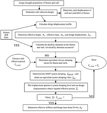
2. Description of the Design Procedure
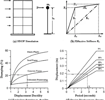
stiffness (Ke) at maximum response (Fig.1b), equivalent viscous damping including both the viscous and hysteretic dampings inherent in the real structure, and an effective mass (me) and height (Fig.1a). Also, a set of equations define the mathematical relationship between displacement ductility and damping and a set of design displacement spectra have been used throughout the design process.
Assuming a design ductility, which is choosed by the designer based on ultimate design displacement and yield displacement of the real structure aslD=DD/Dy, or simply based on code requirements, and using existing ductility-damping diagrams, a design ductility-damping is selected for the equivalent SDOF system (Fig.1c). Then, a design period is obtained using Fig.1d and according to the specified design displacement and the specified equivalent viscous damping.
2.1 Assignment of Strength Proportions for Dual Systems
In order to develop the equivalent SDOF structure, strength proportions are assigned, by which the shear and moment profiles in the braces and shear walls can be established. The story shear above the base of the walls and bracings cannot be obtained directly from the design base shear. As such, wall shears and bracing shears are obtained as the difference between the total shear and the frame shear as shown in Eqs.
(1a) and (1b). Recall that the frame story shear can be deter-mined since it is dependent only on the strength of the beams up the building height (Sullivan et al.2006).
Vi;brace
Vb
¼Vi;total
Vb
Vi;frame
Vb
ð1aÞ
Vi;wall
Vb
¼Vi;total
Vb
Vi;frame
Vb
ð1bÞ
where,Vbis the total base shear,Vi,braceis the bracing shear at leveli,Vi,wallis the wall shear at level iand Vi,total is the total shear at leveli, andVi,frameis the frame shear at leveli. For the purpose of establishing the inflection height, a triangular distribution of the fundamental mode inertia forces along the height of the structure is assumed. This approxi-mation enables the total storey shear to be obtained as a function of the base shear as shown in Eq. (2) (Sullivan et al. 2006).
Vi;total
Vb
¼1 iði1Þ
nðnþ1Þ ð2Þ
whereVi,totalis the total shear at leveli,Vbis the total base shear, and n is the total number of stories in the building. Assuming that beam moments are carried equally by
columns above and below a beam-column joint, the frame storey shear is obtained as a function of the beam strength using Eq. (3) (Sullivan et al.2006).
Vi;frame ¼ P
Mb;iþPMb;i1
2ðhihi1Þ ¼
P
Mb;i
hcol
ð3Þ
where,Vi,frameis the frame shear at level i,Mb,iis the beam moment at level i, and hcol is the inter-storey height. Although the beam strengths are not actually known to begin with, Eq. (3) is useful as it indicates that provided beams of equal strength are to be used, thus the frame storey shear is constant along the building height. Consequently, if 40 % of the base shear is being carried by the frames, this 40 %Vb will be carried along the entire height of the frame. As such, the shear proportion carried by the frame can be substituted in Eqs. (1a) and (1b) and the brace shears and bending can be calculated, all as a function of the design base shear (Ghorbani-Asl2007).
2.2 Yield Deformation and Design Displacement Profile of Frames, Bracings and Walls
The ductility demands of the frames at level i can be obtained using Eq. (4).
lframe;i¼
DiDi1
hihi1
1 hyframe
ð4Þ
where,lframe,iis the frame ductility at leveli, andhyframeis the yield drift of the frame (from Eq. (5) (Priestley2003)).
hyframe¼ 0:5lbey
hb
ð5Þ
where Di, Di-1, hi, and hi-1, are the displacements and
heights at leveliand leveli-1, respectively.
The design displacement profile is developed using the various values obtained as the following for each of the systems, together with the design story drift using Eqs. (6) to (13).
For RC frame models:
n4: Di¼hdhi ð6aÞ
n4: Di¼hdhi 10:25
hi
hn
ð6bÞ
In Eq. (6), hd is design story drift, hi is the i-th story height, and n is the number of stories. It has been suggested by Pettinga and Priestley (2005) that theDibe multiplied by a reduction factor of 0.85. In this study, this factor was found to be effective and therefore was included in calculating story design displacement. The design inter-story drift (hd) was considered to be 2.5 % for this study
Dy¼0:5ey
lb
hb
ð0:6hmÞ ð7Þ
In Eq. (7),ey,lb,hbandhmare yield strain of longitudinal bars, bay length, beam height and effective height of the
structures (which can be assumed to be 0.7 hn for framed structures), respectively.
For RC wall-frame models:
Di¼Diyþ hd
/ywall hinf 2
hi ð8Þ
The displacement profile of the structure at yield of the wall, Diy, can then be established using the wall yield curvature, inflection height and storey height in accordance with Eq. (9a,9b).
Diy ¼
/yWallhinfhi
2
/yWallðhinfÞ2
6 for hihinf ð9aÞ
Diy ¼
/yWallh2 i
2
/yWallh3 i 6hinf
for hi\hinf ð9bÞ
The yield curvature of the walls,/yWall, is firstly obtained using Eq. (10) (Priestley2003).
/ywall¼2ey
Lw
ð10Þ
whereeyis the yield strain of the longitudinal reinforcement in the wall andLw is the wall length.
hdis the design storey drift, andhiis the height at leveli. Note that the design story drift can be initially taken as the code limit for non-structural damage, reduced to allow for higher mode effects in accordance with Eq. (11).
hd¼hd;limit 1
ðN5Þ 100
MOT;frame
MOT;total þ0:25
hd;limit
ð11Þ
whereNis the number of stories, MOT, frame is the over-turning resistance of the frame and MOT, total is the total overturning resistance of the structure. This approximate equation was proposed after reviewing the results of initial trial case studies (Sullivan et al.2006). As mentioned before, the ratio of frame to total overturning resistance can be obtained in terms of the base shear using the strength assignments made at the start of the design procedure.
For Steel braced RC frame models:
Di¼Diyþ ðhdÞ hi ð12Þ
The yield deformation of bracing is calculated using Eq. (13) (Ghorbani-Asl 2007).
Dyi¼
FyLbri
Ecoshi
ð13Þ
2.3 Equivalent SDOF Characteristics
With knowledge of the displacement profile at maximum response;Di, the seismic masses;mi, and storey heights;hi, the equivalent SDOF design displacement; Dd, effective mass; me, and effective height; he, can be calculated as shown in Eqs. (14–16) (Sullivan et al.2004), respectively.
Dd¼
Pn
i¼1ðmiD2iÞ
Pn
i¼1ðmiDiÞ
ð14Þ
me¼
Pn
i¼1ðmiDiÞ Dd
ð15Þ
he¼
Pn
i¼1ðmiDihiÞ
Pn
i¼1ðmiDiÞ
ð16Þ
2.4 Determine the Design Base Shear
and Member Strengths
With the effective period established, the effective stiff-ness,Ke, is determined in accordance with Eq. (17).
ke¼4p2
me
T2 e
ð17Þ
wheremeis the effective mass (from Eq. (15)) andTeis the effective period. This effective stiffness is then multiplied by the design displacement,Dd, to obtain the base shear,Vb, as shown by Eq. (18).
Vb¼KeDd: ð18Þ
Individual member strengths are then determined maintaining the strength proportions assigned at the start of the design process. Note however that rather than using a triangular lateral force distribution, better results are obtained distributing the base shear along the height of the structure according to Eq. (19).
Fi¼
miDi
PN
i¼1miDi
Vb; ð19Þ
where,Fiis the portion of base shear applied at leveli,miis the mass at leveli, andDithe displacement at level i.
2.5 Equivalent Viscous Damping
One of the most important parameters required for DDBD approach is equivalent viscous damping. Thus, in this sec-tion the methodology used for calculasec-tion of this parameter is given for the structural systems investigated in this study. Equivalent viscous damping is a function of ductility and the effective period (Malekpour et al. 2012; Priestley and Grant2005; Blandon2004).
When beams of equal strength are used along the height of the structure, the ductility obtained from Eq. (4) for each story can be averaged to give the frame displacement duc-tility demand. The proposed procedure determines the equivalent damping in such a way that when this damping is applied to a SDOF system with a definite effective period which is obtained based on the secant stiffness in the max-imum displacement response, response of this SDOF system
becomes consistent with the nonlinear time-history analysis response. Finally, the objective is to propose an equation that calculates the equivalent damping factor for DDBD. In order to obtain the equivalent damping, the following method which is based on Blandon‘s method (Blandon 2004) is used.
The process is repeated for effective periods from 0.5 to 4 s each 0.5 s, for 5 ductility levels from 2 to 6. Six different hysteretic curves are used and all the cases are analyzed for six records.
Step 1: Initially, an effective period (Teff) and a ductility level (l) are selected.
Te;trial¼
N
6 ffiffiffiffiffiffiffi lsys
p ð20Þ
whereNis the total number of stories andlsysis the system ductility.
Step 2: The equivalent damping factornis estimated. For the first iteration this was based on Jacobsen’s approach (Jacobsen1930) according to the hysteretic loop considered. However, after the results of the first iteration were obtained, the equivalent damping was changed in the next iterations to improve the substitute structure/time-history agreement. The significant assumption of this step would be definition of the initial viscous damping factorn0which is assumed equal to zero to prevent its effect.
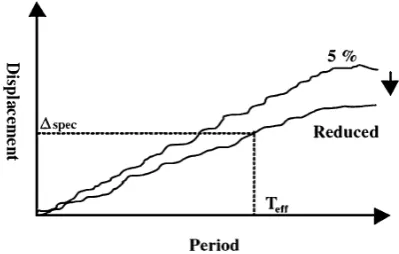
Step 3: The average damped displacement spectrum is determined, as shown in Fig.2.
Step 4: An initial response displacement (Dspec) is obtained from the actual average damped spectrum (non-smoothed) for the selected effective periodTeff, as shown in Fig.2.
Step 5: For a given hysteretic model, the initial stiffness (Kini) and yielding force (Fy) are defined usingDspec, mass (meff), effective period (Teff) and the ductility (l) as follows:
Dy¼Dspec
l ð21Þ
keff ¼ 4p2m
eff
T2 eff
; Fmax¼keff Dspec ð22Þ
The yield force Fy can be found from the ductility and maximum response force using hysteretic-model-specific equations. The initial stiffnessKinican then be computed as:
Kini¼
Fy
Dy ð23Þ
Step 6: Time-history analysis is run for each of the records and the maximum displacements are obtained.
Step 7: The displacements obtained from Step 6 are compared with that from Step 4.
Step 8: If the displacements are similar (within a tolerance of 3 %), the damping factor is not changed and the process is repeated from Step 1 with the nextTeffandl; otherwise, the damping factor is modified and the process is repeated from Step 2.
Using Eq. (24), the equivalent damping parameters can be calculated (Priestley and Grant2005).
nhyst;frame¼ 120 1:3p 1
1 l0:5 frame
0:1rlframe !
1þ 1
ðTe:trialþ0:85Þ4 !
ð24Þ
where r is the post-elastic stiffness coefficient, typically taken as 0.05 for new RC structures. Damping for the equivalent SDOF system is determined using Eq. (25) (Priestley and Grant2005).
nSDOF¼nhyst;frame ð25Þ
For RC wall fram, wall equivalent viscous damping components are calculated using Eq. (26)
nhyst;wall¼ 95 1:3p 1
1 l0:5
wall
0:1rlwall
1þ 1
ðTe;trialþ0:85Þ4 !
ð26Þ
The equivalent viscous damping for equivalent SDOF system is determined using Eq. (27) (Priestley and Grant 2005).
nSDOF¼
MwallnwallþMOT;framenframe
MwallþMOT;frame
ð27Þ
where,MOT,frame is the overturning resistance of the frames andMbraceis the overturning resistance (flexural strength) of the braces.
Note:fframe is calculated using Eq. (24)
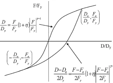
For Steel braced RC frame models, the constitutive model considered for the steel bracing to calculate the equivalent viscous damping is Ramberg–Osgood model, and the load-ing curve complies with Eq. (28) (Blandon2004).
D Dy
¼ F
Fy
1þ F0
Fy y1!
ð28Þ
Finally, Blandon proposed the EVDF for six different constitutive models using statistical approaches and the equations are presented in Eq. (29).
nbrace¼
a
p 1 1 lb
1þ 1 ðTþcÞd
! 1
N ð29aÞ
N ¼1þ 1
ð0:5þcÞd ð29bÞ
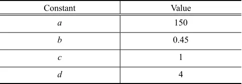
wherea,b, care the constant coefficients defined for each hysteresis model and are given in Table1,lis the ductility factor, T is the effective period, and N is the normalization factor and the model considered in this study is Ramberg– Osgood model.
The equivalent viscous damping for equivalent SDOF system is determined using Eq. (30) (Malekpour et al.2012).
nSDOF¼MbracefbraceþMOT;framenframe
MbraceþMOT;frame
ð30Þ
Note:fframe is calculated using Eq. (24).
At this point of the design process, the equivalent viscous damping has been established for the systems being inves-tigated and as such, the displacement spectrum is developed at the design level of damping. This can be done using a damping-dependent scaling factor appropriate for the seis-mological characteristics of the design region. CEN (1998) recommends that thegvalue obtained from Eq. (31) be used to scale the elastic spectrum to the damping level of interest.
g¼ ffiffiffiffiffiffiffiffiffiffiffiffiffiffiffiffiffiffiffiffiffiffiffiffiffiffiffiffiffiffiffi10=ð5þnSDOFÞ p
0:55 ð31Þ
where,nSDOFis the equivalent viscous damping of the sys-tem as given by Eqs. (25), (27), and (30). The design dis-placement is then used to read (or interpolate between known points) the required effective period,Te, as shown in Fig.2.
The spectral values of all the other damping values, excluding damping 5 %, with modification factor of EC8 CEN (1998) is obtained as Eq. (32).
DðT;nÞ ¼DðT;5Þ 10 5þn
1
2
ð32Þ
where, n is the structure damping and is expressed as a percentage of the critical damping for the considered design limits.
The effective period obtained from Fig.2 is compared with the initial period. If this period does not agree with the
Table 1 Constants of Ramberg–Osgood hysteresis model.
Constant Value
a 150
b 0.45
c 1
initial period, replaces the initial period and the process is repeated. When the effective period agrees with the initial period, it will be the design period and will be used for obtaining the design base shear.
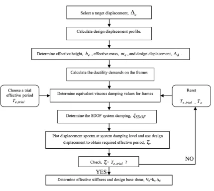
2.6 Design Flowcharts
In this section the DDBD methodology employed for the above mentioned systems is clarified via the flowcharts shown in Figs.3,4, and5. For each system three 4-, 8- and 12-story models are designed based on the corresponding chart.
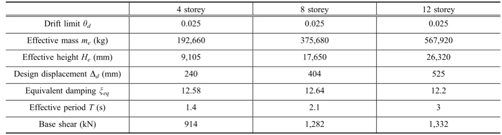
2.6.1 RC Frame Systems
The DDBD parameters calculated for the RC frame models are given in Table2.
2.6.2 RC Wall-Frame Systems
The DDBD parameters calculated for the RC wall-frame models are given in Table3.
2.6.3 RC Steel Braced Frame Systems
The DDBD parameters calculated for the steel braced RC frame models are given in Table4.
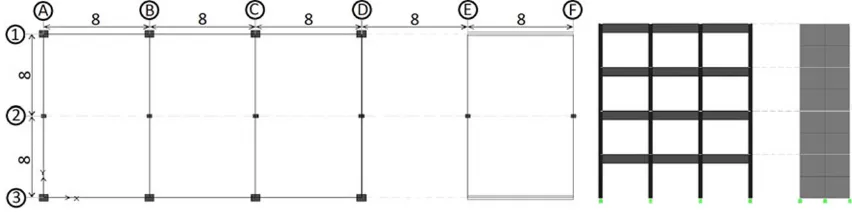
3. Structural Models
Three 4-story, 8-story and 12-story buildings with three different structural configurations (RC Frame, RC Wall-Frame and Steel Braced RC Wall-Frame Systems) are designed based on the DDBD approaches mentioned in each section and according to the following considerations.
The structures are assumed to be residential, placed in a very high seismicity region with Soil Type II and according to the Iranian Code of Practise for Seismic Design of Buildings (Standard No. 2800, third edition (2005)). The material properties are as the following:
fc0¼30 MPa; EC¼25740 MPa; fy¼400 MPa;
Es¼200000 MPa
An internal 2D frame is selected from each of the 4-story, 8-story and 12-story buildings. The frames are 3.5 m in height and have 3 spans with 5 m in width. Figures6,7and 8 display the schematic views of the above mentioned systems.
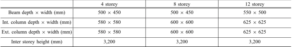
The cross section profiles that are designed for the mem-bers using DDBD approach are given in Tables5,6 and7.
4. Performance Verification
In order to evaluate seismic performance of the structures designed using this method, the nonlinear time-history analysis is carried out using PERFORM 3D (2006). For this purpose, FEMA concrete beam and FEMA concrete column have been used to model inelastic bending in concrete beams and columns, based on the FEMA 356 model. Brace Ele-ment is used for bracings and fiber eleEle-ments are used for simulation of shear walls. Each FEMA beam component is actually two components, namely a plastic hinge and an elastic segment (Fig.9).
The model for a FEMA concrete beam is similar to that for a steel beam. However, rotation hinges are used, instead of curvature hinges. This is because FEMA-356 gives the properties for concrete beams and columns in terms of plastic end rotations rather than as multiples of the yield rotation.
Most of the inelastic components in PERFORM-3D have the same form for the F–D relationship. This is a trilinear relationship with optional strength loss, as shown in Fig.10. For further description about the key points of the F–D relationship please refer to reference FEMA (2002). The widely used hysteretic models of Ramberg–Osgood (from
Blandon 2004) and Takeda (from Blandon 2004) were implemented for simulating the reinforcing steel and con-crete behavior, respectively (Figs.11,12).
Rayleigh damping is used in PERFORM-3D (2006) for time-history analysis of the structures.
Rayleigh damping assumes that the structure has a damping matrix,C, given by:
C¼aMþbK ð33Þ
whereMis the structure mass matrix,Kis the initial elastic stiffness matrix, anda andbare multiplying factors.
The physical meaning ofaM?bK damping is illustrated in Fig.13(PERFORM-3D2006).
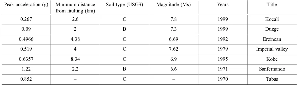
The models simulated using this software have been subjected to 7 accelerograms which were scaled to the uti-lized design spectrum. Table8 shows some of the most important specifications of the records, and the elastic acceleration response spectrum of these accelerograms is indicated in Fig.14.
Assignment of the base shear to the frames, walls and bracing elements of the analytical models are shown in Figs.15and16.
Calculating the design displacement profile is one of the most important steps of DDBD. Figures17,18and19 dis-play the displacement profiles of the 4, 8 and 12 story models for RC frame models, RC wall-frame and steel braced RC frame models, respectively.
In this section, a very important verification parameter, namely ‘‘inter-story drift’’ is discussed. Many studies have
shown that inter-story drift has a key role in damage potential of structures. Generally, building codes limit inter-story drift to values within the range of 2–2.5 % of the story height. As mentioned earlier, a value of 2.5 % was selected for this study. The inter-story drift response of the models are displayed in Figs.20, 21 and 22.
Fig. 5 DDBD flowchart for steel braced RC frames.
Table 2 DDBD parameters calculated for RC frame models.
4 storey 8 storey 12 storey
Drift limithd 0.025 0.025 0.025
Effective massme(kg) 192,660 375,680 567,920
Effective heightHe(mm) 9,105 17,650 26,320
Design displacementDd(mm) 240 404 525
Equivalent dampingneq 12.58 12.64 12.2
Effective periodT(s) 1.4 2.1 3
Table 3 DDBD parameters calculated for RC wall-frame models.
4 storey 8 storey 12 storey
Drift limithd 0.025 0.025 0.025
Effectivemassme(kg) 795,167 1,575,298 2,298,357
Effective heightHe(mm) 10,876 20,602 30,450
Design displacementDd(mm) 256 475 663
Equivalent dampingneq 12 11.25 10.14
Effective periodT(s) 1.79 2.76 3.50
Base shear (kN) 2,504 3,875 4,907
Table 4 DDBD parameters calculated for steel braced RC frame models.
4 storey 8 storey 12 storey
Drift limithd 0.025 0.025 0.025
Effective massme(kg) 229,836 462,550 694,873
Effective heightHe(mm) 9,670 18,390 27,140
Design displacementDd(mm) 230 414 587
Equivalent dampingneq 13.62 13.64 13.49
Effective periodT(s) 1.70 2.65 3.30
Base shear (kN) 650 992 1,299
Fig. 6 Plan and elevation of the RC frame models.
Fig. 8 Plan and elevation of the steel braced RC frame models.
Table 5 Final design results of RC steel braced frame models.
4 storey 8 storey 12 storey
Brace section 2UNP120 2UNP160 2UNP200
Beam depth9width (mm) 4009300 4509300 5009400
Int. column depth9width (mm) 4009400 5009500 5509550
Ext. column depth9width (mm) 4009400 4509450 5009500
Inter storey height (mm) 3,200 3,200 3,200
Table 6 Final design results of RC wall-frame models.
4 storey 8 storey 12 storey
Wall length (mm) 8,000 8,000 8,000
Wall thickness (mm) 200 300 350
Beam depth9width (mm) 6509400 7509450 7509450
Int. column depth9width (mm) 6509650 7509650 7509650
Ext. column depth9width (mm) 5509550 6509650 6509650
Inter storey height (mm) 3,200 3,200 3,200
Table 7 Final design results of RC frame models.
4 storey 8 storey 12 storey
Beam depth9width (mm) 5009450 5009450 5509500
Int. column depth9width (mm) 5809580 6009600 6259625
Ext. column depth9width (mm) 5809580 6009600 6259625
Figure20 represents the inter-story drift profiles of the RC frame models under the selected pulse-type records. In these figures, the design inter-story drift profile is also displayed. Referring to these diagrams, the method performs quite satisfactorily. Maximum inter-story drifts in all RC frame models fall under the specified design profile. The overall profile shapes are similar to those expected for rigid frames. The shape of the profiles for the tall RC frame model (12 story frame) are very similar to natural higher mode shapes of these structures derived from Eigen-value analysis of frames, implying that higher mode effects are important for tall frames.
Figure21 indicates inter-story drift profile of the RC wall-frame models. Displacement responses of the models are in close agreement with each other, and inter-story drifts of the all the models subjected to the records are below 2.5 %. All the lateral displacement responses exhibited some decrease in increasing displacement profile in upper stories which can be attributed to the fact that frames have dominant response in upper stories in com-parison with structural walls.
Fig. 9 Schematic view of FEMA beam element (PERFORM-3D2006).
Fig. 10 PERFORM action-deformation relationship (PER-FORM-3D2006).
Fig. 11 Ramberg–Osgood curve (from Blandon2004).
Fig. 12 Takeda model (from Blandon2004).
Figure22 indicates inter-story drift profile of the steel braced RC frame models. The inter-story drifts of the 4 and 8-story models subjected to the records are below 2.5 %, but inter-story drift of the 12-story model subjected to the records exceeded the design inter-story drift in Stories 1–4, which can be attributed to the bracing buckling in lower stories. The inter-story drifts of the 4
and 8-story models subjected to the records are below 2.5 %, except for Imperial Valley Record in both models and Erzincan and Sanfernando Record in the 8-story model. However, inter-story drift of the 12-story model subjected to the records exceeded the design inter-story drift in Stories 1–4 demonstrating the fact that this design method was not successful for the 12-story model.
Table 8 Characteristics of the selected records.
Peak acceleration (g) Minimum distance from faulting (km)
Soil type (USGS) Magnitude (Ms) Years Title
0.267 2.6 C 7.8 1999 Kocali
0.09 2 B 7.3 1999 Duzge
0.4966 4.38 C 6.69 1992 Erzincan
0.519 4 C 7.62 1979 Imperial valley
0.6357 8.34 C 6.9 1995 Kobe
1.22 2.2 B 6.6 1971 Sanfernando
0.852 – C – 1970 Tabas
5. Concluding Remarks
The present study focuses on seismic behavior of near-fault RC structures design with a new performance-based design tool called the DDBD.
For this purpose, seismic response of RC frame systems in addition to dual RC wall-frame and steel braced RC frame systems designed using DDBD are investigated.
Performance verification studies show that the method can be regarded as an appropriate alternative to current force-based seismic design of structures. The method, performed quite satisfactorily in term of maximum inter-story drift, even for tall models. Some deviations, especially in tall models, from design values are mainly due to the complex
and highly varying nature of frequency content of near-fault records. Another important finding of the study is that, the DDBD methodology is able to design structures with quite controlled residual behavior, an interesting subject which needs further studies.
Open Access
This article is distributed under the terms of the Creative Commons Attribution License which permits any use, distribution, and reproduction in any medium, provided the original author(s) and the source are credited.
Fig. 16 Profile of the story shear assignment to the frame and bracing.
Fig. 18 Displacement profile of RC wall-frame model.
Fig. 20 Inter-story drift profile of RC frame models.
References
Badoux, M., & Jirsa, J. O. (1990). Steel bracing of RC frames for seismic retrofitting. Journal of Structural Engineering, ASCE, 116(1), 55–74.
Belleri, A. (2009). Displacement based design for precast con-crete structures.PhD thesis, University of Toronto. Blandon, C. A. (2004). Equivalent Viscous Damping for
DDBD.MSc Thesis, ROSE School, Pavia, Italy.
Calvi, G. M., & Pavese, A. (1995). Displacement-based design of building structures. In A. S. Elnashai (Ed.), European seismic design practice: Research and application, pro-ceedings of the fifth SECED conference, Chester, United Kingdom, October 26–27 1995(pp. 127–132). Rotterdam, Netherlands: A.A. Balkema.
Calvi, G. M., & Kingsley, G. R. (1995). Displacement-based seismic design of multi-degree-of-freedom bridge struc-tures. Earthquake Engineering and Structural Dynamics, 24, 1247–1266.
CEN. (1998). Eurocode 8: Design provisions for earthquake resistance of structures, prEN-1998-1:200X, Revised Final PT Draft (preStage 49). Brussels, Belgium: Committee European de Normalization.
Chopra, A. K., & Goel, R. K. (2001). Direct displacement-based design: Use of inelastic vs. elastic design spectra. Earth-quake Spectra, EERI,17(1), 47–64.
Fajfar, P. (2000). A nonlinear analysis method for performance-based seismic design.Earthquake Spectra, 16(3), 573–592. Fardis, M. N., Panagiotakos, T. B., & Telemachos, B. (1997). Displacement-based design of RC buildings: Proposed
approach and application. In P. Fajfar & H. Krawinkler (Eds.),Proceedings of the seismic design methodologies for the next generation of codes. Bled, Slovenia, June 24–27 1997 (pp. 195–206). Rotterdam, Netherlands: A.A. Balkema.
FEMA 356. (2002). Prestandard and commentary for the seismic rehabilitation of buildings. Washington, D.C.: Federal Emergency Management Agency.
Freeman, S. A. (1998). The capacity spectrum method as a tool for seismic design. InProceedings of the 11th European Con-ference on Earthquake Engineering, Sept 6–11, Paris, France. Garcia, R., Sullivan, T. J., & Della Corte, G. (2010). Devel-opment of a displacement-based design for steel frame-RC wall buildings.Journal of Earthquake Engineering, 14(2), 252–277.
Ghaffarzadeh, H., & Maheri, M. R. (2006a). Cyclic tests on the internally braced RC frames. Journal of Seismology and Earthquake Engineering, 8(3), 177–186.
Ghaffarzadeh, H., & Maheri, M. R. (2006b). Mechanical com-pression release device in steel bracing system for retrofitting RC frames.Journal of Earthquake Engineering and Engi-neering Vibration, 5(1), 151–158. doi: 10.1007/s11803-006-0626-x.
Ghorbani-Asl, A. (2007). Performance-based seismic design of building structure. Doctor of Philosophy in Civil Engi-neering. Ottawa-Carleton Institute for Civil Engineering, Carleton University, Ottawa, Canada.
Gulkan, P., & Sozen, M. (1974). Inelastic response of reinforced concrete structures to earthquake motions. ACI Journal, 71(12), 604–610.
Higashi, Y., Endo, T., & Shimizu, Y. (1981). Experimental studies on retrofitting of reinforced concrete structural members. InProceedings of the Second Seminar on Repair and Retrofit of Structures (pp. 126–155). Ann Arbor, MI: National Science Foundation.
Iranian Code of Practice for Seismic Resistant Design of Buildings, Standard No. 2800, 3rd edition. (2005). Build-ing and HousBuild-ing Research Center, BHRC-PN S 253. Jacobsen, L. S. (1930). Steady forced vibration as influenced by
damping.Transactions of ASME, 52, 169–181.
Kowalsky, M. J., Priestley, M. J. N., & MacRae, G. A. (1995). Displacement-based design of RC bridge columns in seis-mic regions. Journal of Earthquake Engineering and Structural Dynamics, 24(12), 1623–1643.
Maheri, M. R., & Ghaffarzadeh, H. (2008). Connection over-strength in steel-braced RC frames.Journal of Engineering Structures, 30, 1938–1948.
Maheri, M. R., & Sahebi, A. (1997). Use of steel bracing in reinforced concrete frames.Engineering Structures, 19(12), 1018–1024.
Malekpour, S., Ghaffarzadeh, H., & Dashti, F. (2012). Direct displacement-based design of steel-braced reinforced con-crete frames. Journal of the Structural Design of Tall and Special Buildings. doi:10.1002/tal.1028.
Moehle, J. P. (1992). Displacement-based design of RC struc-tures subjected to earthquakes.Earthquake Spectra, EERI, 8(3), 403–428.
Pennucci, D., Calvi, G. M., & Sullivan, T. J. (2009). Dis-placement-based design of precast walls with additional dampers. Journal of Earthquake Engineering, 13(1), 40–65.
PERFORM-3D User Guide. (2006). Nonlinear analysis and performance assessment for 3D structures, VERSION 4, August 2006. Berkeley, CA: Computers and Structures, Inc.
Pettinga, J. D., & Priestley, M. J. N. (2005). Dynamic behaviour of reinforced concrete frames design with direct displace-ment-based design. Journal of Earthquake Engineering, 9(2), 309–330.
Priestley, M. J. N. (2003).Myths and fallacies in earthquake engineering, revisited, The Mallet Milne Lecture. Pavia, Italy: IUSS Press.
Priestley, M. J. N., & Grant, D. N. (2005). Viscous damping for analysis and design. Journal of Earthquake Engineering, 9(Special Issue 2), 229–255.
Priestley, M. J. N., & Kowalsky, M. J. (2000). Direct dis-placement-based design of concrete buildings. Bulletin of the New Zealand National Society for Earthquake Engi-neering, 33(4), 421–444.
Shibata, A., & Sozen, M. A. (1976). Substitute-structure method for seismic design in R/C.Journal of the Structural Divi-sion, 102(1), 1–18.
Sullivan, T. J., Priestley, M. J. N., & Calvi, G. M. (2005). Development of an innovative seismic design procedure for frame-wall structures.Journal of Earthquake Engineering, 9(Special Issue 2), 279–307.
Sullivan, T. J., Priestley, M. J. N., & Calvi, G. M. (2006). Direct displacement design of frame-wall structures. Journal of Earthquake Engineering, 10(Special Issue 1), 91–124. Sullivan, T. J., Priestley, M. J. N., & Calvi, G. M. (2004).
Displacement shapes of framewall structures for direct displacement based design. InProceedings of Japan–Eur-ope 5th Workshop on Implications of Recent Earthquakes on Seismic Risk, Bristol, UK.
Sullivan, T. J., Priestley, M. J. N., & Calvi, G. M. (2009). Introduction to a model code for displacement-based seis-mic design. In Proceedings, ACES Workshop on Perfor-mance-Based Earthquake Engineering. Corfu, Greece. Tasnimi, A. A., & Masoomi, A. (1999). Evaluation of response
of reinforced concrete frames strengthened with steel bracing. In Proceedings of the Third International Con-ference on Seismology and Earthquake Engineering, Iran, (in Farsi).
![Analyse acoustique de contrastes atypiques en anglais d’Irlande du Nord (Acoustic analysis of atypical contrasts in Northern Irish English) [in French]](data:image/gif;base64,R0lGODlhAQABAIAAAP///wAAACH5BAEAAAAALAAAAAABAAEAAAICRAEAOw==)