Performance Evaluation of Single Base Station
ToA-AoA Localization in an LTE Testbed
Alejandro Blanco
†⋆, Norbert Ludant
†, Pablo Jim´enez Mateo
†⋆, Zhenyu Shi
‡, Yi Wang
‡, Joerg Widmer
† †IMDEA Networks Institute, Madrid, Spain ⋆ Universidad Carlos III de Madrid, Madrid, Spain
‡ Huawei Technologies Co., Ltd, Shanghai, China
E-mails:†{firstname.lastname}@imdea.org
,
‡{firstname.lastname}@huawei.comAbstract—Precise localization is becoming an integral part of mobile network architectures, not only to provide location-based services but also to optimize the operation of the network itself through suitable context information. Location systems are of particular importance for indoor settings where GPS may be unavailable. While upcoming 5G systems will provide improved location accuracy, for a long time to come many areas will only have LTE coverage, and ubiquitous localization will thus also have to rely on LTE technology. To evaluate the location accuracy that can be achieved with current mobile systems, we implement a localization algorithm in a standard-compliant LTE testbed based on software-defined radios. We assess the localization accuracy in representative indoor scenarios. Despite a bandwidth of only 20MHz, the results show a good median error around 2m, but significantly larger errors may occur in non-line-of-sight cases. Nevertheless, the accuracy is sufficient for a range of potential applications.
I. INTRODUCTION
Location systems for cellular networks are rapidly gaining in importance, both due to the proliferation of location based services, as well as the promise of much more powerful mobile network management and control mechanisms that use location as context information. This is especially important in light of increasing device densities and wireless data rates. In fact, strict require-ments for localization have been already specified in the future 5G standard, requiring an accuracy of 1m or less in 99% of the cases for indoor and outdoor [1], [2]. However, the transition from Long Term Evolution (LTE) to 5G will be progressive. 5G rollout will begin in major urban areas as replacing most of the mobile infrastructure in one go is unaffordable for operators. This fact is reflected in the Cisco forecast and trend 2017-2022 [3] which predicts that the 5G devices and connection constitute over 3% of global mobile devices and connections by 2022. This leaves many areas and devices with only partial or even without 5G coverage. Ubiquitous location systems therefore have to incorpo-rate legacy mobile technology, most importantly LTE.
While the current localization techniques enabled by the LTE standard cannot achieve the high level of 5G location accuracy, they can provide a performance that
is sufficient for a range of important applications. Several techniques for localization are included in the 3GPP standard, such as fingerprinting or triangulation and tri-lateration approaches, based on Angle of Arrival (AoA), Time of Arrival (ToA) and reference signal received power. Such systems face many challenges: either the localization error reaches up to dozens of meters, they have high response times, or require coverage by several Evolved Node B (eNB), which, in particular indoors, is not always given. In addition, synchronization and/or clock errors are likely to degrade the accuracy due to the combination of several eNB measurements.
Hence, single eNB localization techniques using ToA and AoA measurements to estimate the direction and distance between the User Equipment (UE) and the eNB are highly important for next generation networks. Furthermore, such techniques will greatly benefit from upcoming technologies such as Massive Multiple Input Multiple Output (MIMO) systems [4], and from higher bandwidth allocation. Thus, evaluating and understand-ing the achievable accuracy and behavior of sunderstand-ingle eNB localization in current LTE networks is necessary to assess which location-based services can be supported. Moreover, it serves as an useful starting point for next generation localization techniques.
In this paper, we evaluate the achievable positioning accuracy for an LTE-compliant system. We consider a 2D space where the system exploits angular and distance information for the localization. The distance is extracted through ToA estimation using the LTE Sounding Ref-erence Signal (SRS), and the AoA is measured using the MUlti SIgnal Classification (MUSIC) algorithm. Our system is implemented on the eNB side to benefit from its improved RF hardware, antenna characteristics and computational power.
To do so, we carry out a measurement campaign in two different locations. The results of our performance evaluation indicate a median location error around 2m. While this performance does not meet the localization requirements of 5G and some Internet of Things (IoT) applications, such as robotics and augmented reality. But, it suffices for a great range of IoT applications which do not require a strict sub-meter accuracy, such as transportation and moving, sensing things, healthcare and many more [9], [10].
The rest of the paper is organized as follows. Section II reviews LTE characteristics and functionality related for the positioning system. In Section III, we describe the location system itself. Section IV provides the details of our measurement campaign and Section V presents the evaluation results. Finally, Section VI concludes the paper.
II. LTEBACKGROUND
This section gives an overview of the LTE concepts [11] that are related to localization: synchronization, ref-erence signals and how localization can be implemented within the LTE standard.
A. LTE Synchronization
Time and frequency synchronization between eNB and UE are critical to ensure reliable communication as well as precise positioning. The synchronization process includes two main steps:
• Timing symbol synchronization: It is the first timing
synchronization in LTE. The purpose is to set the boundaries between symbols.
• Timing subframe and frame synchronization: In
order to know exactly when to send the data, the UE needs to know the frame and subframe boundaries. The first step is done exploiting the redundancy in each symbol to estimate the boundary, given that the Cyclic PRE-fix (CP) is a copy of the end of the symbol added at the beginning of it.
The second step uses the Primary and Secondary Syn-chronization Signals (PSS and SSS). The UE estimates the cross-correlation of the PSS to synchronize every half frame since the PSS is sent two times per frame. Afterwards, the same process is applied to the SSS to achieve frame synchronization.
B. LTE Reference Signals
The reference signals are known sequences which are used for multiple purposes like channel estimation or equalization. The signals of interest for localization are:
• Sounding Reference Signal (SRS): The SRS is
transmitted in the uplink direction occupying up to 18MHz in its maximum configuration. It is used by the eNB to measure the uplink channel and the timing advance over a wider bandwidth. The signal is based on Zadoff-Chu sequences [12]. The main property of interest is the ideal cross-correlation: the cross-correlation of this sequence with a cyclic shifted version of itself is zero, except in the position of the lag.
• Positioning Reference Signal (PRS): The PRS is
transmitted in the downlink direction. Its main purpose is to measure the ToA at the UE side and, consequently, it can be used for positioning. Similar to the SRS, this signal occupies a wider bandwidth up to the maximum available.
While, in contrast to the PRS, the main purpose of the SRS is not to localize. It is very useful for this purpose since it occupies almost the whole bandwidth and therefore provides reasonably high time resolution. Besides, the Zadoff-Chu properties make the SRS more reliable in case of multi-path effects, thanks to the ideal cross-correlation property.
C. Localization in LTE
While LTE design naturally focuses on communi-cations first and foremost, it does support localization services through two main mechanisms [13]:
• Observed time difference of arrival: Using a similar
concept as GPS, the UE measures the downlink signals from several synchronized eNBs, and the localization is done measuring the time difference of arrival among them. Starting with Release 9, the PRS was included to enhance the accuracy of this mechanism. Furthermore, the same concept for the uplink direction was added in Release 11, where several eNBs measure the same signal sent by the UE.
• Enhanced cell ID: Measurements like timing
ad-vance, angle of arrival and reference signal received power, together with the ID of the serving cell are used to improve the estimation of the position of the UE.
III. LOCALIZATIONPROCESSDESCRIPTION
For this reason, we consider a 2D location system based on LTE, where the UE is synchronized by the eNB over the air. The eNB has to measure two variables to determine the UE location, the first is the AoA, giving the direction at which the UE is located, and the second is the ToA, which provides an estimate of the distance between both.
A. AoA Estimation
There are several algorithms to estimate the AoA of an incoming signal, but none are included in the LTE standard. For our system, we have selected MU-SIC algorithm [14]. It is a classic algorithm for AoA estimation which is gaining relevance thanks to MIMO [15]. MUSIC is based on decomposing through an eigendecomposition the correlation matrix of the signal into two subspaces: the signal and the noise. The signal subspace contains the information regarding the AoA of the incoming signal. To extract the AoA, instead of using the signal subspace, MUSIC exploits the eigenvector property of orthogonality to multiply a set of steering vectors, each one associated with a possible AoA, by the noise subspace. The AoA related to steering vector which is orthogonal to the noise subspace is the AoA of the incoming signal.
Consider an Uniform Linear Array (ULA) of antennas where the number of antennas is K and the distance between antennas is d. Due to multipath effects, there areP signals which arrive at the ULA. Each signal has an associated AoA,αp wherep∈ {0,1,· · ·, P−1}. The
ULA output is defined as:
x(t) = PX−1
p=0
ap(αp)sp(t) +w(t), (1)
wheresp(t)is the signal source,apis the steering vector
associated tosp andw(t)is a vector of white Gaussian
noise. The steering vector is given by:
a(αp) = [1, e−j2πdλ sin(αp),· · ·, e−j2πd(λK−1)sin(αp)] (2)
We can write the correlation matrix of the input stream as follows:
Rx(t) =E{x(t)xH(t)}=ASAH+σ2I, (3)
whereSis the signal covariance matrix, the symbol(·)H
represents the hermitian operator,σ2is the noise power,
Iis the identity matrix and A is the steering matrix.S
is assumed to be definite positive (rankP), which gives the following representation:
R=UΛUH (4)
whereU is an unitary matrix which contains the eigen-vectors and Λ is a diagonal matrix which contains K
positive and real eigenvalues.
MUSIC splits the eigenvalue/vector pairs into two subspaces, the signal and noise. The signal eigenvectors
are P eigenvectors where each one has an associated eigenvalue larger than the noise power such that (λ0,· · ·, λP−1 > σ), whereas the remaining ones are equal to
the noise power (λP =· · ·=λK−1 =σ). This results
in the following representation:
R=UsΛsUHs +UnΛnUHn (5)
where the columns of the signal subspace matrix, Us, are the P principal eigenvectors and Un contains the remainingK−P eigenvectors.
The orthogonality property of the eigenvectors ensures that Un is orthogonal to Us and, consequently, to the steering matrix. Therefore, MUSIC exploits this fact to extract the AoA. To do so, MUSIC defines the spatial spectrum as:
pM(σ) = 1
kaH(σ)Unk 0≤σ≤π (6)
In a scenario where the main path is the Line-Of-Sight (LOS), the associated AoA is the angle which maximizes the MUSIC spatial spectrum:
AoA= arg max
σ (pM(
σ)) (7)
B. ToA estimation
Since the UE is synchronized with the eNB, the ToA can simply be measured by cross-correlation between the SRS sent by the UE and the received one by the eNB. The argument of the maximum value of the cross-correlation indicates the communication lag. In fact, this lag does not represent the propagation delay introduced by the channel, it represents twice that value because the same delay is added in the synchronization process of the UE. That is, the UE time reference, which is used to determine the start of the transmission of a frame, is the one of the eNB plus the propagation delay of the channel, since the synchronization is done over the air. LTE defines the concept of timing advance to compensate for it and avoid that the UE sends the information outside the slots given by the eNB. eNB measures the timing advance in the same way as the ToA, by the cross-correlation of the random access preamble or with the SRS, and sends it to the UE. The timing advance resolution, as is defined in LTE, corresponds to a distance of 78.12m. In case the UE is closer to the eNB than this resolution (which is the case in our experiments), the timing advance is 0 and does not have any effect.
The SRS received by the eNB in the frequency domain is:
Y[k] =H[k]X[k] +W[k], (8)
where H[k], X[k] andW[k] represent the kth sample
We denote the observed cross-correlation between the received and sent SRS asrSRS[n], given by:
rSRS[n] =IDF T{Y[K]X∗[K]}, (9)
where n is the discrete time sample, the symbol (·)∗
denotes the conjugate operator and IDF T{·} denotes the Inverse Discrete Fourier Transform.
The eNB can estimate the lag by finding the argu-ment which maximizes the absolute value of the cross-correlation:
ˆi= arg max n |rSRS[
n]| (10)
This argument corresponds to a given sample and be-cause the SRS is a time discrete sequence, this sample corresponds to a given moment in the discrete time. Let us define the moment when the UE sends the SRS as
t0 +δ, where δ is the propagation delay introduced
by the channel. In addition, tˆi is the moment that the
cross-correlation peaks at the eNB, which corresponds tot0+ 2δ. Consequently, we can express the ToA as:
δ=tˆi−t0
2 (11)
Finally, we can express the distance given by the ToA
dT oAas:
dT oA=cδ, (12)
wherecis the speed of light in the space. Note that the
dT oAvalues are also discrete and its resolution directly depends on the bandwidth of the SRS.
IV. IMPLEMENTATION
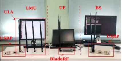
Our setup consists of one eNB and one UE. The UE side runs on a laptop with 16GB of RAM and 4 cores at 2.8GHz and we use an inexpensive bladeRF Software-Defined Radio (SDR) for the radio communications. The eNB is a desktop PC with 16 GB RAM and 8 cores at 3.4 GHz. We also run the Evolved Packet Core (EPC) in a virtual machine on the same desktop PC, with 1 core and 6GB RAM. The eNB is connected to an Universal Software Radio Peripheral (USRP) X310, a type of SDR, which serves as radio interface. We measure AoA using an additional Location Measurement Unit (LMU) composed of a USRP X310 equipped with two TwinRX daughterboards to ensure phase synchronization among the four available channels. The four antennas are LTE compliant with a gain of 7dBi and arranged as an uniform linear array. This LMU is driven by another PC with the same characteristic as the eNB one. The complete setup is depicted in Fig. 1.
The software for the LTE functionality (eNB, UE and EPC) is based on srsLTE [16]. srsLTE is a fully operational open source software implementation of the LTE cellular systems. We chose this setup since it performed better and was more stable than the other most commonly used LTE software implementation,
Fig. 1: LTE location system components
OpenAirInterface [17]. The LMU is based on GNU Radio [18], an open source software which provides signal processing blocks for SDRs. Out of the box, srsLTE does not fully support the SRS on the eNB side, whereas the UE can correctly send it. We thus modify the srsLTE eNB implementation to set the SRS configuration in the Radio Resource Control (RRC) messages as determined by the standard, specifically, the system information block 2 and RRC connection setup. Regarding the LTE configuration, the system uses the maximum available bandwidth of 20 MHz in frequency division duplexing mode with a normal CP. The center frequency is 1.8GHz. We configure the SRS to be sent every 50 ms with a bandwidth of 18MHz, the maximum that LTE supports. This gives a ToA resolution of 8.625m.
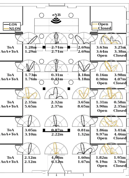
We run our measurements in two indoor locations at IMDEA Networks. The first one is an empty room without furniture with a size of 21x9m where perfect coverage and visibility are available over the whole scenario. In contrast, the second scenario is a 19x15m office space, where the furniture and dividing walls create Non-Line-Of-Sight (NLOS) areas and increase the number of multipath components. Fig. 3 shows the floor plan of the office (as well as the measurement results). It has a central open area with desks, chairs and screens, and individual offices on the right and left hand side of it. The obstacles that create NLOS areas are the pillars and the dividing wall indicated in thick black, as well as the glass walls which separate the offices from the open area. For the rest of the paper, we will refer to the first scenario as the auditorium and the second one as the office.
There are 40 and 25 measurement points in the auditorium and office scenarios, respectively. For 5 of the points in the office scenario that are located inside closed offices, we took measurements twice, once with the office door open and once with it closed. We carry out experiments in each point measuring the AoA and ToA to determine the overall localization accuracy.
V. NUMERICALRESULTS
0 5 10 15 20 25 30 35 40 45 0
0.2 0.4 0.6 0.8 1
Auditorium LOS Office NLOS Office
(a) CDF of the AoA error
0 1 2 3 4 5
0 0.2 0.4 0.6 0.8 1
Auditorium LOS Office NLOS Office
(b) CDF of the ToA error
0 2 4 6 8 10
0 0.2 0.4 0.6 0.8 1
Auditorium LOS Office NLOS Office
(c) CDF of the localization error
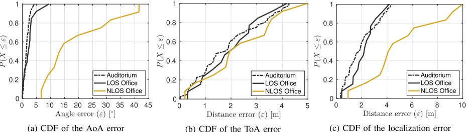
Fig. 2: AoA, ToA and localization error evaluation
first discussed separately, and then the performance of joint estimation for localization is presented. We note that the localization accuracy is degraded in case of NLOS. For this reason, we separately show the cases of LOS and NLOS in the office scenario. Finally, we provide a visual representation of the measurements in the office scenario to assess the performance in detail.
A. AoA
Fig. 2a shows the Cumulative Distribution Function (CDF) of the AoA error. For the case of LOS, the errors in the auditorium and the offices are very similar, in contrast to the case of NLOS. The fiftieth percentile of the cases have an AoA error below 1.4◦and 2.2◦in the
auditorium and LOS office, whereas in the NLOS office case, they are below 13.4◦. The effects of NLOS are
ex-tremely noticeable in the office and degrade considerably the AoA performance. Also, the maximum error in LOS office is considerably larger compared to the auditorium due to the richer multipath environment. Moreover, the highest errors in the auditorium and LOS office case do not come from the furthest points. Thus, this indicates that they are caused by multipath instead of the distance.
B. ToA
As explained in Section III-B, the measured ToA depends on the symbols of the SRS and is measured with the granularity of a symbol length. In addition, for each measurement point, we see a certain variability in the ToA discrete values. Such variations can be caused by systematic delays because of several factors, such as hardware processes of the internal FPGA of the SDRs, software process executed on the PC and minor synchronization errors of the system. While this effect degrades the performance relying on individual ToA measurements, the system can achieve higher accuracy when averaging over the set of measurements due to these fluctuations. In other words, as these fluctuations produce that the ToA varies between two or more discrete values, the system estimates one depending on the underlying ToA. Hence, averaging over the set of
measurements results in an more accurate ToA. At the same time, this mitigates the synchronization errors.
The ToA results are illustrated in Fig. 2b. They behave very similar for all scenarios. First, it indicates that the lack of LOS does not significantly degrade the accuracy. Second, the office environment has more multipath com-ponents compared to auditorium, but the performance in both is very similar, indicating that the multipath does not significantly deteriorate performance. The median distance error is below or equal to 1.76, 2.05 and 1.92m for auditorium, LOS and NLOS office. Although, the ToA resolution of an individual ToA measurement is 8.625m, the variability in the measurements plays a key role to improve the performance when averaging measurements over time.
C. Localization
Fig. 2c shows the CDF for the localization error. The localization performance mainly depends on the AoA accuracy in the NLOS cases and not on the ToA. The results for auditorium and LOS office show a similar behavior with a median error of 1.76 and 2.12m, re-spectively, whereas in the NLOS office it is 4.67m. In extreme cases, the location can have an error of up to 9.97m in NLOS due to very low AoA accuracy. However, the remaining scenarios have a maximum error of 4.3 and 4.48m.
D. Further observations
Fig. 3 shows the floor plan of the office scenario where we illustrate the MUSIC spatial spectrum for each measurement point. The text boxes below these profiles represent the error values in meters of the ToA (top) and the overall localization with AoA and ToA (bottom). The black and yellow color of the MUSIC spatial spectrum represents whether a point is LOS or NLOS. In addition, for the cases within the offices, the dashed line represents measurements taken with the door open and the solid one with the door closed.
come from a reflection instead of the direct path. Note also that for the case behind the wall, where there are no strong reflections, the AoA is slightly shifted from 90◦
to 80◦. In the two furthest points from the eNB within
the offices, the AoAs come from the door, whereas with the door closed, the AoAs come from the direct path. For the remaining points, the performance of the AoA behaves similar for both cases.
Fig. 3: Measurement errors of ToA and overall local-ization (AoA+ToA) in the office. Each point contains the MUSIC spatial spectrum as well as the error values for ToA and localization. Besides, on the right side two MUSIC spectrum and two error values appear to consider whether the door is closed or open
VI. CONCLUSION
While 5G network standards come with very strict lo-calization requirements and improved lolo-calization mech-anisms, LTE networks will continue to be used along with 5G for quite some time to come. This implies that ubiquitous location-based services will also have to make use of LTE localization schemes whenever 5G is not available. Evaluating the potential of the current LTE standard for localization is thus important to understand overall performance of localization in future mobile systems. We have tested the performance of a single eNB localization system in an LTE testbed based on software-defined radios. The measurements show that in LOS conditions the system has a median localization error
around 2m. However, localization accuracy is degraded in cases of NLOS with a median error of 4.67m. Finally, we observe that an LTE location system can achieve an accuracy that covers a wide range of location-based service requirements, even including some of the future IoT scenarios.
REFERENCES
[1] 3GPP TR 38.913 v14.3.0 ”5G;Study on Scenarios and Require-ments for Next Generation Access Technologies”.
[2] 3GPP TR 22.872 V2.0.0 Technical Specification Group Services and System Aspects, ”Study on positioning use cases”, May 2018.
[3] V. Cisco, “Cisco visual networking index: Forecast and trends, 2017–2022,”White Paper, 2018.
[4] L. Lu, G. Y. Li, A. L. Swindlehurst, A. Ashikhmin, and R. Zhang, “An overview of massive mimo: Benefits and challenges,”IEEE journal of selected topics in signal processing, vol. 8, no. 5, pp. 742–758, 2014.
[5] J. A. del Peral-Rosado, J. A. L´opez-Salcedo, G. Seco-Granados, F. Zanier, and M. Crisci, “Achievable localization accuracy of the positioning reference signal of 3gpp lte,” in2012 International Conference on Localization and GNSS, June 2012, pp. 1–6. [6] W. Xu, M. Huang, C. Zhu, and A. Dammann, “Maximum
like-lihood toa and otdoa estimation with first arriving path detection for 3gpp lte system,”Transactions on Emerging Telecommunica-tions Technologies, vol. 27, no. 3, pp. 339–356, 2016. [7] J. A. del Peral-Rosado, J. A. Lopez-Salcedo, G. Seco-Granados,
F. Zaniera, P. Crosta, R. Ioannides, and M. Crisci, “Software-defined radio lte positioning receiver towards future hybrid localization systems,” in 31st AIAA International tions Satellite Systems Conference, International Communica-tions Satellite Systems Conferences (ICSSC), 2017, pp. 337–340. [8] Q. Liu, R. Hu, and S. Liu, “A wireless location system in lte
networks,”Mobile Information Systems, vol. 2017, 2017. [9] S. M. Razavi, F. Gunnarsson, H. Ryd´en, ˚A. Busin, X. Lin,
X. Zhang, S. Dwivedi, I. Siomina, and R. Shreevastav, “Posi-tioning in cellular networks: Past, present, future,” in2018 IEEE Wireless Communications and Networking Conference (WCNC). IEEE, 2018, pp. 1–6.
[10] D. Stojanovi´c and N. Stojanovi´c, “Indoor localization and track-ing: Methods, technologies and research challenges,”Facta Uni-versitatis, Series: Automatic Control and Robotics, vol. 13, no. 1, pp. 57–72, 2014.
[11] LTE; Evolved Universal Terrestrial Radio Access (E-UTRA); Physical channels and modulation.
[12] M. Gul, X. Ma, and S. Lee, “Timing and frequency syn-chronization for ofdm downlink transmissions using zadoff-chu sequences,” IEEE Transactions on Wireless Communications, vol. 14, no. 3, pp. 1716–1729, 2015.
[13] J. A. del Peral-Rosado, R. Raulefs, J. A. L´opez-Salcedo, and G. Seco-Granados, “Survey of cellular mobile radio localization methods: from 1g to 5g,” IEEE Communications Surveys & Tutorials, vol. 20, no. 2, pp. 1124–1148, 2017.
[14] H. Krim, M. Viberget al., “Sensor array signal processing: two decades later,” 1995.
[15] X. Zhang, L. Xu, L. Xu, and D. Xu, “Direction of departure (dod) and direction of arrival (doa) estimation in mimo radar with reduced-dimension music,” IEEE communications letters, vol. 14, no. 12, pp. 1161–1163, 2010.
[16] I. Gomez-Miguelez, A. Garcia-Saavedra, P. D. Sutton, P. Serrano, C. Cano, and D. J. Leith, “srsLTE: An open-source platform for lte evolution and experimentation,” inProc. of ACM WiNTECH, 2016, pp. 25–32.
[17] H. Anouar, C. Bonnet, D. Cˆamara, F. Filali, and R. Knopp, “An overview of OpenAirInterface wireless network emulation methodology,”ACM SIGMETRICS Perform. Eval. Rev., vol. 36, no. 2, pp. 90–94, 2008.