UNIVERSIDAD CARLOS III DE MADRID
TESIS DOCTORAL
ENHANCING
W
IRELESSLOCAL
AREA
NETWORKS BY
LEVERAGING
DIVERSE
FREQUENCY
RESOURCES
Autor: Thomas Nitsche
Director: Dr. Joerg Widmer, IMDEA Networks Institute
DEPARTAMENTO DE INGENIER´IA TELEM ´ATICA
UNIVERSIDAD CARLOS III DE MADRID
Ph.D. Thesis
ENHANCING
W
IRELESSLOCAL
AREA
NETWORKS BY
LEVERAGING
DIVERSE
FREQUENCY
RESOURCES
Author: Thomas Nitsche
Director: Dr. Joerg Widmer, IMDEA Networks Institute
DEPARTMENT OF TELEMATIC ENGINEERING
Enhancing Wireless Local Area Networks by Leveraging Diverse Frequency Resources
A dissertation submitted in partial fulfillment of the requirements for the degree of Doctor of
Philosophy
Prepared by Thomas Nitsche
Under the advice of
Dr. Joerg Widmer, IMDEA Networks Institute
Departamento de Ingenier´ıa Telem´atica, Universidad Carlos III de Madrid
Date: July, 2015
Contact: thomas.nitsche@imdea.org
TESIS DOCTORAL
ENHANCINGWIRELESSLOCALAREA NETWORKS BYLEVERAGINGDIVERSE FREQUENCY RESOURCES
Autor: Thomas Nitsche
Director: Dr. Joerg Widmer, IMDEA Networks Institute
Firma del tribunal calificador:
Presidente:
Vocal:
Secretario:
Calificaci´on:
Acknowledgements
I would like to express my sincere thanks to all those who made this thesis possible and
provided help and support. First of all to my supervisor Dr. J¨org Widmer for his guidance and profound advice on writing this thesis as well as his academic mentoring. Further, thanks are
owed to Dr. Thomas Fuhrmann and Dr. Edward Knightly, who took their share in guiding my
academic work. My sincere gratitude also goes to my thesis committee: Dr. Albert Banchs, Dr. Kyle Jamieson and Dr. Ralf Steinmetz for insightful comments as well as supporting my research.
Along the same lines, I would like to thank all those people that I met along the way at
Technische Universit¨at M¨unchen, IMDEA Networks Institute and Rice University for discussion, advice and encouragements: Michael Weiss, Dr. Bj¨orn Saballus, Dr. Johanna Amann, Allyson
Sim, Arash Asadi, Ignacio de Castro Arribas, Qing Wang, Dr. Jose Felix Kukielka, Dr. Adrian
Loch, Dr. Mathias Hollick, Dr. Alexander K¨uhne, Jie Xiong, Jon Gjengset, Pablo Salvador, Maria Isabel Sanchez, Adriana Flores Middelton, Dr. Narendra Anand, Dr. Oscar Bejarano, Ryan E.
Guerra, Sadia Quadri, Dr. Carlos Cordeiro, Dr. Eldad Perahia, Irene Tejado and Guillermo Bielsa.
Special thanks belong to Dr. Benedikt Elser and Dr. Georg Acher for their ’unofficial’ academic mentoring.
Finally, I want to express my profound gratitude to my beloved parents, my family and to
Daniela for their love and continuous support.
Abstract
In this thesis, signal propagation variations, that are experience over the frequency resources
of IEEE 802.11 Wireless Local Area Networks (WLANs) are studied. It is found that exploitation of these variations can improve several aspects of wireless communication systems. To this aim,
frequency varying behavior is addressed at two different levels.
First, the intra-channel scale is considered, i.e. variations over the continuous frequency block that a device uses for a cohesive transmission. Variations at this level are well known but
cur-rent wireless systems restrict to basic equalization techniques to balance the received signal. In
contrast, this work shows that more fine grained adaptation to these differences can accomplish throughput and connection range gains.
Second, multi-frequency band enabled devices that access widely differing frequency
re-sources in the millimeter wave range as well as in the microwave range are analyzed. These devices that are expected to follow the IEEE 802.11ad specification experience intense
propaga-tion variapropaga-tions over their frequency resources. Thus, a part of this thesis revises, the theoretical
specification of the IEEE 802.11ad standard and complements it by a measurement study of first generation millimeter wave devices. This study reveals deficiencies of first generation
millime-ter wave systems, whose improvement will pose new challenges to the protocol design of future
generation systems. These challenges are than addressed by novel methods that leverage from frequency varying propagation characteristics.
The first method, improves the beam training process of millimeter wave networks, that need highly directional, though electronically steered, transmissions to overcome increased free space
attenuation. By leveraging from omni-directional signal propagation at the microwave bands,
efficient direction interference is utilized to provide information to millimeter wave interfaces and replace brute force direction testing. Second, deafness effects at the millimeter wave band,
which impact IEEE 802.11 channel access methods are addressed. As directional communication
on these bands complicates sensing the medium to be busy or idle, inefficiencies and unfairness are implied. By using coordination message exchange on the legacy Wi-Fi frequencies with
omni-directional communication properties, these effects are countered. The millimeter wave bands can
thus unfold their full potential, being exclusively used for high speed data frame transmission.
Table of Contents
Acknowledgements ix
Abstract xi
Table of Contents xiii
List of Tables xvii
List of Figures xxi
List of Acronyms xxiii
Introduction 1
Motivation . . . 2
Scope . . . 4
Contributions . . . 5
I Adapting IEEE 802.11 to Intra-Channel Propagation Variations 9 1 Background on IEEE 802.11 Communication 13 1.1 Radio Wave Propagation . . . 13
1.1.1 Free Space . . . 14
1.1.2 Atmospheric Absorption . . . 14
1.1.3 Multipath Propagation . . . 15
1.2 IEEE 802.11 . . . 19
1.2.1 Standardization History . . . 19
1.2.2 Channelization and Frequency Bands . . . 20
1.2.3 Network Structures . . . 22
1.3 MAC-Layer . . . 22
1.3.1 Medium Access Techniques . . . 23
1.3.2 Hidden Node Problem . . . 25
1.3.3 Frame Aggregation . . . 27
1.4 PHY-Layer . . . 27
1.4.1 Frame Format . . . 28
1.4.2 Modulation . . . 29
1.4.3 MIMO . . . 32
2 OFDM Sub-Carrier Switch Off 35 2.1 Mechanism . . . 36
2.1.1 Adaptive Sub-Carrier Switch Off . . . 38
2.1.2 Threshold-Based Adaptive Sub-Carrier Switch Off . . . 38
2.2 Hardware Platform and Experimental Setup . . . 39
2.2.1 PHY-Layer Structure . . . 40
2.2.2 WARPnet Measurement Setup . . . 41
2.2.3 Measured Values . . . 42
2.2.4 General Measurement Setup . . . 43
2.2.5 Feedback Mechanism . . . 44
2.3 Results . . . 44
2.3.1 Throughput Gain for SSO . . . 44
2.3.2 Parameter Configuration for SSO . . . 46
2.3.3 Adaptive Sub-Carrier Switch Off . . . 48
2.4 Related Work . . . 49
2.5 Conclusion . . . 50
II Leveraging from Varying Multi-Frequency Band Propagation 53 3 Background on Multi-band WiFi 57 3.1 IEEE 802.11ad . . . 58
3.1.1 Directional Communication . . . 59
3.1.2 IEEE 802.11ad Device Classes and Use Cases . . . 60
3.1.3 Design Assumptions . . . 60
3.1.4 Physical Layer . . . 62
3.1.5 Network Architecture . . . 63
3.1.6 IEEE 802.11ad Medium Access Control Layer . . . 66
3.1.7 Beamforming Concept . . . 69
3.1.8 Beamforming Protocol . . . 72
3.2 Performance Analysis of Millimeter Wave Networks . . . 75
3.2.1 Measurement Setup . . . 76
3.2.2 Results . . . 81
3.2.3 Discussion . . . 92
TABLE OF CONTENTS xv
4 Multi-Frequency Band Beam Steering 97
4.1 System Architecture . . . 99
4.1.1 IEEE 802.11ad and mm-Wave Wi-Fi . . . 99
4.1.2 Node and System Architecture . . . 100
4.2 Mechanism . . . 102
4.2.1 Out-of-Band Sector Inference and Profile History . . . 103
4.2.2 Profile History Aggregation . . . 103
4.2.3 Line-Of Sight Inference and Reflected Path Rejection . . . 104
4.2.4 Sector Mapping . . . 104
4.2.5 Optional Sector Refinement . . . 105
4.3 Implementation and Evaluation . . . 106
4.3.1 Blind Beam Steering (BBS ) Prototype . . . 106
4.3.2 Direct Path Detection Accuracy . . . 107
4.3.3 Robustness to Multipath and Signal Blockage . . . 108
4.3.4 Training Overhead . . . 110
4.3.5 Time of Directional Link Establishment . . . 111
4.3.6 Direct Path Detection under Mobility . . . 112
4.4 Related Work . . . 112
4.5 Conclusion . . . 113
5 Multi-Frequency Band MAC Enhancements for Fairness and Efficiency 115 5.1 Fairness Impairments in Directional CSMA/CA . . . 117
5.1.1 IEEE 802.11ad CSMA/CA . . . 118
5.1.2 Centralized CSMA/CA . . . 119
5.2 Dual-Band CSMA/CA . . . 119
5.2.1 Dual-Band CSMA/CA Protocol . . . 120
5.2.2 Fairness and Throughput . . . 121
5.3 Simulation Models . . . 121
5.4 Results . . . 122
5.4.1 Homogeneous Scenario . . . 123
5.4.2 Heterogeneous scenario. . . 128
5.5 Related Work . . . 128
5.6 Conclusion . . . 129
Summary and Future Work 130
List of Tables
2.1 WARP: Sub-carrier assignment. . . 40
2.2 WARP: Modulation base rates. . . 42
2.3 WARP: Throughput reduction due to FEC. . . 42
3.1 IEEE 802.11ad: Typical device configurations. . . 61
3.2 D5000 and WiHD frame periodicity. . . 82
4.1 BBS and IEEE 802.11ad time comparison for directional link establishment. . . . 111
5.1 Dual-Band CSMA/CA: Parameters in 60 GHz and 5 GHz frequency bands. . . . 123
List of Figures
1.1 Free space attenuation . . . 15
1.2 Attenuation due to atmospheric absorption. . . 15
1.3 Electro magnetic wave reflection. . . 16
1.4 Elector magnetic wave scattering. . . 17
1.5 Elector magnetic wave diffraction. . . 18
1.6 Channel state example. . . 18
1.7 IEEE 802.11 DCF operation. . . 24
1.8 Hidden node problem. . . 25
1.9 PCF beacon interval structure. . . 26
1.10 IEEE 802.11 frame structure. . . 29
1.11 DSSS signal characteristics. . . 30
1.12 IEEE 802.11 MIMO frame structure. . . 33
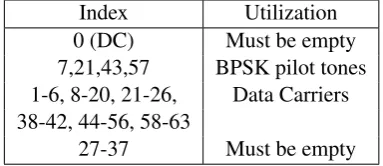
2.1 Sub-carrier allocation of the WARP OFDM PHY-layer. . . 40
2.2 WARP OFDM PHY-layer frame format. . . 41
2.3 SSO experimental setup. . . 42
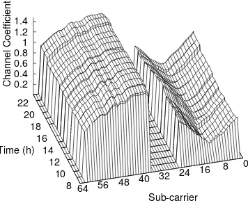
2.4 SSO throughput evaluation: Channel coefficients. . . 45
2.5 SSO throughput evaluation: QPSK throughput. . . 45
2.6 SSO throughput evaluation: 16-QAM throughput. . . 45
2.7 SSO throughput gain. . . 46
2.8 SSO threshold determination: Channel coefficients. . . 47
2.9 SSO threshold determination: Throughput comparision. . . 47
2.10 Adaptive SSO evaluation: Throughput comparision. . . 48
2.11 Adaptive SSO evaluation: Channel coefficients. . . 49
2.12 Adaptive SSO evaluation: Throughput. . . 49
3.1 Virtual antenna sectors. . . 59
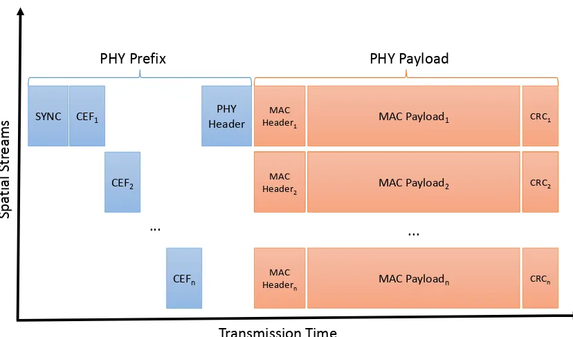
3.2 IEEE 802.11ad packet structure. . . 63
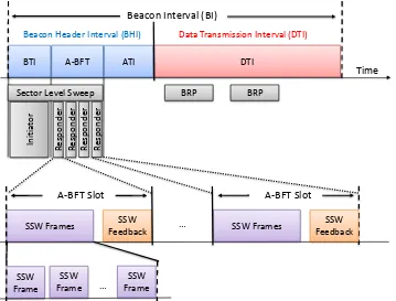
3.3 IEEE 802.11ad beacon interval structure. . . 64
3.4 Dynamic channel allocation example. . . 68
3.5 Sector level sweep structure. . . 70
3.6 Transmit and receive sector training. . . 70
3.7 Beam refinement transactions. . . 72
3.8 Association beamforming training. . . 73
3.9 Beam pattern analysis setup. . . 78
3.10 Dell D5000 device discovery frame. . . 78
3.11 Reflection analysis setup. . . 79
3.12 Interference analysis setup. . . 80
3.13 Reflected interference: Measurement setup. . . 81
3.14 Dell D5000 frame flow. . . 82
3.15 WiGig data frame length. . . 83
3.16 Percentage of long frames in WiGig. . . 83
3.17 WiGig medium usage. . . 83
3.18 MCS with low traffic. . . 84
3.19 Dell D5000 frame amplitudes and rate. . . 85
3.20 DVDO Air-3c WiHD frame flow. . . 85
3.21 Quasi omni-directional beam patterns swept by the Dell D5000. . . 86
3.22 Direction beam pattern measurement results. . . 87
3.23 Reflections for Dell D5000. . . 88
3.24 Reflections for DVDO Air-3c WiHD. . . 88
3.25 Inter system interference effects. . . 89
3.26 Side lobe interference impact. . . 91
3.27 Reflection interference impact. . . 92
4.1 Blind Beam Steering (BBS )system architecture. . . 101
4.2 Angular profile: Unobstructed direct path. . . 105
4.3 Angular profile: Multipath and blockage. . . 105
4.4 BBS measurement floor plan. . . 107
4.5 BBS prototype platform. . . 107
4.6 BBS: Detection accuracy results. . . 108
4.7 BBS: Peak to average ratio in relation to accuracy. . . 109
4.8 BBS: Blockage impact . . . 109
4.9 BBS: Overhead Results . . . 110
5.1 RTS collision due directional transmit focus on Access Point (AP). . . 116
5.2 Missed RTS due to receive sector misalignment. . . 116
5.3 Excessive backoff behavior of CSMA/CA in IEEE802.11ad . . . 118
5.4 Excessive deferral with colliding RTS messages in CSMA/CA with broadcast CTS 118 5.5 Channel access mechanism of the dual-band approach. . . 121
5.6 Interference in a directional transmission network. . . 122
LIST OF FIGURES xxi
5.8 Dual-Band CSMA/CA: Throughput results. . . 124
5.9 Dual-Band CSMA/CA: Channel time distribution. . . 125
5.10 Dual-Band CSMA/CA: Short term fairness. . . 126
5.11 Dual-Band CSMA/CA: Long term fairness. . . 126
5.12 Dual-Band CSMA/CA: Maximum frame transmission delay (4 nodes). . . 126
5.13 Dual-Band CSMA/CA: Maximum frame transmission delay (16 nodes). . . 126
5.14 Dual-Band CSMA/CA: Frame size impact. . . 128
Acronyms
A-BFTAssociation Beamforming Training.
APAccess Point.
ATIAnnouncement Transmission Interval.
BBS Blind Beam Steering.
BERBit Error Rate.
BFBeam Forming.
BHIBeacon Header Interval.
BIBeacon Interval.
BPSKBinary Phase Shift Keying.
BRPBeam Refinement Protocol.
BSSBasic Service Set.
CBAPContention Based Access Period.
CCKComplementary Code Keying.
CDFCumulative Distribution Function.
CDMACode Division Multiple Access.
CFPContention Free Period.
CPContention Period.
CRCCyclic Redundancy Check.
CSMA/CACarrier Sense Multiple Access with
Collision Avoidance.
CTSClear To Send.
CWContention Window.
DCFDistributed Coordination Function.
DIFSDCF Inter Frame Spacing.
DMGDirectional Multi-Gigabit.
DSSSDirect Sequence Spread Spectrum.
DTIData Transmission Interval.
EDCF Enhanced Distributed Coordination
Function.
EIRPEquivalent Isotropically Radiated Power.
ESSExtended Service Set.
FCCFederal Communication Commission.
FECForward Error Correction.
FPGAField Programmable Gate Array.
FSTFast Session Transfer.
HCFHybrid Coordination Function.
HDMIHigh-Definition Multimedia Interface.
HPBWHalf Power Beam Width.
IBSSIndependent Basic Service Set.
IDFTInverse Discrete Fourier Transformation.
ISIInter-Symbol Interference.
ISMIndustrial Scientific Medical.
LDPCLow Density Parity Code.
LOSLine of Sight.
LOSnon-Line of Sight.
LTELong Term Evolution.
MACMedium Access Control.
MAC-layerMedium Access Control Layer.
MCSModulation Coding Scheme.
MIMOMultiple Input Multiple Output.
mm-waveMillimeter Wave.
MPDUMAC Protocol Data Unit.
MSDUMAC Service Data Unit.
MU-MIMOUser Multiple Input
Multi-ple Output.
NAVNetwork Allocation Vector.
OFDMOrthogonal Frequency Division
Multi-plexing.
PBSSPersonal Basic Service Set.
PCPoint Coordinator.
PCFPoint Coordination Function.
PCPPBSS Control Point.
PERPacket Error Rate.
PHY-layerPhysical Layer.
PIFSPoint Coordination Inter Frame Spacing.
PNCPersonal Network Coordinator.
QAMQuadrature Amplitude Modulation.
QPSKQuadrature Phase Shift Keying.
RTSReady To Send.
RXSSReceive Sector Sweep.
SCSingle Carrier.
SDMSpatial Division Multiplexing.
SIFSShort Inter Frame Spacing.
SINRSignal to Interference and Noise Ration.
SLSSector Level Sweep.
SNRSignal To Noise Ration.
SPService Period.
SPRService Period Request.
SSOSub-Carrier Switch Off.
SSWSector Sweep.
TCTraffic Category.
TCPTransmit Control Protocol.
TDMATime Division Multiple Access.
TXOPTransmit Opportunity.
TXSSTransmit Sector Sweep.
WARP Wireless open Access Research
Plat-form.
WLANWireless Local Area Network.
Introduction
IEEE 802.11 Wi-Fi communication is continuously gaining popularity since its first ratified
standard in 1997. This surge in popularity results from rapid technological advances and a change in live style towards omnipresent connectivity to telecommunication networks and above all the
Internet. With the trend towards more powerful mobile communication devices, also the user’s
demand for high throughput data connectivity increases. Streaming of high definition video and audio data towards mobile devices is just one shape of this development. However, as cellular
data connectivity is limited due to high frequency licensing costs, Wi-Fi communication has been
willingly accepted by the users to fill the gap.
With its surge in popularity, also Wi-Fi systems repeatedly came to their limits in terms of
available channel resources and throughput. For this reason, continuous enhancements to the
IEEE 802.11 standard have been provided. This included continuous advancement of IEEE 802.11 signal encoding mechanisms and optimization of inefficiencies in first generation
stan-dards as well as usage of additional channel resources and addition of radically new transmission
techniques, e.g. efficient multi-antenna usage.
Nonetheless, the ever increasing use of Wi-Fi and growing network densities have once again
brought networks to their capacity limits. This has ultimately lead to the addition of the Millimeter Wave (mm-wave) frequency band, which provides almost ten times as much frequency resources
as all legacy bands combined. Further, a radically differing signal propagation behavior compared
to currently used frequencies is experienced. This, promises significantly reduced interference and the possibility of parallel data streams even in dense networks. Thus, with the IEEE 802.11ad
amendment the next step towards mm-wave communication is taken, which promises to provide
the performance for the upcoming technological advancements.
Further, IEEE 802.11 networks will be able to access widely differing frequency resources at
the same time. Thus, significant differences in signal propagation behavior will be experienced
over the range of accessible frequencies. This thesis exploits these variation of signal propagation, which can hinder but at the same time benefit communication. As a result, novel methods to
mitigate and leverage from varying propagation behavior are contributed. In particular, challenges
of the upcoming mm-wave technology are identified and approached with novel transmission techniques that are enabled through multi-frequency band access.
Motivation
Wireless transmissions vary significantly with the frequency of the emitted signal. This entails two important facts for wireless communication. First, transmission technology has to account
for the varying conditions found over its used frequency range. Second, different frequencies are
more suitable for specific types of wireless communication than others. This becomes obvious, e.g. when comparing Long Term Evolution (LTE) cellular networks operating below 1 GHz to
60 GHz backhaul links. While the first provides almost pervasive coverage, even with moving
re-ceivers located inside buildings, the usage of the latter is of completely different nature. For these links highly directional antennas are used to overcome strong free space attenuation, which
re-quires precise alignment and a free line of sight. Slight blockage or misalignment easily interrupts
transmission of these systems.
Rethinking modern wireless communication, three important aspects determine the user
ex-pectation towards theses systems: communication range, reliability and achievable throughput.
The latter two are expected even in dense networks. All three characteristics are intrinsically related to the underlying frequency resources.
Communication range almost directly coincides with the free space attenuation of the used
transmission frequencies. While in theory, the transmission range can be increased arbitrarily
with the used transmit power, this is bounded by physical and regulatory limits. Effectively, the achievable range is thus determined by the frequency of wireless transmissions. While lower
fre-quencies generally receive less attenuation, and allow higher transmission ranges, this property is
also impacted by blockages in the path between receiver and transmitter and atmospheric effects. For rather short range indoor communication as prevalent in IEEE 802.11 WLAN, the frequency
of a transmission becomes the decisive factor.
The reliability of wireless communication is very much related to the interaction of the radio
signal with the environment. When impacting an obstacle, part of the signal energy is reflected, while the remaining part continues its way and penetrates the obstacle. This behavior is strongly
frequency dependent, leading to high amounts of reflections or extreme signal attenuation by blockage for certain frequencies. When high reflectivity prevails for a frequency, a multipath
propagation environment is created, leading to self interference by multiple copies of the same
signal at the receiver. This causes extremely differing reception variations, both over small fre-quency and location differences. Wireless networks have to cope with these effects and equalize
the signal over the used frequency range. Multipath propagation can however also have
bene-ficial effects, e.g. providing coverage behind blocking obstacles, or laying the fundamental for efficient multi-antenna transmission techniques. These Multiple Input Multiple Output (MIMO)
approaches leverage from the differing channel conditions at varying antenna positions. When
these variations are known, it is possible to separate multiple parallel signal streams at the receiver and potentially multiply throughput by the number of additional transmit and receive antennas.
interfer-Motivation 3
ence effects between transmitters. The impact of interference depends on the coverage area of devices which in turn relates to the communication frequency. Thus, the supported network
den-sity depends on the signal frequency, making some frequency ranges more suitable for crowded
networks than others. Preventing interference among devices can also be achieved by sharing the transmission medium and limiting the throughput of each user. Medium sharing can happen in
different domains, with the most popular being time or frequency. When looking at frequency resource sharing, two different levels have to be distinguished. First, official entities as for
exam-ple the Federal Communication Commission (FCC) divide the frequency spectrum into different
bands. Frequency bands are assigned to specific usages and wireless transmissions in that range need to be licensed. An exception to this rule are the Industrial Scientific Medical (ISM) Bands
where Wi-Fi communication takes place in an unlicensed manner. As a drawback,
communica-tion at this frequency has to expect unforeseen interference from other spectrum users. Second, frequency bands can further be divided into channels, which confine the amount of spectrum
re-sources that a single transceiver uses. Thus, by subdividing a band into multiple channels, several
users can communicate in a band at the same time without interference, but at the cost of utilizing smaller chunks of frequency resources.
As pointed out, performance and behavior of communication systems are strongly influenced
by the used frequencies. Generally speaking, different parts of the spectrum are suited towards specific use cases. This has lead to assignment of matching frequencies to different types of
wire-less communication systems by regulatory entities. For example maritime radio, television and
radio broadcasting are located at rather low frequencies with modest reflection and far transmis-sion range. On the contrary, cellular communication systems and local area networking
commu-nicate at frequencies above 1 GHz, where spatial reuse of the same frequency is possible due
to limited range. However, strong multipath propagation in this range requires careful adapta-tion to varying transmission condiadapta-tions. On the other hand, the same multipath effects also open
the way for novel transmission techniques and increases the coverage area around blocking
ob-stacles. With technological advances wireless communication is now conquering the millimeter wave frequency range, with frequencies between 30 and 300 GHz. The propagation behavior for
such systems significantly differs from systems in use today. Blockage by almost any obstacle poses extreme signal energy loss and even in free space coverage range is severely reduced. E.g.
for the IEEE 802.11ad millimeter wave amendment expected range is reduced by a factor of 10
with respect to legacy Wi-Fi. While theses characteristics seems to be a drawback at first, they also form the basis for the vision of extreme spatial reuse due to reduced interference. In fact,
due to advanced antenna techniques, strong signal energy focussing is envisioned, which enables
multiple non interfering pencil-beam transmissions in the same room.
While the millimeter wave revolution in itself promises significant advances for wireless
com-munication, it possesses particularly stunning opportunities for future IEEE 802.11 networks.
which communicate at 2.4 and 5 GHz, for these bands propagation properties were still relatively alike. With the addition of frequency resources at 60 GHz this however changes, and combination
of transmissions with radically differing behavior becomes possible. This allows for completely
new transmission techniques that leverage from the individual strength of each frequency band.
Scope
This thesis explores novel ways to enhance WLAN performance considering frequency
vary-ing propagation conditions and proposes solutions to leverage from spectrum access at different frequency bands. To this end, this work is divided into two parts.
At first, frequency varying propagation characteristics are investigated at the intra-channel
level for classical IEEE 802.11g compliant communication. For these systems, throughput and
reliability are increased, adding a minimal feedback loop for channel state information. This information is used to prevent the usage of strongly attenuated parts of the channel, reducing
transmission error probability and increasing throughput. Due to the benefits of an adaptation to
frequency dependent variations, we then explore multi-band systems, which feature even stronger variations in propagation behavior.
The second part of this thesis therefore studies the benefit of frequency varying behavior for multi-band systems that operate on millimeter wave frequencies. It begins with an in-depth
analysis of multi-band capable Wi-Fi networks, which is twofold. First an introduction to the IEEE 802.11ad amendment with focus on the beamforming aspects at the millimeter-wave band
is given. As high throughput on millimeter wave frequencies can only be achieved with
direc-tional communication, these beamforming mechanisms are the most critical addition to the IEEE 802.11 protocol. Second, the theoretical evaluation is complemented by a practical measurement
campaign of first generation millimeter wave networks that rely on electronic beam steering.
This study reveals, that devices are still limited in terms of interference reduction through
di-rectional antenna patterns. In the azimuthal range, where highly didi-rectional gain can be achieved also strong side lobes exist even when aiming for the optimal beamforming direction. This
beha-vior worsens when beamforming towards the boundary of an antenna arrays serviceable area. As
a result the device’s coverage area is increased, which benefits current systems as communication protocols still can behave close to legacy Wi-Fi communication. The observed shortcomings are
expected to be resolved by further advancement of antenna technology with resulting reduction in
coverage area. Thus, for directionally communicating future millimeter wave systems, two main challenges are identified.
• The setup of highly directional millimeter wave links is a high overhead process,
which also leads to network wide interference due to the sweeping of all possible transmit
Contributions 5
• Carrier sensing, the process of detecting ongoing transmissions, becomes less and less reliable when the signal coverage area is reduced. This effect, known as deafness
problem, negatively impacts IEEE 802.11’s most popular medium access scheme leading
to efficiency loss and increased medium access delay [10].
To theses challenges, solutions that benefit from the variation of propagation characteristics over frequency are presented. The first mechanism leverages omni-directional communication and
di-rection estimation capabilities in the micro-wave band to align didi-rectional high speed throughput at the mm-wave frequencies. This reduces the need for sweeping communication that is
orig-inially used in IEEE 802.11ad for direction estimation, thus reducing interference and leading
to an overall throughput increase. Second, omni-directional communication at lower frequen-cies is exploited to improve carrier sensing in directional mm-wave networks. This resolves the
deafness effects created by directional communication, reduces collision probability and ensures
correct medium access behavior.
Contributions
This thesis studies the impact of frequency varying propagation behavior on IEEE 802.11 networks with a focus on the recently evolving millimeter wave Wi-Fi systems. Further, through
analysis of first generation millimeter wave devices, research questions arise for the challenges of upcoming millimeter wave systems. Solutions to these questions, as well as to challenges for
classic microwave Wi-Fi communication experiencing frequency varying propagation behavior,
are proposed. In particular, the contributions of this thesis are as follows:
1. First, Sub-Carrier Switch Off (SSO) for Orthogonal Frequency Division Multiplexing (OFDM) modulated microwave wireless local area networks is presented. SSO addresses
frequency selective behavior, which effects the transmission over a single wireless chan-nel. As certain OFDM sub-carriers are attenuated more than others, using only a subset
of possible carriers increases throughput and frame delivery rate. Further, an optimization
problem for SSO is identified, namely how many sub-carriers to switch-off. Removing a higher number of attenuated carriers allows to drive the remaining ones with less robust
encoding which provides higher throughput. However, data of the switched off sub-carriers
has to be transmitted over the remaining ones, resulting in longer frames. A threshold based solution is derived from experimental evaluation of SSO and the performance of a
dynamic SSO algorithm is shown. Unfortunately, applying SSO to millimeter wave
net-works is not promising, as the used directional antenna technology at these frequencies suppresses frequency varying propagation effects [16, 104]. Thus, for the strong frequency
dependent propagation variations of millimeter wave enabled multi-band Wi-Fi, alternative
• Thomas Nitsche, Joerg Widmer. ”Sub-carrier Switch Off in OFDM-Based Wireless Local Area Networks”. The 10th IEEE International Conference on
Sens-ing, Communication and Networking (IEEE SECON 2013), 24 - 27 June 2013, New
Orleans, USA.
2. Second, to the best of our knowledge the first beamforming and interference evaluation of
off-the-shelf millimeter wave networks is presented. As a key finding, first generation mil-limeter wave systems are shown to suffer from interference through imperfect beamforming
and reflections, as well as difficulties to implement omni-directional antenna patterns. The latter results in the need to sweep multiple antenna patterns with the same replicated signal
for proper reception, thus increasing interference and overhead. These findings are
comple-mented by a reassessment of the IEEE 802.11ad amendment for millimeter wave enabled multi-band Wi-Fi. Form this, next generation networks are expected to implement even
stronger directionality as the vision of highly directional parallel antenna beams can not
be achieved otherwise. This however complicates the communication principles for these networks. A further key observation is, that the theoretical assumption of strongly focused
and side lobe free beams, found in almost all theoretical work on millimeter wave networks,
has to be revalidated. The reassessment of the IEEE 802.11ad amendment and the analysis of off-the-shelf systems are found in Section 3.1 respectively Section 3.2. These sections
revise the following publications:
• Thomas Nitsche, Carlos Cordeiro, Adriana B. Flores, Edward W. Knightly,
El-dad Perahia, Joerg Widmer. ”IEEE 802.11ad: Directional 60 GHz Communication
for Multi-Gigabit-per-Second Wi-Fi”. IEEE Communications Magazine, 52 (12). pp. 132-141, December 2014.
• Thomas Nitsche, Guillermo Bielsa, Irene Tejado, Adrian Loch, Joerg Widmer.
”Boon and Bane of 60 GHz Networks: Practical Insights into Beamforming, Interfer-ence, and Frame Level Operation”. The 11th International Conference on emerging
Networking EXperiments and Technologies (ACM CoNEXT 2015), 1 - 4 December
2015, Heidelberg, Germany.
3. Third, the BBS mechanism is presented, which enhances the beamforming training process
for high speed data transmissions at mm-wave frequencies. To this aim, the differing sig-nal propagation characteristics for multi-band Wi-Fi systems following the IEEE 802.11ad
amendment are exploited. As lower frequencies offer the possibility of omni-directional
signal propagation, incidence angle estimation can be performed with high efficiency. The retrieved direction information is then used on mm-wave frequencies, where directional
communication needs complex link setup procedures otherwise. As a result, no sweeping
mil-Contributions 7
limeter wave band promises increased throughput rates, especially for mobile use cases. The BBS mechanism is described in Chapter 4 which revises the following publication:
• Thomas Nitsche, Adriana B. Flores, Edward W. Knightly, Joerg Widmer. ”Steering with Eyes Closed: mm-Wave Beam Steering without In-Band
Measure-ment”. The 34th IEEE International Conference on Computer Communications
(IEEE INFOCOM 2015), 26 April - 1 May 2015, Hong Kong, China.
4. Last, a mechanism for improvement of Carrier Sense Multiple Access with Collision
Avoid-ance (CSMA/CA) channel access in mm-wave band Wi-Fi is proposed. This mechanism
also leverages from the difference in signal propagation between microwave and mm-wave bands. As directional high throughput communication lacks efficient ways of sensing the
usage of a channel, unfairness is introduced in a network. By exploiting omni-directional
propagation at lower frequencies for multi-band traffic flow coordination, significant fair-ness improvements can be achieved. Also link initialization frames that are transmitted
in vain to already transmitting stations are prevented removing interference into directions
differing from established directional links. The proposed channel access enhancement is presented in Chapter 5 and a related publication is currently under submission to IEEE
Part I
Adapting IEEE 802.11 to
Intra-Channel Propagation Variations
11
The first part of this thesis focuses on improvement of IEEE 802.11 networking by lever-aging from frequency varying propagation behavior at the intra-channel level. The contribution
presented in this part is a feed-back mechanisms that enables fine grained adaptation to the
expe-rienced channel variations. The level of adaptation is beyond the one found in current commercial communication systems while the required signaling overhead is negligible. Further, this part of
the thesis is divided into two chapters. First, a background chapter explains the fundamentals of the presented intra-channel optimization. This chapter also forms the basis for Part II of this
the-sis that focuses on multi-band millimeter wave Wi-Fi, as these systems build on the IEEE 802.11
networks described in the following.
Frequency varying signal propagation behavior can be observed at two levels. First,
signifi-cant difference can be found between widely separated frequency ranges in the order of multiple
hundred MHz or even GHz. These differences mainly results from free space attenuation, de-scribed in Section 1.1.1 and 1.1.2, and differences in material reflection and transmission
proper-ties (see Section 1.1.3.1). Second, multipath propagation can lead to frequency varying behavior
at a much smaller frequency scale. This can lead to diverse effects on the frequency resources used by a single device for one cohesive transmission, which is referred to as theintra-channel
level in the following. Multipath propagation, described in Section 1.1.3 results from a signal’s
interaction with objects in the vicinity of transceivers, leading to multiple copies of a signal over-laying at the receiver.
This part of the thesis focuses on the adaptation of IEEE 802.11 systems to intra-channel
propagation variations caused by multipath. These variations result in varying signal reception qualities in terms of amplitude and phase as described in Section 1.1.3.4. High throughput IEEE
802.11 systems identify these variations through a channel estimation preamble prepended to
every transmission as described in Section 1.4.1, and perform basic channel equalization (see Section 2.1.2). The presented adaptation mechanism targets IEEE 802.11 systems that rely on
an OFDM Physical Layer (PHY-layer). In-depth background information about the PHY-layer definition of IEEE 802.11 and OFDM modulation are given in Section 1.4. The basic principle
of OFDM is to separate the used channel in multiple smaller frequency blocks to realize multiple
transmissions, parallel in frequency, with lower transmit speed. The parallel transmitted signals on these sub-divided resource blocks are also known as sub-carriers.
The presented improvement for IEEE 802.11 networks is called Sub-Carrier Switch Off. It
identifies sub-carriers with low signal quality and disables them, transmitting the excessive data from switched off sub-carriers through the remaining strong sub-carrier. While this mechanism
has been mentioned by other works before [73, 74] and [24] it has not been considered to be
an independent mechanism but as a borderline case for more complex mechanisms that also re-quire higher amount of signaling overhead. We find from the experimental evaluation, presented
in Section 2.3 that SSO can achieve significant throughput and link robustness increases by it
remaining sub-carriers. From the experimental evaluation, a threshold based solution to this op-timization problem is derived that leads to a dynamic SSO algorithm, which is experimentally
shown to select configurations close to the optimum on arbitrary channels.
SSO proves that fine grained adaptation to the frequency varying behavior of wireless systems on the intra-channel level is a profitable approach. It also points to additional research directions
that promise to yield further potential at the intra-channel level. With the upcoming consumer millimeter wave technology, multi-band Wi-Fi devices can access frequency resources with strong
frequency varying behavior. These systems, which are studied in Part II of this thesis, promise
even higher potential for leveraging from said behavior. The SSO mechanism itself is however not suitable for these device class. As highly directive antenna technology is used for millimeter
wave systems, much smaller multipath impact is expected. The intra-channel variations, central
Chapter 1
Background on IEEE 802.11
Communication
This chapter summarizes the relevant background for Part I of this thesis which details on
adaptation to frequency varying propagation behavior at the intra-channel level. First, a brief
introduction into the most relevant signal propagation effects is presented, that lead to frequency varying behavior of wireless transmission. Second, an introduction to the IEEE 802.11 standard is
given, which is subject to improvement in this thesis. The IEEE 802.11 standard is presented with
respect to its standardization history as well as general network and channel architecture followed by a description of its PHY and Medium Access Control Layer (MAC-layer) features relevant
for this thesis. The background information given in this chapter also forms the basis for the
description of millimeter wave enabled multi-band IEEE 802.11ad networks that are discussed in Part II of this work.
1.1
Radio Wave Propagation
Radio communication has formed the foundation for several technologies, that have
revolu-tionized the society throughout the 20th and 21th century. While the speed of evolutionary steps for wireless communication systems has steadily increased, their basic physical principles remain
the same. Every radio communication system emits electro magnetic waves from a transmitter
towards a receiver. At both devices, antennas are used to convert between an electric signal and electromagnetic waves. While these waves propagate towards the receiver, they interact with
obstacles and spread out over space. Thus, they experience several propagation effects, as for
example, attenuation, reflection, refraction, diffraction and scattering. In this section the basic effects, that are relevant for the topics described in this thesis, are explained.
1.1.1 Free Space
When propagating through free space from an isotropic antenna (i.e. uniform radiation into
all three dimensions of space), an electro magnetic wave gets attenuated. This results from the
fact, that the originally transmitted energy Pt is spread over the complete area covered by the
wave. According to the Friis free space equation [78] the received powerPrat a distancedfrom
the transmitter can be formulated as in Equation 1.1. Hereby,Lis a system loss factor, related to
effects in the transmitter and receiver devices andλthe wave length of the transmitted signal. The wavelength is related to a signal’s frequencyf as shown in equation 1.2, withcbeing the speed
of light.
Pr(d) =
Ptλ2
(4π)2d2L (1.1)
λ= c
f (1.2)
Eq. 1.1 points to an important insight with respect to this thesis. The received signal power in
free space scales with the frequency of a transmitted signal. Thus, lower frequencies suffer less attenuation than high frequencies, making low frequency communication especially attractive for
long distance communication. The increased attenuation with frequency results from the reducing
antenna aperture Ae, which is the antenna’s perpendicular area to the received radio wave. The
antenna aperture for an isotropic antenna scales with the wavelength as shown in equation 1.3.
Ae=
λ2
4π (1.3)
Figure 1.1 depicts the free space attenuation over distance for various frequencies. It can be clearly seen that the frequency can induce a major attenuation difference at the same distance.
E.g. while transmissions at 2.4 GHz experience an attenuation of -60 dB at a distance of 15m,
transmissions at 60 GHz suffer almost -30 dB more attenuation. In contrast, frequencies at 2.412 GHz and 2.462 GHz, corresponding to Wi-Fi channel 1 and 11 show almost negligible attenuation
differences. To account for practical antennas, equation 1.1 is generalized to include varying gain
for transmitter Gt and receiverGr leading to equation 1.4 (see e.g. [78]). An antenna’s gain
depends on its effective apertureAecan be described as in equation 1.5.
Pr(d) =
PtGtGrλ2
(4π)2d2L (1.4)
G= 4πAe
λ2 (1.5)
1.1.2 Atmospheric Absorption
A second attenuation effect that varies with frequency is atmospheric absorption. Figure
1.1 Radio Wave Propagation 15
0 5 10 15 20 25 30 35
−100 −90 −80 −70 −60 −50 −40
Receiver Transmitter Distance (m)
Free Space Attenuation (dB)
2.412 GHz 2.462 GHz 5.2 GHz 60 GHz
Figure 1.1: Free space attenuation at different frequencies for isotropic transmitters.
0 50 100 150 200 250 300 350 400 10−2
10−1 100 101 102
Atmospheric Absorption (dB/Km)
Frequency (GHz)
Figure 1.2: Attenuation due to atmospheric ab-sorption.
in the atmosphere. The peaks at 22 and 60 GHz are e.g. caused by absorption from oxygen (O2) respectively water vapor (H2O). As the amount of molecules in the atmosphere reduces with
height, the given numbers are valid from sea level up to 1 km of altitude. Further details can be
found in [79].
Equal to free space attenuation, the atmospheric absorption curves show, that low frequency
electro magnetic waves are to be preferred for long range communications. For higher frequen-cies, especially those matching the absorption frequency of certain atmospheric molecules, the
additional attenuation sums up over distance, reducing the reception area. While this is a
draw-back for long range communication, it can be beneficial for short range communications. Due to the increased attenuation, signals from interfering transmissions are severely limited in range,
allowing for frequency reuse.
1.1.3 Multipath Propagation
For almost every real world propagation scenario, assuming simple free space propagation
through an atmosphere neglects important propagation effects. This is even the case if a clear line of sight exists. Especially in indoor scenarios, the transmitted electromagnetic waves interact
heavily with obstacles in the vicinity of receiver and transmitter. Several effects lead to the
repli-cation of the signal, resulting in multiple copies of the same signal to overlay at the receiver. This phenomenon is very well known as multipath propagation. The most important effects that create
multipath are explained in the following. A result of multipath propagation are highly fluctuating
α α
Reflected Signal
Transmitted Signal
Absorption Loss
Figure 1.3: Electro magnetic wave reflection.
1.1.3.1 Reflection
The environment of radio communication systems typically entails objects that impact the
propagation behavior of the emitted electro magnetic waves. One of the most important caused
effects is reflection. Reflection will occur whenever a radio wave impinges on the boundary between two media with different electrical properties that is significantly larger then the wave
length [78].
The effect of radio wave reflection equals the commonly known reflection of light, thus an incoming wave front is reflected under an angle equal to the incidence angle (see Figure. 1.3).
For real world materials however only a part of the incoming energy is reflected while another
part is transmitted and partially absorbed. Hereby, the ratio between transmission, reflection and absorption is typically expressed with respective coefficients, stating each effect’s ratio with
re-spect to the incidence energy. Every coefficient varies with reflecting material, incidence angle, polarization and frequency of the reflected electro magnetic wave. Examples for variations in
re-flection coefficients between 17 and 60 GHz can be found in [77]. A comparision of transmission
coefficients between 5 and 41 GHz is given by [14]. A precise prediction of the reflection prop-erty in complex indoor scenarios is therefore very challenging. However, materials with electric
properties close to a perfect conductor (e.g. metallic objects) show improved reflection behavior,
and can generally be assumed to be strong electromagnetic wave reflectors. Further details about electromagnetic wave reflection can be found in [78].
1.1.3.2 Scattering
Scattering is a further important phenomenon, that impacts radio wave propagation in non isolated environments. It is strongly related to reflections, but caused by much smaller obstacles
that do not behave like proper reflectors. These objects, which are in the size of the wave length
1.1 Radio Wave Propagation 17
Scattered Signal
Reflected Signal
Rough Surface
Scattered Signal Reflected Signal
Rough Surface
Figure 1.4: Elector magnetic wave scattering.
Scattering can have significant impact on the reflection behavior of a surface. When a surface is rough, part of the otherwise reflected signal is scattered instead, leading to a weaker reflection.
At the same time, randomly scattered signal energy can illuminated regions, otherwise are not hit
by reflections.
As the random scattering behavior is hard to predict, it is usually not explicitly described
when modeling radio propagation. Instead, the reflection coefficient of a surface is multiplied by
a scattering loss factor depending on the roughness of the surface [78]. To this aim not only the size of irregularities in the surface has to be considered but also the incidence angle of the radio
wave. A steeper incidence angle increases the scattering effect of the irregularities.
1.1.3.3 Diffraction
Diffraction is a further major propagation principle that occurs whenever a radio wave is blocked by an obstacle with a sharp edge. Under this condition, instead of being completely
blocked by the obstacle, an electro magnetic wave is diffracted around the edge into the shadowed
region behind the obstacle. An example is shown in Figure 1.5.
A theoretical model, that can explain the diffraction behavior, was developed by Huygens in
1678 and is well known under the name Huygen’s principle. Its key idea is that every point of
a wave front can be considered as a secondary point source for the wave [78]. However, when blocking certain points of a wave front, the overlay of the remaining point sources does not lead to
an undisturbed continuation of the wave front. Instead, the signal from the remaining secondary
point sources will propagate into the space blocked by the obstacle (see Figure 1.5). The amount of diffracted energy depends on the phases of the wave fronts which pass the obstacle as well as
the blocked signal parts. Thus, the exact behavior of multi diffraction that frequently occurs in
indoor propagation scenarios is hard to predict. Its impact however becomes more significant at obstacles close to the direct path between a receiver and transmitter. Also, as a rule of thumb,
lower frequency transmissions experience stronger diffraction [78].
1.1.3.4 Small-Scale Fading
dif-Obstacle
Primary Signal Source Primary Wave Fronts
Secondary Point Sources
Secondary Wave Fronts Diffracted into Shadowed Region
Figure 1.5: Elector magnetic wave diffraction.
2.430 2.435 2.44 2.445 2.45 2.455
50 100 150 200 250 300 350
Frequency (GHz)
Deviation From Mean (%)
Amplitude Phase
Figure 1.6: Channel state measurement for an IEEE 802.11a transmission on Wi-Fi channel 6.
ferent paths towards the receiver, each arriving with unique delay, phase shift and attenuation. At
the receiver several of these copies overlay, which leads to constructive or destructive
interfer-ence depending on the respective phase offsets. Further, due to mobility in the environment, the multipath scenario varies over time.
Mathematically, the impact of multipath propagation can be described by a series of attenuated and phase shifted impulses, each corresponding to one of the received signal copies. Equation
1.6, as found in [78], sums upN signal copies that overlay at a receiver at timetand represents
a formulation to represent the multipath behavior of a wireless channel. Hereby, ai(t, τ) is the
individual attenuation of every multipath component andτi(t)is its propagation delay relative to
the first received signal, also known as excess delay. The term2πfcτi(t)), withfcas the signals
frequency, describes the phase shift due to free space propagation and φi(t, τ) any additional
phase shift encountered on the traveled path. δ(τ −τi(t) discretizes the impulse response into
excess delay bins with equal size∆τ withτi =i∆τ
h(t, τ) = i=0
X
N−1
ai(t, τ)ej(2πfcτi(t)+φi(t,τ))δ(τ−τi(t)) (1.6)
The multipath representation as given by Equation 1.6 is widely known as the channel impulse
response, as it is also observed at the receiver upon transmission of an infinite impulse from
the transmitter. When convoluted with a transmitted signalx(t) the received signaly(t) can be determined using the impulse response as in Equation 1.7.
y(t) =
Z ∞
−∞
x(τ)h(t, τ)dτ (1.7)
1.2 IEEE 802.11 19
in terms of attenuation and phase. Over the frequency range of a band pass signal this causes frequency selective fading. Practical systems have to address these differences that vary
consid-erably depending on the dynamics of the propagation scenario. When not addressed, frequency
selective fading results in significant distortions in the received signal. An example for the atten-uation and phase variations introduced by a indoor multipath channel are shown in Figure 1.6.
It can be seen that phase and amplitude vary significantly over the channel average. The gap for both measurements at the center frequency of channel 6 is not due to strong attenuation but
results from the fact that this range is not used for signal transmission. At this frequency range,
the transceiver architecture requires the signal to be filtered.
1.2
IEEE 802.11
IEEE 802.11 is the most popular protocol family for wireless local area networks and widely adopted by industry. The 802.11 standards are developed by the IEEE LAN/MAN Standards
Committee, with the first version of the standard released in 1997. From there on, several amend-ments to the standard have been ratified to introduce new features as well as maintain previous
parts of the standard. 802.11 defines a set of media access control (Medium Access Control
(MAC)) and physical PHY-layer specifications, that ensure interoperability between devices fol-lowing the standards.
This thesis addresses the improvement of IEEE 802.11 compatible WLAN networks. Thus,
this section addresses the key aspects of the 802.11 communication standard, relevant for the understanding of the thesis. First, a general overview of the standardization history together with
a description of the used frequency resources is given. Then, the basic network architectures
defined by the 802.11 standard are explained. Finally, an overview of the PHY and MAC-layer specifications is given, with a focus on the OFDM PHY-layer, which is subject to improvement
in Chapter 2.
1.2.1 Standardization History
IEEE 802.11 has significantly evolved over time, adding new communication features and adopting addition frequency ranges not specified by the initial standard. In the following an
overview of the significant evolution steps is given.
The initial standard [31] defined two PHY-layers operating in the license free ISM frequency band at 2.4 GHz. The two PHY-layers used frequency-hopping spread spectrum and
direct-sequence spread spectrum modulations supporting throughput rates of up to 2 Mbps. While this
version of the standard was not very popular, it was quickly superseeded by the IEEE 802.11a [32] and 802.11b [33] amendments in 1999, which became widely adopted. 802.11a added a
PHY-layer definition for OFDM modulation at the 5 GHz ISM band and increased throughput rates
As the propagation range at 2.4 GHz is higher compared to 5 GHz and also higher connection reliability is provided, 802.11b became the more popular amendment among the two. Finally,
in 2003 the 802.11g [34] amendment defined OFDM PHY-layer operation with up to 54 Mbps
throughput also for the 2.4 GHz frequencies.
In 2007 an updated standard [36] was ratified, that merged the formerly mentioned documents
together with several maintenance amendments, making the original documents obsolete. Among
the maintenance amendments, particularly IEEE 802.11e [35] deserves to be highlighted, as it introduced advanced quality of service mechanisms at the MAC-layer. The next important
evo-lutionary step took place in 2009 with the IEEE 802.11n [37] amendment. It introduced MIMO
techniques to the IEEE 802.11 PHY-layer and added a new channel aggregation feature allowing 802.11n compliant devices to use up to twice the bandwidth as before. Also, a modification to
the MAC-layer introduced frame aggregation and significantly reduced the per frame overhead, overall leading to increased throughput of up to 600 Mbps. IEEE 802.11n was super seeded
in 2014 by the 802.11ac [40] amendment, which further increases the performance introducing
higher MIMO degrees (up to 8 parallel streams), channel aggregation up to 160 MHz, Multi-User Multiple Input Multiple Output (MU-MIMO) and beamforming. At the time of writing, the first
high end Wi-Fi products compliant with the IEEE 802.11ac specification, supporting throughput
rates of up 1.7 Gbps, are commercially available.
In parallel to the 802.11 main development branch targeting the 2.4 and 5 GHz bands,
sev-eral amendments introduce novel PHY-layers for different bands. This development has recently
accelerated with 802,11ad, af, ah and aj, that target a broad range of new frequency resources, from coexistence with TV transmissions below 1 GHz to transmission in the 45 and 60 GHz
mil-limeter wave bands. Further details about the evolution of the IEEE 802.11 standard can be found
in [18–20].
1.2.2 Channelization and Frequency Bands
For radio communication, typically a base band signal with a given frequency bandwidth is
modulated onto a carrier frequency before transmission over the air. The amount of information
which can be transmitted with a signal depends on its bandwidth and the signal to noise ratio at the receiver. This relation can mathematically be calculated according to the Shannon theorem [78].
The benefit of modulating a base band signal onto a carrier frequency lies in the fact that it can
be transmitted on different regions of the frequency spectrum. This allows to modulate several signals onto different carriers without their bandwidth overlapping and thus parallel transmission
of multiple signals over the same medium. Otherwise, if signals overlap in frequency and time
they sum up at the receiver and distort the final reception, an effect called interference.
In order to prevent interference, the frequency spectrum is managed by national regulation
agencies. For example in the United States the FCC is in charge of this task, the respective entity
1.2 IEEE 802.11 21
like the international telecommunication union (ITU) or European telecommunications standards institute (ETSI) issue recommendations to the national entities. Certain frequency ranges (also
called frequency bands) are hereby assigned to specific use cases and users. These differ widely,
including for example commercial use cases (e.g. cellular networks), scientific usage (e.g. ra-dio astronomy) or military applications. While licensing a frequency band is an effective way to
prevent interference, acquiring it is cumbersome and expensive.
As an alternative, certain frequency bands are assigned for unlicensed use. This opens the way for inexpensive wireless consumer devices, which do not require the manufacturer to spend
high amounts of money on frequency licensing. Unlicensed frequency bands also enable
wire-less communication systems deployed by small institutions incapable of obtaining a licensed frequency block. Particularly popular unlicensed frequency blocks are the ISM bands around 2.4
and 5 GHz. As a drawback, communication on these frequencies always has to expect unforeseen
interference from other users. It is further important to highlight that the users of unlicensed fre-quency resources do not necessarily use the same communication protocols. In case of different
communication systems working in the same frequency range, inter-system interference problems
arise. These are especially severe, as coordination among users with different communication be-havior is difficult and time sharing the channel resources may fail.
The popular IEEE 802.11 amendments operate on the 2.4 and 5 GHz ISM bands, which are
further subdivided into several channels. Separation into channels allows multiple Wi-Fi users to transmit at the same time by using different frequency resources. At the 2.4 GHz band, however,
the channels partially overlap, resulting in remaining interference effects between adjacent
chan-nels. Overall, the 2.4 GHz band has 14 channels between 2.412 and 2.484 GHz, with three non overlapping channels. At the 5 GHz band, significantly more frequency resources between 4.980
GHz to 5.825 GHz are available. However, this spectrum is undergoing widely differing national
regulations, prohibiting the use of several channels depending on the region and also requiring dy-namic frequency selection and transmit power control adaptation at many channels. The last two
methods are required to minimize the interference impact on coexisting communication systems.
To increase throughput, the popular amendments 802.11n and 802.11ac propose a channel bonding feature. This technique combines multiple channels for transmission of wider bandwidth
signals. Bonding channels does not only benefit the throughput rate because of the increased
bandwidth but also because mandatory frequency guard intervals between the smaller channels can be used for data transmission instead [17]. While 802.11n supports only bonding of two
channels resulting in 40 MHz signal bandwidth, 802.11ac relaxes this limit up to 160 MHz and
allows bonding of non consecutive channels [3, 40]. Usage of bonded channels however still increases the load on the available frequency band, thus leaving less channel resources for other
devices. Also, for the use of channel bonding, the channel resources have to be idle at the same
1.2.3 Network Structures
In its basic definition, IEEE 802.11 allows two different network architectures. These differ
by the existence of a so called Access Point (AP) that is responsible for management of a set of
communicating stations. When an AP exists, a set of nodes communicating with coordination by the AP is called infrastructure based Basic Service Set (BSS). This may not be confused with an
Independent Basic Service Set (IBSS) which is a set of nodes that communicate directly, without
an access point. The IBSS network architecture is also known as ad-hoc network.
In infrastructure mode, the AP is among other tasks responsible for announcement of the
network and time synchronization. To this aim, a beacon frame is transmitted at certain time intervals. Stations that receive the beacon frame and wish to join the network have to associate
with the AP first. After that, all communication between stations is relayed by the AP, which resolves the hidden terminal problem [103] for nodes in the network but also reduces throughput
by half, as every frame is transmitted twice.
In IBSS mode the stations themselves are responsible for network announcement and time
synchronization. To this aim every node tries to transmit a beacon frame with a slight random
time offset around the beacon timing given by the beacon frequency. The node with the earliest beacon transmission time will effectively announce the network while all other nodes overhear the
frame and refrain from their transmission. Despite the higher throughput of the ad-hoc network
structure because of direct frame transmission without relaying by the AP, the infrastructure mode has become by far more popular.
In addition to the two basic network architectures the more complex structure of intercon-nected infrastructure BSS is also characterized by the IEEE 802.11 standard. Many of the details
regarding the implementation of these architectures are however implementation dependent and
not specified by the standard. The architecture of multiple BSS that are connected via cabled APs is known as an Extended Service Set (ESS).
1.3
MAC-Layer
In this section aspects of the IEEE 802.11 MAC-layer, that are relevant for the
understand-ing of this thesis are explained. The purpose of the MAC-layer is to organize multiple stations
in a network to exchange data in a non interfering manner. This includes several aspects, from frame addressing (each transceiver has its unique MAC-address) over rules to share the medium
(medium access schemes), to special frame exchanges to manage the network. In an IEEE 802.11
1.3 MAC-Layer 23
1.3.1 Medium Access Techniques
The IEEE 802.11 evolution stages until the release of the 802.11-2007 standard support two
different medium access schemes. These are CSMA/CA and polling based access with a central
controller. The first technique is described by 802.11 under the name Distributed Coordination Function (DCF) while the later is referred to as Point Coordination Function (PCF). In addition to
CSMA/CA access, an optional protection frame exchange is defined which is especially effective
against the hidden node problem [92]. However, the only access mode, that received wide spread popularity was the CSMA/CA approach. Both other techniques incur additional overhead that is
only justifiable under specific traffic conditions.
With the addition of the IEEE 802.11e amendment to the 802.11-2007 standard, additions to
the original access methods have been defined, that enable quality of service (QoA) [52]. First,
the Enhanced Distributed Coordination Function (EDCF) improves the Distributed Coordination Function (DCF) access, allowing prioritization of frames. Also definition of different Traffic
Cat-egories (TCs) is supported, resulting in different sized shares of the available channel resources
being allocated to each TC. Second, the Hybrid Coordination Function (HCF) extends Point Coor-dination Function (PCF) coordinated channel access, also allowing traffic categories to prioritize
certain types of traffic. Further, the Hybrid Coordination Function (HCF) allows stations to
broad-cast the state of their packet queues and the controller to modify the polling strategy according to a station’s load and traffic type. In the following section the basic MAC techniques defined by
IEEE 802.11 are explained.
1.3.1.1 DCF
802.11 defines CSMA/CA access with exponential backoff, where coordinated access of the
shared medium is reached through stations sensing the medium to be idle before transmission. By choosing random backoff times after every frame transmission an alternation between the
transmitting nodes can be reached, which leads to a coordinated shared medium access without a
central controller. The steps that every node follows when transmitting a frame according to DCF access are as follows:
• Backoff Procedure.Every node maintains a backoff interval, from where it draws its
waiting time to initialize its backoff counter. This counter has to decrease to zero before the
next transmission is attempted. The backoff interval is defined as the range from one to the nodes current maximum backoff which changes depending on successful or unsuccessful
transmissions. When currently in backoff state, a node senses the channel for other frame
transmissions. If the channel is found to be idle, the node reduces its backoff counter on a time slot basis. The uniform slot length varies over the different 802.11 amendments. When
another frame is overheard, its length is decoded from the PHY header and decreasing the
STA1
STA2
AP ACK
SIFS DIFS
Backoff
DATA Backoff
DIFS DATA
Backoff
Backoff
ACK
SIFS Backoff
Backoff DATA
DATA
✗
Increased BackoffIncreased BackoffSlots
Figure 1.7: IEEE 802.11 DCF operation.
• Transmission. When a node’s backoff counter expires, it attempts to transmit a frame. For this it first physically senses the channel to be idle, i.e. comparing the
en-ergy level of the medium against a threshold. In case the channel is found to be busy, the
node returns into the backoff state and doubles the size of its maximum contention window. Otherwise, the transmission is performed and the station waits a Short Inter Frame Spacing
(SIFS) time for an acknowledgment by the receiver. If the acknowledgment is received, the station resets its maximum contention window to the initial value defined by the 802.11
standard. Otherwise, the maximum contention window is doubled and the station returns
into the backoff state to wait and retransmit the frame.
• Acknowledgment.Whenever a station receives a frame addressed to it, it checks the
content of the received frame using the added Cyclic Redundancy Check (CRC) sum. When
the frame is found to be error free, it answers the frame with an acknowledgment frame. Between the end of the data frame and the acknowledgment, the station waits for a SIFS.
As the SIFS is shorter than the DIFS no other station following the DCF will try to obtain
the channel between data and its corresponding acknowledgment. The acknowledgment frame thus has a higher priority on the medium.
An example for DCF access is shown in Figure 1.7. Two stations attempt to transmit data frames
to the AP of an infrastructure BS