IJSRSET162659 | Received: 05 Nov-2016 | Accepted: 05 Dec-2016 | November-December-2016 [(2)6: 302-306 ]
© 2016 IJSRSET | Volume 2 | Issue 6 | Print ISSN: 2395-1990 | Online ISSN : 2394-4099 Themed Section: Engineering and Technology
302
Power Quality Improvement and Mitigation Case Study Using
Distributed Power Flow Controller
1
Hemant R. Kolate,
2Hemlata H. Kolate,
3Prof. Prabhodhkumar Khampariya
1
P. G. Student, SSSUTMS Sehore, Madhya Pradesh India 2
P. G. Student, SSGBCOET Bhusawal, Maharashtra, India 3
HOD, SSSUTMS Sehore, Madhya Pradesh India
ABSTRACT
According to growth of electricity demand and the increased number of non-linear loads in power grids, providing a high quality electrical power should be considered. In this paper, voltage sag and swell of the power quality issues are studied and distributed power flow controller (DPFC) is used to mitigate the voltage deviation and improve power quality. The DPFC is a new FACTS device, which its structure is similar to unified power flow controller (UPFC). In spite of UPFC, in DPFC the common dc-link between the shunt and series converters is eliminated and three-phase series converter is divided to several single-phase series distributed converters through the line. The case study contains a DPFC sited in a single-machine infinite bus power system including two parallel transmission lines, which simulated in MATLAB/Simulink environment. The presented simulation results validate the DPFC ability to improve the power quality.
Keywords : FACTS, Power Quality, Sag and Swell Mitigation, Distributed Power Flow Controller
I.
INTRODUCTION
In the last decade, the electrical power quality issue has been the main concern of the power companies . Power quality is defined as the index which both the delivery of electrical apparatus [1].From a customer point of view, power quality problem can be defined as any problem is manifested on voltage, current, or frequency deviation that results in power failure [2]. The power electronics progressive, especially inflexible alternating current transmission and consumption of electric power affect on the performance system (FACTS) and custom power devices, affects power quality improvement [3], [4].Generally, custom power devices, e.g., dynamic voltage restorer (DVR),are used inmediumtolow voltage levels to improve customer power quality [5]. Most serious threats for sensitive equipment in electrical grids are voltage sags (voltage dip)and swells (over voltage) [1]These disturbances occur due to some events, e.g., short-circuit in the grid, inrush currents involved with
Figure 1. The DPFC Structure
II.
METHODS AND MATERIAL
1. DPFC Principle
In comparison with UPFC, the main advantage offere d byDPFC is eliminating the huge DClink and instate
using 3rdharmonic current to active power exchang e [6]. In thefollowing subsections, the DPFC bas ic concepts are explained.
A. Eliminate DC Link and Power Exchange
Within the DPFC, the transmission line is used a s aconnection between the DC terminal of shunt conv erter andthe AC terminal of series converters, inst ed of directconnection using DClink for power e xchange betweenconverters. The method of power exch ange in DPFC is basedon power theory of nonsinusoidal components [6]. Based onFourier series, a nonsinusoi dal voltage or current can bepresented as the sum o f sinusoidal components at differentfrequencies. The p roduct of voltage and current componentsprovides the active power. Since the integral of some termswith di fferent frequencies are zero, so the active powereq uation is as follow:
∞
P= ∑V i I i cos φi ………. (1) i =1
Where Vi and Ii are the voltage and current at the ith harmonic,respectively, and φi is the angle between the voltage andcurrent at the same frequency. Equation (1) expresses theactive power at different frequency components is independent. The above equation (1) describes that the active power atdifferent frequencies is isolated from each other and thevoltage and current in one frequency has no influence on theactive power at other frequencies. so by this concept the shuntconverter in DPFC can absorb power from active the grid atthe fundamental frequency and inject the current back into
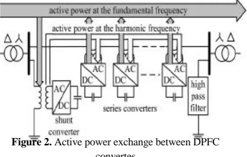
thegrid at a harmonic frequency[9]. Based on this fact, a shuntconverter in DPFC can absorb the active power in onefrequency and generates output power in another frequency,and also according to the amount of active power required atthe fundamental frequency, the DPFC series convertergenerate the voltage at the harmonic frequency there byabsorbing the active power from harmonic components.Assume a DPFC is placed in a transmission line of a two-bus system, as shown in Fig.1. While the power supply generatesthe active power, the shunt converter has the capability toabsorb power in fundamental frequency of current. In thethree phase system, the third harmonic in each phase isidentical which is referred to as “zero sequence”. The zerosequence harmonic can be naturally blocked by Y-∆ transformer.
So the third harmonic component is trapped in Y-∆ transformer [6]. Output terminal of the shunt converter injectsthe third harmonic current into the neutral of ∆Ytransformer. Consequently, the harmonic current flowsthrough the transmission line. This harmonic current controlsthe DC voltage of series capacitors. Fig. 2 illustrates how theactive power is exchanged between the shunt and seriesconverters in the DPFC. The thirdharmonic is selected toexchange the active power in the DPFC and a highpass filteris required to make a closed loop for the harmonic current.
Figure 2. Active power exchange between DPFC convertes
B. The DPFC Advantages
The DPFC in comparison with UPFC has som eadvantages, as follows:
The DPFC similar to UPFC, can control all parameters of transmission network, such as line impedance, trans mission angle, and bus voltage magnitude.
b) High Reliability
The series converters redundancy increases the DPF Creliability during converters operation [7]. It mens, if one ofseries converters fails, the others cancontinue to work.
c) Low Cost
The single-phase series converters rating are lower than one three-phase converter. Furthermore, the series converters do not need any high voltage isolation in transmission line connecting; singleurn transformers can be used to hang the series converters. Reference [6] reported a case study to explore the feasibility of the DPFC, where a UPFS is replaced with a DPFC in the Korea electric power corporation [KEPCO]. To achieve the same UPFC control capability, the DPFC construction requires less material [6].
2. DPFC Control
The DPFC has three control strategies: central controll er,series control, and shunt control, as shown in Fig. 3.
A. Central Control
This controller manages all the series and shunt controll ersand sends reference signals to both of them.
B. Series Control
Each single phase converter has its own series control through the line. The controller inputs are seris capacitor voltages, line current, and series voltage reference in the dqframe. The block diagram of the series converters in Matlab/Simulink environment is demonstrated in Fig. 4.
Figure 3. DPFC Control Structure
Figure 4. Block diagram of the series converters in Matlab/Simulink
Any series controller has a lowpass and a 3rdpass filter tocreate fundamental and third harmonic current, respectively.Two singlephase phase lock loop (PLL) are used to takefrequency and phase information from network[8].Theblock diagram of series controller in Matlab/ Simulink isshown in Fig. 5. The PWMGenerator block manages switching processes.
Figure 5. Block diagram of series control structure in Matlab/Simulink
C. Shunt Control
Figure 6. The shunt control configuration: (a) for fundam ental frequency (b) for third-harmonic frequency
III.
RESULTS AND DISCUSSION
Power Quality Improvement
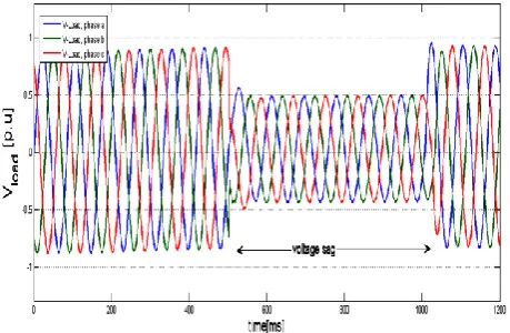
The system is in under study. The system contains a three-phase source connected to a nonlinear RLC load through parallel transmission lines with the same lengths. The DPFC is placed in transmission line, which the shunt converter is connected to the transmission line in parallel through a Y-Δ three-phase transformer, and series converters is distributed through this line. To simulate the dynamic performance, a three phase fault is considered near the load. The time duration of the fault is 0.5 seconds (500-1000 millisecond) [9][1]. As shown in Fig. 7, significant voltage sag is observable during the fault, without any compensation. The voltage sag value is about 0.5 per unit. After adding a DPFC, load voltage sag can be mitigated effectively, as shown in Fig. 8. [1][2]
Figure 7. Three-phase load voltage sag waveform
Figure 8: Mitigation of three phase load voltage sag with DPFC
Fig. 9 depicts the load current swell about 1.1 per unit, during the fault. After implementation of the DPFC, the load current swell is removed effectively. The current swell mitigation for this case can be observed from Fig. 10 [1].
Figure 9 : Three Phase Load Current Swell Waveform Without DPFC
Figure 10 : Mitigation of three-phase load current swell with DPFC
the voltage sag and swell mitigation, using a new FACTS device called distributed power flow controller (DPFC) is presented. The DPFC structure is similar to unified power flow controller (UPFC). It has a same control capability to balance the line parameters like transmission angle, line impedance and bus voltage magnitude. However, the DPFC has some advantages, as compare to UPFC, such as high reliability, high control capability and low cost. The DPFC is modelled and three control loops, i.e., central controller, series control, and shunt control are design. The system under study is a single machine infinite-bus system, with and without DPFC. It is shown that the DPFC gives an acceptable performance in power quality mitigation and power flow control.
Table 1: Simulation system parameter
Parameter Values
Three Phase Source
Rated Voltage 220KV Rated Power/ Frequency 100
MW/60Hz
X/R 3
Short Circuit Capacity 11000MW Transmission Line
Resistance 0.012 Pu/Km Length of Transmission Line 100km
Shunt Converter 3-phase
Nominal Power 60 MVAR DC Link Capacitor 600 µF Coupling Transformer (shunt)
Nominal Power 100 MVA Rated Voltage 220/15 KV Series Converter
Nominal Power 6 KVAR Rated Voltage 6 KV Three –phase Fault
Type ABC-G
Ground Resistance 0.01Ω
IV.
CONCLUSION
The proposed payment system combines the Iris recognition with the visual cryptography by which customer data privacy can be obtained and prevents theft through phishing attack [8]. This method provides best for legitimate user identification. This method can
also be implemented in computers using external iris recognition devices.
V.
REFERENCES
[1] Alexander Eigels Emanuel, John A. McNeill
"Electric Power Quality".Annu. Rev. Energy Environ 1997, pp. 263-303.
[2] I Nita R.Patne,krishna L.thakre "Factor Affecting
Characteristicsof voltage sag due to fault in the
power system"serbian journalof Electrical
Engineering vol.5no.1 may 2008,pp.171-182
[3] J. R. Enslin, "Unified approach to power quality
mitigation," in Proc.IEEE Int. Symp. Industrial Electronics (ISIE ’98), vol. 1, 1998, pp. 8–20.
[4] B. Singh, K. AlHaddad, and A. Chandra, "A
review of active filters forpower quality improvement," IEEE Trans. Ind. Electron. vol. 46, no. 5 pp. 960–971, 1999.
[5] M. A. Hannan and Azah Mohamed, member IEEE,
" PSCAD/EMTDCSimulation of Unified
Series-Shunt -Compensator for Power Quality
Improvement", IEEE Transactions on Power Delivery, vol. 20, no. 2,April 2005.
[6] zhihui yuan,sjoerd W.H de haan and Braham
Frreira and Daliborcevoric "A FACTS DEVICE: Distributed power flow controller (DPFC) " IEEE
transaction on power
electronicsvol.25,no.10october 2010.
[7] zhihui yuan,sjoerd W.H de haan and Braham
Frreira "DPFCcontrol during the shunt converter failure" IEEE transaction on power electronics 2009
[8] R. Zhang, M. Cardinal, P. Szczesny and M. Dame.
"A grid simulatorwith control of single-phase power converters in D.Q rotating frame", Power Electronics Specialists Conference, IEEE 2002.
[9] Bhim Singh, Kamal Haddad, October 1999, "A