* To whom all correspondence should be addressed. E-mail: [email protected]
Use of Numerical Method for Determination of
Contact Points Position in Roller Screw Threads
Mikhail Evgenievich Fedosovsky1, Sergei Andreevich Aleksanin1
and Roman Vladimirovich Puctozerov2
1State Institute of Technology Saint-Petersburg Russia,
Russian Federation,190013, Saint Petersburg, Moskovsky prospect, 26, Russian.
2Baltic State Technical University «VOENMEH» named after D.F.Ustinov,
Russian Federation, 190005, Saint Petersburg, str 1 Krasnoarmeyskaya ,1, Russian. DOI: http://dx.doi.org/10.13005/bbra/1717
(Received: 10 February 2015; accepted: 13 March 2015)
This article proposes a versatile numerical method for determining position of initial contact points between rollers, screw and nut in different types of roller-screws characterized by the contact search by the one side of the thread, the possibility to change the workpiece diameter or interaxle distance according to the basis of construction. finding the real dimensions of the part, as well as its positive or negative allowance demands only one iteration. The features of roller screws, affecting the position of initial contact points in transmission mating threaded surfaces are considered in article. Examples on points of contact position calculations are provided for different types of roller screws. These calculations were accomplished with the help of special software developed on the basis of the method.
Key words: Planetary roller screws, The numerical algorithm, Points of contact position, CAD system.
Linear actuators are mechanisms to convert electrical energy into rotary motion by a motor, and then the rotary motion into linear movement by the screw mechanism. Numerous screw mechanisms exist on the market of actuators, but all of them can be divided into two major groups:
a) Actuators with rotating nut and linearly
moving screw;
b) Actuators with rotating screw and linearly
moving nut (Blinov & Ryakhovskiy, 2008). Ball-screws or roller-screws are most used
mechanisms for converting rotary motion into linear. Roller-screw transmissions have several major advantages comparing to other types of transmissions. They are: high efficiency, positioning accuracy, better load capacity and axial stiffness in equal dimensions (Ephremova, 1971; Kozyrev, 1995; Pavlov, 1986).
The use of different roller-screw transmission schemes significantly expands the range of transfer functions, which makes it possible to obtain different dynamic and speed combinations. Wide range of applications and satisfaction of various technical requirements become possible due to roller-screw features. Wide range of transfer functions also makes possible to dispense any intermediate gear, which in turn reduces actuator weight-dimensional characteristics, number of kinematic chain links and as a consequence - the cost of the final product (Pustozerov, 2013).
Planetary roller-screw with short rollers is a kind of transmission with support nut. This design was invented by Strandgrenom (Kozyrev, 2004; Kudryavtsev, 1980) in 1950 and is manufactured by several high-tech companies. Roller-screw transmission contains intermediate rolling bodies (threaded roller satellites) - the same as similar design roller bearings. Rollers are operating between the screw and nut, which has multiple triangular thread with straight lines profile. Rollers thread profile has a dome shape formed by radial arc. Roller thread has the same length as nut thread. Rollers thread has also the same angle as nut thread, therefore to prevent axial movement of the rollers relative to the nut. To have equal thread angle on nut and rollers the ratio of their thread starts is equal to the ratio of their thread average diameters. Rollers make planetary motion when nut or screw are rotating. To make rollers roll in the nut without slipping, as well as to ensure coaxial movement of screws and rollers, ring gears are cut on the ends of rollers to match with nut ring gear. To avoid change of transfer function of the transmission by slipping of the rollers thread relative to screw thread, the number of screw thread entries is equal to the number of thread nuts. Thus the transfer function is determined by the angle of the screw thread. Rollers pins are settled in separator which provide constant relative position of rollers around the circumference. Screw thread angle differs from the rollers thread angle, which leads to axial movement of the screw relative to the nut and rollers.
Roller-screws have several important advantages, but to achieve them complex engineering design and manufacturing technology issues should be solved. While the process of
design, it is important to take into account correctly roller-screw kinematic features and the nature of the internal force interactions (Kozyrev, 1983a; Kozyrev, 1983b).
Roller-screws properties are characterized by the following basic parameters:
a) Transfer function;
b) Static load;
c) Lifetime;
d) Kinematic accuracy;
e) Efficiency;
f) Axial stiffness.
The major feature of roller-screws is an ability to make multiple contacts between screw, nut and rollers thread turns (Margolin, 1970; Ryakhovskiy & Blinov, 2002). The axial load is transmitted through the contact surface in the inner threaded engagement of rollers with nut and external threaded engagement of rollers with screw. Since the profiles of the screw and nut threads is triangle (formed by the straight lines), and rollers thread profile is dome shaped (formed by a circular arc), the initial contact in the place of engagement is a sort of point contact. The position of the contact point depends on the thread angles value of matching threaded parts. Axial load results in appearance of contact area with irregular shape. Size, shape and position of the contact area is determined by contact place load value and geometry of contacting surfaces. It is also necessary to take into account that load distribution on thread turns will be unequal due to unavoidable manufacturing faults in thread machining process. While applied load rises the quantity of interacting thread turns increases and axial rigidity of the whole transmission increases as consequence. Roller-screw kinematic error is formed by accumulated and periodic faults and is mainly due to manufacturing faults of the thread pitch (Blinov & Krylov, 2006; Morozov & Panyuhin, 2000).
and profile angles of the nut and rollers is mandatory requirement for normal operation.
This ensures absence of edge contact in engagements when axial movement of rollers relative to the nut is happening. In this case, contact point is situated in an axial plane, on rollers and nut reference diameters contact line. Thread angles of screw and rollers are different – so the contact point is shifted.
Mutual placement of thread turns which is necessary to accomplish roller-screw assembly requires increase of the distance between screw and roller axis or diameter reduction of one of the parts (Krainev, 1992; Rechetov, 1974).
Numerical method is the most efficient for point of contact position determining on roller-screw threaded surfaces. As opposed to analytical method, numerical method is not dependent on the thread feature, transmission type and thread profiles form. Thread profiles may be described by any functions. This means that numerical method allows to determine additional axial backlash which occurs in transmission after some time of exploitation due to contacting surfaces thread wear. This fact is all the more so important because of roller-screw distinguishing major features - intense burn-in under load in the early hours.
METHODS
The core of the method is in creation of coordinate grid system in the end plane (in area of roller thread turns contact with screw and rollers thread contact with nut). Let’s consider the contact between roller thread and screw thread as an example. Since all rollers engage equally with the screw and nut, that will be enough to consider just one roller. Let’s create a coordinate system associated with the screw. We introduce the concept of the end plane: the end plane is the plane which is perpendicular to the symmetry axis of screw rotation. Let’s also introduce the concept of the axial plane: axial plane is a plane which is going through symmetry axis of the screw and one of the rollers (Blinov & Ryakhovskiy, 1996).
Let’s draw 0x axis so that it is perpendicular to the axial plane and intersects with the symmetry axis of screw turning. Let’s Draw 0y axis so that it lies at the intersection of the axial plane and the end plane, The end plane is
simultaneously a symmetry plane of an axial profile of the thread screw. Lets draw axis 0z so that it coincides with the symmetry axis of screw rotation. The grid is build up in the plane xy, i.e. in the end plane. Than in each grid node radius vector is lead from centers of screw and roller. Lengths of the radius vectors are calculated according to the following expressions:
, ...(1)
, ...(2)
wherein xov, yov, are coordinates of screw axis
xov, yor are coordinates of roller axis,
xk, ykare coordinates of grid junction
The rollers are arranged around the screw in such a manner that their symmetry rotation axis are parallel to the symmetry rotation axis of the rotor. Symmetry rotation axis of all the rollers inside roller-screw are at the same distance from the screw symmetry rotation axis. This distance is called interaxial distance (Bushenin & Deulin, 1979). According to all written above screw and roller axes coordinates can be found from the following expressions:
Xov = 0 ...(3)
Yov = 0 ...(4)
Xor = 0 ...(5)
Yor = w ...(6) Since the algorithm is numerical, special software based on it was supposed to be created. Despite the ever-increasing speed of modern computers, special attention to the code optimization should be paid when create programs. Therefore, data from which the results can be obtained should be used in calculation only. In our case, coordinates of the grid, which could potentially be points of contact coordinates (between screw and roller thread) should be used only. Following conditions should be accomplished to make grid node lie in area of potential contact:
rv [0.5, Dwv, 0.5 . Dav] ...(7)
rr [0.5, Dwv, 0.5 . Dar], ...(8)
where in Dwv is screw thread root diameter, Dav- screw thread crest diameter,
Dwr – roller thread root diameter, Dar - roller thread crest diameter,
of the screw to the point of a grid node,
rr- the length of the radius vector from the center of the roller to the point of a grid node,
Further in calculation, only the grid nodes that fulfill these conditions are taken into consideration. Then angles between radius-vectors and axis Oy should be determined:
= arcsin (xk / rv), ...(9)
= arcsin (xk / rr), ...(10)
Wherein is the angle between the
radius vector drawn from the center point of the screw to the point of a grid node and the axis Oy,
r is the angle between the radius vector drawn
from the center of the roller to the point of a grid node and the axis Oy.
Thread profiles in the axial section are described by function z'(r). Consequently, the coordinates of z' for the screw and roller
corresponding to the radius-vectors obtained can be determined. As thread profiles are symmetrical, coordinates of threads contacting sides are considered in calculation. In our case, the right side of the screw thread turn is contacting with the left side of the roller thread turn.
One turn of the thread result in shift of the axial point on the value of thread lead:
Pv = t . nv, ...(11)
Pr = t . nr ...(12) where in t is the thread pitch,
nv is the number of screw thread entries
nr is the number of roller thread entries
When thread is right-hand, its turn is shifts to direction of the axial coordinate increase. And opposite, when thread is left-hand, its turn shifts to the direction of the axial coordinate decrease. We assume positive number of thread
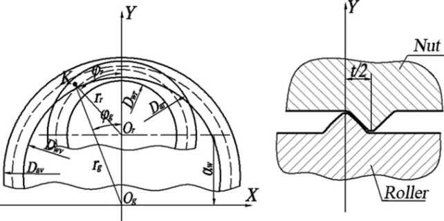
Fig. 1. Contact between screw and roller. K doesn’t belong to the axial plane of YOZ
entries on right-hand threads and negative on left-hand threads when determine the value of thread lead. Consequently, when axial section rotates to the angle, thread turn is axially shifting along the helix on the value of P . / (2.) . It is also necessary to take into account that symmetry planes of the screw and roller axial profiles are half-pitch away from each other. Screw and roller thread shape coordinates (taking into account shift) are determined by following formulas:
Zv = z'v + Pv/ (2.) ...(13) Zr = z'r + Pr/ (2.) ...(14)
Where in z'v is a screw thread shape
coordinate in axial plane
z'r is a roller thread shape coordinate in axial plane These screws and roller thread shape coordinates should be determined for all grid nodes
that belong to area of possible thread turns contact. Then the difference between the coordinates of the screw and roller is determined:
dz = zv - zr ...(15)
It is necessary to find the minimum value to determine point coordinates where screw and roller thread turns have the minimum distance between each other. This value is an axial clearance between thread turns. Negative axial clearance means that roller thread turns can’t be placed in the roots between screw thread turns, i.e. there is tightness between these parts. Positive axial clearance means that roller thread turns are placed easily in the roots between screw thread turns, i.e. there is axial backlash between these parts.
Zero axial clearance means a touch between thread turns, without any tension or backlash.
Fig. 3. Geometry of the roller-screw with support nut
Coordinates of the contact points between roller and nuts are determined similarly.
Let’s draw 0x axis so that it is perpendicular to the axial plane and intersects with the axis of the nut rotational symmetry. Let’s draw 0y axis so that it lies at the intersection of the axial plane and the end plane, and the end plane is at the same time a symmetry plane of nut axial thread turn profile. Let’s draw axis 0z so that it coincides with the axis of nut rotational symmetry. The grid is built in the plane xy, i.e. in the end plane. Then radius vectors are drawn from the centers of the nut and the roller into each grid node. The lengths of the radius vectors are determined with the help of following formulas:
, ...(16)
, ...(17) wherein xog,yog are coordinates of the screw axis,
xor,yor are coordinates of the roller axis, xk,yk are grid nodes coordinates.
Nut and roller axes coordinates should be determined from the following expressions:
Xog = 0, ...(18)
Yog = 0, ...(19)
Xor = 0, ...(20)
Yor= aw ...(21) In our calculations we should only use coordinates of the grid nodes, which could potentially be contact points coordinates (between nut and roller threads) - the same as in case of screw and roller thread turns contacts. Grid node which conforms to the following conditions lies in area of potential contact:
rg [0.5, Dwg, 0.5 . Dag] ...(22)
rr [0.5, Dwr, 0.5 . Dar] ...(23)
wherein Dwg – nut thread root diameter, Dag - nut thread crest diameter,
Dwr – roller thread root diameter, Dar - roller thread crest diameter.
rg- the length of the radius vector from the center of the nut to the point of a grid node,
rr- the length of the radius vector from the center of the roller to the point of a grid node,
Only the grid nodes that fulfill these conditions are taken into consideration in further calculation. Then angles between radius-vectors and axis Oy are determined:
g= arcsin (xk / rg), ...(24)
r= arcsin (xk / rr), ...(25)
Where in g - the angle between the radius vector drawn from the center point of the nut to the point of a grid node and the axis Oy,
r - the angle between the radius vector drawn
from the center of the roller to the point of a grid node and the axis Oy.
We should take into account in calculations coordinates of threads contacting sides due to symmetric property of thread profiles. In our case, the left side of the nut thread turn is contacting with the right side of the roller thread turn.
One turn of the thread result in the axial point shift on the value of thread lead:
Pg = t . ng, ...(26)
Pr = t . nr, ...(27) where in t is the thread pitch,
ng is the number of nut thread entries nr is the number of roller thread entries
Nut and roller thread shape coordinates (taking shift into account) are determined with the help of the following formulas:
Zg = z'g + Pgg / (2.) ...(28)
Zr = z'r + Pr/ (2.) ...(29)
wherein z'g is a nut thread shape
coordinate in axial plane,
z'r is a roller thread shape coordinate in axial plane.
These nut and roller thread shape coordinates should be determined for all grid nodes which lie in area of possible thread turns contact. Then the difference between the coordinates of the screw and roller should be determined according to the following formula:
dz = zv - zr ...(25)
Fig. 5. Geometry of the roller-screw with support screw
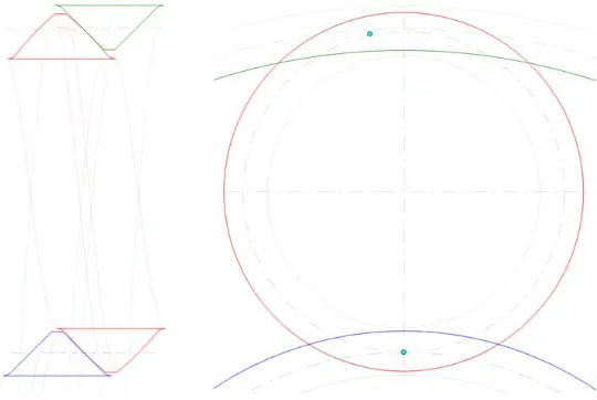
Fig. 6. Contact in inverted type roller-screw
(Ryakhovskiy & Blinov, 1997). For example, nut and rollers thread angles should be equal when design roller-screw of support nut type. Since the thread angle depends on the thread diameter, any change of the nut or rollers thread diameters are prohibitive. Only the interaxle distance can be changed. Therefore, we first determined the contact point between the nut and the roller. Desired axial clearance value is achieved by interaxle distance change. And only after this point of contact between roller and screw is determined and desired value of the axial clearance is provided by screw thread diameter change. Thus we remain kinematic properties of the reducer and the screw acts as a master link (Kozyrev, 1997).
Screw and rollers thread angles should
be equal when design inverted type roller-screw. Since the thread angle depends on the thread diameter, any change of the screw or rollers thread diameters is prohibitive. Only the interaxle distance can be changed. Therefore, we first determined the contact point between the screw and the roller. Desired axial clearance value is achieved by interaxle distance change. And only after this point of contact between roller and nut is determined and desired value of the axial clearance is provided by nut thread diameter change. Thus we remain kinematic properties of the reducer and the nut acts as a master link (Sokolov, 1997).
lead to inaccurate calculation results, too small values of incrementation take too long time. Therefore, the best choice is the variable increment value which is decreasing with the larger number of iterations until the calculated axial clearance value get into permissible limits.
Choice of proper grid size is also of great importance (especially size of a grid cell). There are two possible variants:
1) Initial choice of large cell size with further
decreases of the size while process convergence.
2) Initial choice of large cell size with further
building up of a new grid with smaller cell size in area of the contact point
Practical implementation of the algorithm
On the basis of the algorithm described above special CAD system which allows determine automatically the contact points between roller, screw and nut according to defined geometric parameters has been created. Visual Studio software development environment was used while creating CAD system and the code was written in C#. General view of a roller-screw created with the use of the CAD graphical module is shown in Figure 3. Geometrical parameters of transmission (thread diameter, pitch and angle) are the initial data given to the CAD. All other parameters are selected in automatic mode with ability to make manual adjustment in case of necessity. Calculations of support nut roller-screw with the following parameters were accomplished as a first example:
dv = 30 mm dr = 10 mm
dg = 50 mm t = 4 mm
= 45° nv = 5
nr = 1 ng = 4
wherein is the half-angle of the thread profile in axial section.
Zero axial clearance value was assumed as required, i.e. touch is happening. The calculations resulted in the following coordinates of the contact point between roller and screw:
xk = 1.201 mm yk = 15 mm
Coordinates of the contact point between roller and nut:
xk = 0 mm yk = 25 mm
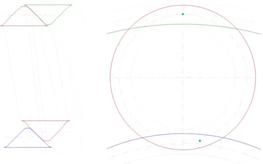
View of a contact in different planes is presented in Figure 4. All the graphics is created automatically in the CAD system.
As seen, the contact point between roller and the nut is in the pole. This is due to the fact that the roller and nut thread angles are equal and threading direction (on these items) coincide. At the same time, the contact point between roller and screw is shifted relative to an axial plane, that is a consequence of screw and roller thread angles inequality. Furthermore, diameter of the screw thread was reduced due to ensure assembly of reducer with required value of the guaranteed axial gap (i.e. setting-up rollers thread turns in the screw thread roots).
d'v = 29.582mm
Calculations of the support screw type roller-screw with the following parameters wese accomplished as the second example:
dv = 30 mm dr = 15 mm
dg = 60 mm t = 5 mm
= 45° nv = -2
nr = 1 ng = -2
As required zero value axial clearance was assumed, i.e. touch is happening. The calculations resulted with the following coordinates of the contact point between roller and screw:
xk = 0 mm,
yk = 15 mm.
Coordinates of the contact point between roller and nut:
xk = 1.579 mm, yk = 29.899 mm
View of a contact in different planes is presented in Figure 6. As seen, the contact point between roller and the screw is in the pole. This is due to the fact that the roller and screw thread angles are equal and threading direction on these items are opposite. At the same time, the contact point between roller and nut is shifted relative to an axial plane, that is a consequence of nut and roller thread angles inequality. Furthermore, diameter of the nut thread was increased to ensure assembly of reducer with required value of the guaranteed axial gap (i.e. setting-up rollers thread turns in the nut thread roots):
DISCUSSION
There is an iterative numerical method of calculating the increment of interaxle distance, similar to the one, described in the article (Blinov & Krylov, 2006). The essence of the method is as follows: for a nominal interaxle distance they check by calculating the distance between the opposite sides of the thread of the screw and matching adjacent turns of the roller’s thread, whether turn of a screw’s thread is located in the cavity formed by the adjacent turns of the roller’s thread. With the positive outcome of verification, calculation, due to finding the unknown quantities, is over and considered to be satisfying. With a negative outcome of verification interaxle distance increases, and repeat of the calculation is performed up to a positive outcome of verification.
Despite the fact that the method is quite convenient and operable, the algorithm described in the article seems to be more efficient and optimized, based on the following:
a) Contact search is performed by the one side
of the thread, as the axial position of the contact parts does not change
b) It is possible according to the basis of
construction to change the workpiece diameter or interaxle distance
c) Finding the real dimensions of the part, as
well as its positive or negative allowance demands only one iteration
CONCLUSION
Roller-screws nowadays are the most promising mechanism for converting rotary motion into linear. These devices are commonly used in electromechanical linear actuators. With the demanding requirements for electromechanical actuators positioning accuracy, kinematic backlash is one of the most important performance criteria. This criteria is a result of the gap between the contacting surfaces of the reducer parts.
Since all the parts of the reducer are made with certain errors, it is necessary to calculate dimension chains, taking into account the tolerances on thread sizes. Then determine the contact in reducer to ensure guaranteed clearance in threaded engagement.
In some cases roller-screw with
guaranteed preload is needed. This problem can be easily solved by identifying the thread contact point with the required tension. This article describes a versatile numerical method for determining the point of initial contact between roller, screw and nut in different roller-screw types. The features of roller screws which affect the initial contact point position in main reducer parts mating threaded surfaces are described. Examples of points of contact coordinates calculations, conducted with the help of CAD system (developed on the basis of the method described) are provided.
Points of contact coordinates determination is an essential issue, but to estimate roller-screw operating properties more complex modeling (which allows to get contact interaction parameters under load) is required. It is necessary to calculate contact pressure and elastic strains under load applied to measure contact stiffness and roller-screw load capacity. Moreover thread machining errors should be taken into account as they influence on load spread between thread turns. All said above proves the necessity of complex numerical algorithm creation.
The article was written in accordance with R&D work “Creating of high-tech production of precision high-performance forceful brand-new electromechanical actuators” in ITMO UNIVERSITY, with financial support from the Russian Federation Ministry of Education and Science, according to the decision of the Russian Federation Government of April 9, 2010 ! 218 “Measures of state support for development of cooperation between Russian universities, research organizations and companies which implement complex projects for high-tech production”.
REFERENCES
1. Blinov, D. S. & Krylov S. I., Planetary roller-screws. Design, calculation methods, Edited by prof. Ryakhovsky O.A. - M .: MGTU. Bauman, 2006; 66-78.
2. Blinov D. S. & Ryakhovskiy O. A., Numerical method for determining the point of initial contact between turns of two screws with parallel axes and different thread angles. MGTU. Bauman, “Mechanical Engineering”, 1996; 3: 93-97.
for rotation into linear movement transformation. Herald for machine building. 2008; 10: 35-40. 4. Bushenin, D. V. & Deulin, E. A., Design of screw
mechanisms: guidelines. Vladimir: Editor VlPI.-1979; 126.
5. Ephremova, G. L., Efficiency determination of the roller-screw mechanisms, Machines gear theory. - M .: Nauka. 1971; 96 - 101.
6. Kozyrev, V. V., The planetary mechanism for converting of rotary motion into linear // Herald for machine building. 1983a; 10: 14-17. 7. Kozyrev, V. V., Comparison of ball and
roller-screws, Herald for machine building. 1983b; 11: 30 - 34.
8. Kozyrev, V. V., Analysis and synthesis of roller-screws as parts of electromechanical actuators: dissertation in engineering Phd. Vladimir, 1995; 408.
9. Kozyrev, V. V., Roller-screws - promising high-tech components for machine-building applications, Drive technology 1997; 5: 28-30. 10. Kozyrev, V. V., Constructions of roller-screws and methods of their design: Vlad. State. Univ. Vladimir, 2004; 8 - 14.
11. Krainev, A. F., Machine parts: dictionary, Herald for machine building, 1992; 480.
12. Kudryavtsev, V. N., Machine parts. L .: Machinery, 1980; 464.
13. Margolin, L. V., Planetary gear screw-nut rolling with threaded rollers, Machines and tools. 1970; 1: 42-43.
14. Morozov, V. V. & Panyuhin, V.I., Rack and helical gears to convert rotational motion into linear, Ed. by Morozov V. V. ,Vladimir University VLGU. 2000; 160.
15. Pavlov B. I., Ball-screw mechanisms in instrumentation. L.: Mechanical Engineering. 1986; 134.
16. Pustozerov R. V., Properties of roller-screw development for the use in linear actuators, Electronic Journal “Scientific Bulletin KSTU” 2013; 2
17. Rechetov D. N., Parts of machines. M .: Mechanical Engineering. 1974; 656.
18. Ryakhovskiy O. A., Blinov D. S., Determining preload of the planetary roller-screw, New Industrial Technology: Industrial and technical journal., 1997; 3: 36-39.
19. Ryakhovskiy O. A., Blinov D. S., Analysis of the planetary roller-screw transmission, Herald Bauman. Mechanical Engineering. 2002; 4: 52-57.