Performance Evaluation for LoRa Transceiver
Ashraf A. Taha1, Mohamed F. Feteiha2 and Wadood Abdul3
1, 3
Department of Computer Engineering, College of Computer and Information Sciences, King Saud University
Riyadh, 11543, Kingdom of Saudi Arabia
1, 2 Networks and Distributed Systems Department, City of Scientific Research and Technological Applications
Alexandria, 21934, Egypt
2 Electrical and Computer Engineering department, Waterloo University, Canada
1[email protected], 2[email protected], 3[email protected]
ABSTRACT
The LoRa (Long Range) defines the physical layer modulation technique that offers a longer range communication link than other challenging technologies, while LoRaWAN is the communication protocol for the network defined by data link (MAC) protocol and its system architecture. LoRaWAN is designed to optimize a Long Range Low Power Wide Area Network (LPWAN) for battery lifetime, capacity, range, and cost. Its concerns on the necessities of the web of things, as a bi-directional communication, mobility and localization services securely and efficiently. In mainly the unlicensed frequencies, it uses direct sequence modulation held in reserve for Industrial, Scientific, and Medical (ISM), for example in Europe (868 MHz) and the United States ranged from (902 MHz to 928 MHz). Network operators can deploy networks without the costly load of frequency licensing. The LoRa modulation is established on the integration of Chirp Spread Spectrum (CSS) which keeps the low power features as Frequency Shift Keying (FSK) modulation and enlarges the link range with Forward error correction (FEC) used for controlling errors in transmission channels. Both of them are essential for modulation. Having different chirp rates is a dominant feature that gives LoRa the ability to demodulate various orthogonal and simultaneous signals at the samilar range of frequency. LoRa Transceiver model is implemented using Matlab - Simulink with fundamental components to demonstrate how reliable elaborate modulation schemes can be built. The paper consists of ….. sections in addition to references. A brief summary about the contents of sections is presented as follow: Section I provides a brief introduction about LPWAN. Section II presents LoRaWAN architecture. Section III describes how LoRaWAN works. Section IV presents implementation of LoRaWAN. Section V presents Challenges and Obstacles. Section VI presents Market Status. Section VII presents LoRaWAN simulation. Section VIII presents the results. Section IX presents the comparison. Section X presents the the conclusion and future work. Finally, a list of references used as background of the paper is presented at the end of the proposal.
Keywords: LoRa Transceiver, Long-range wireless, Low power transmission, Physical layer modulation, Wide area
networks. Stock, a Priori Algorithm and Associaiton Rule Minng.
1. INTRODUCTION
LPWAN networks characterize a relatively new communication model, in which traditional cellular and short-range wireless technologies are complemented by addressing different requests in applications. The underlying technologies propose wide-area connectivity for low power consumption and suitability for low data rate devices with low cost, which is a unique set of features. The market for LPWA networks is also expected to be of a substantial size resulting in the connection of about 30 billion devices to the internet.
LPWAN networks create different balances from traditional technologies, for example, short-range wireless networks (Zig-Bee, Bluetooth), wireless local area networks (Wi-Fi), cellular networks (Global System for Mobile Communications (GSM), Long-Term Evolution (LTE), etc.).
1.1 LPWAN vs. other technologies (pros and cons):
Mass adoption of 2nd generation (2G) and 3rd generation (3G) technologies in cellular networks resulted due to their wide area coverage. Traditional cellular technologies do not achieve energy efficiency to offer extended battery life. The complexity and cost of cellular devices are high due to their ability to cooperate with complex waveforms and they can be increased by optimizing voice, high-speed data services, and text [1].
1.2 LPWAN applications:
LPWA technologies are favorable for power, low-cost, low throughput devices, and allow devices to extend and transfer over wide areas. Internet-of-Things (IoT) and Machine-to-Machine (M2M) devices associated with LPWA technologies can sense and interact with their environment immediately. LPWAN technologies can achieve long range and at low power operation data rate and low latency
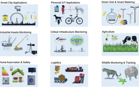
Fig. 1. Applications of LPWA technologies across different sectors [1].
As shown in Figure 1, LPWAN technologies are considered for delay tolerant applications, do not require high data rates, and need low power and cost. LPWAN does not support many industrial IoT, vehicle to vehicle (V2V), and vehicle to infrastructure (V2I) applications. Due to their strict performance requirements, which cannot be ensured with a low cost and low power solution, they require ultra-low latency and ultra-high reliability. This technology can support the requirements of applications for smart cities, smart metering, home automation, and environmental monitoring, etc. This technology can support applications which exchange a small amount of data.
These applications can be classified as follow:
1. Commercial facilities / Buildings / Warehouses: Remote monitoring and control of equipment, operating optimization, employee administration.
2. Homes / Schools / Hospitals / Senior facilities
Senior citizen and child monitoring smart meters (electricity, gas, water)
3. Mountains / Rivers / Oceans
Disaster countermeasures for landslides, flooding, earthquakes, etc.
4. Public Infrastructure
Management prediction and maintenance of infrastructure, street lighting.
5. Cars / Trucks / Buses
Freight and palette management, smart parking, logistics, fleet operation manganite, optimization.
6. Fields / Rice paddies / Ranches
Water quality, soil management, livestock tracking.
2. LoRaWAN ARCHITECTURE
Lora is the physical layer or the wireless modulation used to create the long range communication link. Applying FSK modulation in various wireless systems as the physical layer because it is a very effective modulation for consuming low power [7]. Lora relies on CSS modulation shown in Figure 2, which sustains the similar low power features as FSK modulation but significantly increases the range of communication. Each LoRa symbol is composed of 2-SF chirps, where SF represents the corresponding spreading factor. The use of six orthogonal SFs in the range of 7 to 12, which provide different data rates, results in high spectral efficiency and high network capacity. CSS has many applications in military and space communication for a long time due to the long communication distances that can be attained with strong interference, but the use of Lora is the first commercially viable implementation [2].
Fig. 2. A linear frequency modulated upchirp in the time domain
- Bi-directional communication is permitted by end devices of class A whereby each end device's uplink transmission is followed by two small downlinks receive windows. The scheduling of transmission slot by the end device is dependent on its private communication requests. After the end device has sent an uplink transmission, class A operation is the lowest power end-device system for applications that only need downlink communications from the server in a small period. Automatically, downlink communication from the server is queued until the subsequently scheduled uplink.
- At scheduled periods, Class B devices can open additional receive windows. The end device receives a time synchronized beacon from the gateway to open its own receive window at the scheduled period. When the end device is listening, the server can recognize. - Class C have nearly continuously open receive
windows at its end devices that are only closed when transmitting.
With various protocols, the network can be used in different architectures (Mesh, Star, point to point, etcetera). However, to extend the operable range and take advantage of the increased link budget and also the range capability of LoRa, a star architecture can be used to optimize the network capacity, extend the battery lifetime, and simplify the installation.
LoRa allows sensors to expand their communication range more than 100 km for favorable environment, 15 km for semi-rural area and more than 2 km for dense urban environment with rates from 300 bit/s to 100 Kbit/s [1]. Such a low data rate results in a good sensitivity, which permits for long-range communication of multiple kilometers. In practice, the reasonable operable distance will be shorter due to increased packet-loss ratio for the low data rates while distance increases, this will lead to new hidden challenges.
To this end, LoRa technology solutions can target multiple application domains, such as Internet-of-Things (IoT), machine-to-machine (M2M), device-to-device (D2D), Automated Meter Reading (AMR), wireless alarm, security systems, industrial monitoring and controlling, and long-range irrigation systems.
Lora is significant due to its long-range capability; a single gateway or base station can cover whole cities or hundreds of square kilometers. Range highly relies on the environment or impediments at a given site, but Lora and LoRaWAN have a higher link budget than any other standardized communication technology. The link budget is the main factor in defining the range in a certain environment and typically given in decibels (dB). Entire countries can easily be covered with a minimal amount of
infrastructure. LoRa is a wireless technology mainly used in M2M and IoT. Table I summarizes the LoRa wireless technology key features such as range, standard, modulation scheme, capacity, power consumption and physical layer [3].
LoRaWAN is an LPWAN established and maintained by the Lora Alliance. While the Lora physical layer allows the long-range communication link, it defines the communication protocol and system architecture for the network. The protocol and network architecture determine the battery lifetime of a node, the network capacity, the quality of service, the security, and the applications served by the network.
Secure bi-directional communication, mobility and localization services are the LoRaWAN key necessities of IoT. The description of LoRaWAN gives seamless interoperability within smart Things and gives back the freedom to the user, developer, and businesses without the necessity of complex local installations allowing for the roll-out of the Internet of Things.
The LoRa protocol was established by IoT industry leaders including IBM, Actility, Semtech and Microchip. It is now transferred to the LoRa Alliance. The LoRaWAN architecture includes three main components:
- The end nodes with the low data-rate applications, which are sensing and governing the world connected to one or more gateways.
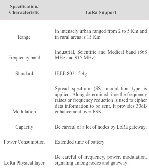
Table 1 : Key Features of Lora wireless Technology
Specification/
Characteristic LoRa Support
Range
In intensely urban ranged from 2 to 5 Km and in rural areas is 15 Km
Frequency band
Industrial, Scientific and Medical band (868 MHz and 915 MHz)
Standard IEEE 802.15.4g
Modulation
Spread spectrum (SS) modulation type is applied. Along determined time the frequency raises or frequency reduction is used to cipher data information to be sent. It provides 30dB enhancement over FSK.
Capacity Be careful of a lot of nodes by LoRa gateway.
Power Consumption Extended time of battery
LoRa Physical layer
- The signals which directed to a network server are collected by gateways.
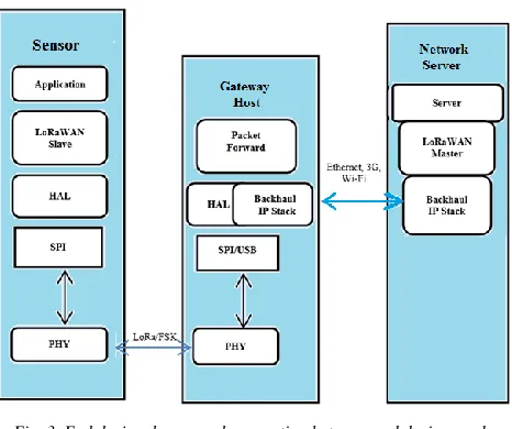
- The responsibility of network server is for authenticating end nodes and discussing the end-to-end coding that is part of the LoRaWAN specification. As shown in Figure 3, LoRaWAN network architecture is represented in a star-of-stars topology. Gateways are a transparent bridge depending messages among end-devices and a central network server. Network servers are connected by gateways through standard IP connections while end-devices are linked to one or many gateways using single-hop wireless communication [4].
Fig. 3. End devises layers and connection between end devices and gateway
A single LoRaWAN Gateway is comparatively cheap and covers more than 10 Km in range. For example, The Thing Network covered the city of Amsterdam using 10 gateways at the cost of 1200 dollars with the advantage of LoRaWAN’s long range.
Security is a big concern in LoRaWAN in such a way that it can be used to build a national network and assist critical building infrastructure of IoT. The Lora Alliance has attempted to increase the security of LoRaWAN by adding three different layers of security:
1- Confirming security on network level using unique network key.
2- Approving end-to-end security on application level using unique Application key.
3- Fixed key of the device.
LoRa based LPWAN looks more promising and is more general although there are other variations for LPWAN like Sigfox [5].
Gateways are a transparent bridge transferring messages among end-devices and a central network server. LoRa gateways (also named LoRa concentrators) are multi-channel, multi-modem transceivers. Because of the
physical properties of LoRa, its gateways can demodulate on multiple channels and multiple signals on the same channel simultaneously. The gateways use different radio frequency components than the end-point to allow high capacity and clearly to enable the gateways to serve like a transparent bridge transferring messages among end-devices and a central network server in the backend. All end-point communication is commonly bidirectional. In addition, it provides operation such as multicast enabling, software upgrade, over the air or other mass delivery messages to decrease the on-air communication time. Different gateways relying on the installation location and the preferred capacity
Data rates of LoRaWAN ranged between 0.3kbps to 11kbps and data rate of one Gaussian Frequency Shift Keying (GFSK) for Europe is 50kbps. The minimum data rate in North America is 0.9kbps. However, the physical specifications are capable of more options. By using different frequency channels and data rates, the communication can spread among end-devices and gateways. The channel and data rate chosen is a trade-off between communication range and message payload. The LoRaWAN network server is managing the data rate and Radio Frequency output for each end-device separately using an adaptive data rate algorithm to maximize both battery life of the end-devices and full network capacity. Under the local radio conditions, this unique optimization relies on advanced link information such as Signal Noise Ratio (SNR), Received Signal Strength Indication (RSSI), and channels to confirm optimal performance. This type of link information is usually used such that instant synchronization dynamically adapts the spreading factor and coding rate to the actual link budget. A connectivity comparison to existing wireless technologies is illustrated in Figure 2. The end-device changes channel in a pseudo-random fashion every 19 transmissions to mitigate the possible interferences. The frequency range result can make the system more resistant to interference.
Lora network elements
Endpoints:
The elements of LoRa network are usually remotely positioned where the sensing or the controlling is assumed [6].Lora gateway:
The gateway sends the communications onto the backhaul system after accepting them from the Lora endpoints and this Lora network portion can be Ethernet, cellular or any other telecommunications link wired or wireless. Using standard IP connections, the gateways are linked to the network server. By this way, the data uses a standard protocol, but can be connected to public or private telecommunications network. Lora gateways may often be co-located with a cellular base station which prove the similarity of a Lora network to that of a cellular one. Gateways can use spare capacity on the backhaul network.Server:
The Lora network server manages the network, it acts to delete duplicate packets, schedules acknowledgment, and adapts data rates. Considering the way in which it can be deployed and connected, makes it very simple to deploy a Lora network.Fig. 4. Structure of LoRaWAN
Remote computer: Lora network is a transparent in which a remote computer can then control the actions of the endpoints or collect data from them.
3. HOW IT WORKS
LoRaWAN is connected in a star network topology where all sensors have LoRa chips to transmit messages to gateways and not to other sensors. Therefore, gateways can pass along the messages with cellular, satellite, Ethernet, or Wi-Fi to a network server. The duplicate messages that are sent by multiple gateways will be eliminated by the network server. Messages are sent from the server via the gateway to the sensors to update firmware and approve received messages.
3.1 LoraWAN Protocols
By the LoRa Alliance, LoRaWAN is a protocol specification built on top of the LoRa technology. To enable low power, wide area communication between
remote sensors and gateways linked to the network, LoRaWAN uses unlicensed radio spectrum in ISM bands.
3.2 Where does LPWAN Fit?
All the expected applications and volumes for IoT cannot be served by one technology. Wi-Fi and Bluetooth Low Energy (BTLE) technologies are widely adopted standards and the applications related to communicating personal devices are served. Cellular technology is a great fit for applications in which high data throughput and a power source are required.
Fig. 5. Wireless segments tradeoff
LPWAN presents long battery lifetime and is designed for sensors and applications that require to transmit small amounts of data a few times for every hour over long distances from varying locations [7]. The following table II describe the key features for LoraWAN protocol.
4. IMPLEMENTATION OVERVIEW
The LoRa Alliance details the protocol as:
LoRaWAN is an implementation for a server-side of several access protocols designed to decrease collisions with a huge number of endpoints.
Customer logic is constructed into the network server, making LoRa operate in a centralized network architecture.
Gateways within the same network require synchronization.
Allowing passive geolocation of things, without requiring any GPS which is embedded into objects. Antenna diversity can be deployed since all gateways
network locating nodes position, even when they are mobile.
Extending the communication between end-devices and gateways on diverse frequency channels and data rates. The trade-off data rate is chosen between communication range and message period.
Increasing capacity of gateway using different data rates do not interfere and creates group of “virtual” channels.
The data rate and RF output for each end-device individually are managed using the LoRaWAN network server by means of the Adaptive Date Rate (ADR) scheme which updated every 24 hours.
LoRa is bidirectional, allowing sensors to transmit and receive (i.e., communicate through uplink and downlink directions, respectively).
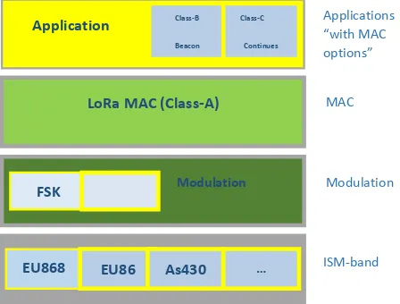
Different types and categories of sensors (Classes A, B, and C) are offered, which is further considered as an added value services to the industry as summarized in Table III and Figure 6.
In general, all communication is bi-directional. However, the major traffic estimates the uplink communication from an end-device to the network server.
Fig. 6. Basic LoRaWAN in class A and optional features in class B and C
The end-device select the channel in a pseudo-random way for every transmission. The consequential frequency diversity further makes the system more influence to interferences.
LoRa is well suited for sending small amounts of data, and is ideal for low power applications using battery-operated sensors communicating over long range links. Over the range of the network, because of synchronization and hops, a mesh network can spread but comes at the cost of decreased network capacity, synchronization overhead, and decreased battery lifetime. However, a star architecture can be used to improve the network capacity, battery lifetime, and installation ease by the increased link budget and range capability of LoRa. Using a wide bandwidth to send a low rate signal and a modulation format that does not tolerate any activity in the used bandwidth becomes a significant issue for capacity especially in a long-range network. In addition, the network will be very vulnerable to interference. However, it all depends on the application. For example, if a sensor sends a small amount of data every hour, LoRa is a better solution.
Using Few base stations, and care of thousands of nodes as in mesh network can cover entire cities or countries, therefore, IoT with least infrastructure investment is high concern, ensuring better opportunities for customers. If
Application
LoRa MAC (Class-A)
Modulation FSK
EU868 EU86
8
As430 …
Class-B
Beacon
Class-C
Continues
Applications “with MAC options”
MAC
Modulation
ISM-band
Table 2: Lora Technology and LoraWAN Protocol Key Features [3]
Geolocation GPS-free, low power tracking applications are allowed.
Low cost Reduction iof costs by three ways: infrastructure investment, operating expenses and end-node sensors. Standardized Enhanced speeds adoption of global
interoperability and roll out of
LoRaWAN-based networks and
Internet of Things applications. Low power Designed for low power consumption
to extend battery lifetime up to 20 years.
Long range Single base station provides deep penetration in dense urban/indoor regions, connects rural areas up to 48.3 kilometers away.
Secure End-to-end AES128 encryption is embedded.
High capacity Millions of messages are supported per base station, ideal for public network operators serving many customers.
Table 3: LoraWAN device classes
Class name Intended usage
A (all) Battery powered sensors, or actuators with no latency constraint.
Most energy efficient communication class. Must be supported by all devices.
B (beacon) Battery powered actuators, an energy efficient communication class for latency controlled downlink based on slotted communication synchronized with a network beacon.
cellular networks are ineffective, while Wi-Fi, ZigBee or Bluetooth features of networking are not enough, a LoRa solution can be initiated to fit the requirements. The gap between current LAN and WAN/Cellular technologies is neglected using LoRa.
LoRa allows minimizing energy consumption at the end-to-end links as well as at the end-points by optimizing bandwidth and power resulting in the nodes experiencing a longer battery life.
Chirp modulation helps LoRa wireless link to achieve sensitivity up to -137 dBm and up to 157 dB of link budget (as claimed by LoRa Alliance). The trade-off in the range of Kbps is the achievable data rate. This defines the applicability of the technology to IoT, M2M and home automation applications. It is not currently suited for video streaming.
Further field and designated sites experimental work needs to be initiated to fully understand the protocol and confirm its specifications and capabilities. A significant amount of development work is required to build a LoRa system or network. LoRa is an emerging solution when compared to well-established standards, e.g., Wi-Fi, ZigBee, Bluetooth, Cellular, etcetera. Like most new networking technologies, LoRa has not yet settled into a standard protocol that everyone agrees upon. To list some
examples:
The transmission of multicast messages from a network server to many end-devices is not defined by the candidate specification for the LoRa Alliance protocol.
Keeping consistency and correctness of messages using Cyclic Redundancy Check (CRC) in LoRa uplink which supports data integrity, to confirm that the received data in transit is not changed either by an intentional illegitimate access or by noise. CRC for the most cases can handle unintentional process; on the other hand, it is incapable to cope with the
intended data alteration because after changing the data, the unauthorized intruder can produce the same CRC of the source node. The aggregation result must be confirmed before accepting it as data aggregation result for such enormous long-range network is used for critical decision making. A large amount of resources are consumed using data privacy and integrity protection processes (i.e., limited power) of LoRa nodes, it is an essential to devise and deploy a light-weight integrity technique, which can attain data privacy and integrity security for such type of networks.
At the downlink level, to keep messages short with lowest effect on any duty-cycle limitations of the ISM bands used, no data integrity check is done. To change from Class A to B, the decision comes
from the application layer of the end-device. If the network side controls the switching from class A to Class B, the customer application uses one of the end devices Class A uplink to send back a downlink to the application layer, and the application layer identifies this demand on the end-device, the LoRaWAN level does not manage the described process.
The network server is informed by a mobile end device of its position periodically to update the route of downlink. Optimally, for more efficiency, it is better if the application discovers that the node is moving by analyzing the beacon content. To avoid systematic uplink collisions, the end-device must apply a random latency between the beacon reception and the uplink transmission.
Messages can be unicast when the messages are sent to a single end-device or multicast when the messages are sent to multiple end-devices. For multicast group, all devices must share the same multicast address with associated encryption keys. The methods remotely setup are not identified by the LoRaWAN Class B specification.
3.3 Network Setup
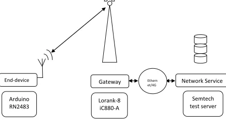
To collect measurements of signal strength when we have one gateway and one end-device have been used. The gateway consists of a Beagle bone Black controlling an iC880A concentrator module from IMST and acts as a host for the concentrator, which forwards any traffic from LoRa network onto a wired Ethernet connection in the case of uplink messages, and vice versa for downlink messages. To modulate the symbol stream, and handle up to eight links simultaneously, the iC880A board uses a Semtech SX1301 baseband processor.
An Arduino based solution is used for end nodes. The setup consists of an Arduino Uno, paired with a LoRaWAN module from Labellum. Both of them linked through a multi-protocol shield from the same company. Table 4: LoraWAN device classes
Class name Intended usage
A (all) Battery powered sensors, or actuators with no latency constraint.
Most energy efficient communication class. Must be supported by all devices.
B (beacon) Battery powered actuators, an energy efficient communication class for latency controlled downlink based on slotted communication synchronized with a network beacon.
The RN2483 board from Microchip is the basis of the LoRaWAN module. For the sole purpose of sending uplink messages, this end-device has been programmed as a Class A device. The network back-end consists of a server hosted by Semtech for testing purpose, where both transmission content and metadata can be downloaded. Any device can extract parameters such as RSS, SNR, SF and Bandwidth (BW) of the signal [2].
Fig. 7. Network map of implemented LoRaWAN setup.
3.4 Gathering RSS measurements
Both gateway and end-device are located within an office area to collect indoor measurements. The office area has a typical open layout with a partition type design and used for testing. Several measurement sequences are collected at different distances by interchanging the location of the end-device. Multiple measurements series are gathered to test and confirm the long distance path loss model at certain distances. The measurement data is then used to calculate the model parameters, which will be used to control the distance between gateway and end-devices in the simulation. The RSS are presented as integers in dbm scale in measurements [2].
To address the different requirements reflected in the wide range of applications, LoRaWAN has various different classes of end-point devices.
Class A - Bi-directional end-devices:
Bi-directional communication is allowed for end-devices of Class A whereby two short downlinks receive windows follows each end-device’s uplink transmission. The end-device schedules the transmission slot which is established on its own communication requirements with a small difference based on a random time basis (ALOHA protocol). After the end-device has sent an uplink transmission, this Class A operation is the lowest power end-device system for applications that only need downlink communication from the server. At any other time, downlink communications from the server will have to delay until the next scheduled uplink.
Class B - Bi-directional end-devices with scheduled
slots:
Class B devices open extra receive windows at scheduled times. In addition to Class A. random accept windows in
a time synchronized Beacon from the gateway in order for the end-device to open its receive window at the scheduled time. When the end-device is listening, this agrees the server to know.
Class C - Bi-directional end-devices with highest
receive slots:
End-devices of Class C have close transmit windows, nearly continuously opened when receiving.
5. CHALLENGES AND OBSTACLES
New technologies for data connectivity:
Without using 3G or Wi-Fi, new data network technologies permit for things to join to the internet. LoRaWAN is one of these technologies which is suitable for the IoT with low battery, long range, and low bandwidth. Imagine a network that can be used without cumbersome Wi-Fi passwords, mobile subscriptions, and zero setup costs [8].
Low costs:
Covering a whole city can be done with a small investment because the cost of the equipment is low and the impact is very high. For example, Amsterdam city was covered by only 10 gateways with each one costing 1200 dollars [8].
Crowd sourced:
To construct such a network, it has to base on large telecom corporations because the costs are not expensive. Instead, without any form of subscription, it can crowd source the network and make it public. Our goal is to enable a network by the users for the users [8].
LoRaWAN has capacity and interference challenges
1.When a gateway is transmitting, all gateway receive channels are disabled, thereby making it half-duplex only. End-device Arduino RN2483 Gateway Lorank-8 iC880-A Network Service Semtech test server Ethern et/4G etc.
Table 5: Market Status Europe North
America
China Korea Japan India
Frequency band 867-869MHz 908-928MHz 470-510MHz 920-925MHz 920-925MHz 865-867MHz Channels 10 64+8+8
In definition by technical committee Channel BW up 125/250 KHz 125/250KH z Channel BW dn
125KHz 500KHz
TX power up
+14dBm +20dBm-typ(+30dbm
is allowed TX power
dn
+14dBm +27dBm
SF up 7-12 7-10 Data rate
250bps-50kbps 980bps-21.9kbps Link
budget up
155db 154db
Link budget dn
2.Testing shows LoRaWAN’s MAC efficiency is only in the 18-22% range.
LoRaWAN has significant security and privacy risks
1.Public key handshaking cannot be executed safely via LoRaWAN due to networking limitations. 2.All encryption is handled using static keys, such as
SIM cards.
3.LoRaWAN beacon mode is easily detected.
LoRaWAN does not support multi-hop
1. LoRaWAN does not support multi-hop networking. 2. LoRaWAN does not support mesh networking. 3. LoRaWAN does not support P2P networking.
6. MARKET STATUS
LoRaWAN design differs slightly from region to region relied on regulatory requests and the different regional band allocations. For Europe and North America the LoRaWAN plan are distinct, but the technical committee is still describing other areas. As a contributor member and sharing in the technical committee, linking the LoRa Alliance can have important benefits to companies for the Asia market as targeting solutions [7].
LoRaWAN for Europe
For Europe, LoRaWAN specifices 10 channels, one high data rate LoRaWAN channel at 11kbps, another for FSK channel at 50kbps and eight channels for multi data rate range from 250 to 5.5 kbps. With the exception of the G3 band that permits +27dBm, the maximum output power allowed by European Telecommunications Standards Institute (ETSI) is +14dBM. With no maximum transmission, there are duty cycle limitations under ETSI.
LoRaWAN for North America
For North America, the ISM band is from 902-928MHz. LoRaWAN specifies 64 and 125kHz uplink channels (902.3 to 914.9) MHz in 200kHz increases. In 1.6MHz, there are an extra eight 500KHz uplink channels increases (903 to 914.9) MHz. Starting from (923.3 to 927.5) MHz, there are eight downlink channels, 500kHz wide. In North America (902-928) MHz, the maximum output power is +30dBm band, but for most devices +20dBm is enough. There are no duty cycle limitations under Federal Communications Commission (FCC), but there is 400msec maximum time per channel.
LoRaWAN Hybrid mode for North America
The frequency hopping requirements for FCC require more than 50 channels to be used equally in the ISM band. To get advantage of the offered spectrum and permit maximum output power, LoRaWAN is defined with more than 50 channels.
Under a hybrid mode of operation, LoRaWAN modulation qualifies as a digital modulation technique so it is not observing all the frequency requirements stated by FCC, in which the maximum output power is restricted to +21dBm and only a subset of 8-channels out of the 64-uplink channels is used.
At the same time on the similar carrier from the FCC, a hybrid system uses both digital modulation and frequency hopping techniques. When the frequency hopping function is turned off, a hybrid system must submit with the power density standard of 8 dBm in any 3 kHz band. When the hopping function is turned on, the transmission also must observe with a 0.4 sec per channel maximum time. For this type of hybrid system, there is no requirements to observe with the 500 kHz minimum bandwidth normally associated with a Distributed Transmission System (DTS); and, there is no minimum number of hopping channels associated with this type of hybrid system.
In the IoT sector comparing LPWAN selections, there is a lot of activity, both from a technical comparison and from a business model view. There is a robust business case to support immediate deployment. So, LPWAN networks are being deployed now, and the installation cost of the network in unlicensed bands requires much less capital than even a 3G-software upgrade. To compare different LPWAN technologies, there are a number of questions that should be answered: [8]
- Flexibility needed to target a broad range of applications.
- Technical features, range, capacity, bi-directional communication, and interference robustness.
- Cost of network installation, end-node, and battery. - Solutions suppliers’ ecosystem needed for flexible business models
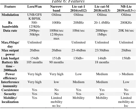
- End-products availability. Table 6: Features
Feature LoraWan Narrow-band Lte cat-1 2016(rel12) Lte cat-M 2018(rel13) NB-Lte 2019(rel13+) Modulation UNB/GFS
K/BPSK
Ofdma Ofdma Ofdma Ofdma
Rx bandwidth
500-125KHz
100Hz 20MHz 20-1.4MHz 200KHz
Data rate 290bps-50kbps
100bit/sec 12/8bytes max
10bit/sec 200kbps-1Mbps
20K bit/sec
Max.#Msgs/ day
Unlimited Unlimited Unlimited Unlimited
Max output power
20dbm 20dbm 23-46dbm 23/30dbm 20dbm
Link budget 154db 151db 130db+ 146db 150db
Battery life time -2000mah
105 months 90 months 18 months
Power efficiency
Very high Very high Low Medium > Medium
Interference immunity
Very high low Medium Medium Low
Coexistence Yes No Yes Yes No
Security Yes No Yes yes Yes
Mobility/ localization
Yes Limited mobility no loc
Mobility Mobility Limited mobility no
- Strength of the ecosystem to confirm quality and permanency of the solution.
The state of LoRa and LoRaWAN in other regions
There are strategies for nationwide deployment, local applications, and trials in some other countries.
LoRaWAN in the US:
There are two markets in the US to test the LoRaWAN IoT networks (Philadelphia and San Francisco). They have been designated for trials in IoT applications such as asset tracking, utility metering, and environmental monitoring.
However, Senet presents the first public LPWAN for IoT applications, using LoRaWAN in North America with coverage in more than 100 US cities.
LoRaWAN in Oceania:
On 20th September 2014, Semtech is deploying a LoRaWAN -based network in New Zealand, promising to cover half the population.
Focus on Asia-Pacific:
Several creativities are being deployed in Asia on top of Australia and New Zealand and Semtech and others are commonly present at events in the region.
To deploy a LPWAN network using the LoRaWAN protocol in its current fiscal year Telecom Asia covered the plans of Japanese operator SoftBank.
In India, Tata Communications promised at the end of 2015 that it would deploy a LoRaWAN network, which had been tried in Mumbai, Delhi and Bangalore. And on July 12th, Semtech released a statement saying that the national deployment of a LoRaWAN IoT network in South Korea by local telecom provider SK Telecom covered 99 percent of the population.
7. LORAWAN SIMULATION
This section discusses the design methodology and overviews the block sets in blocks include. [9]
7.1 Block Sets
Fig. 8. The proposed simulation model.
Figure 8 shows a general view of the blocks used for the simulation model of Lora Transceiver using Matlab Simulink for the following fundamental components.
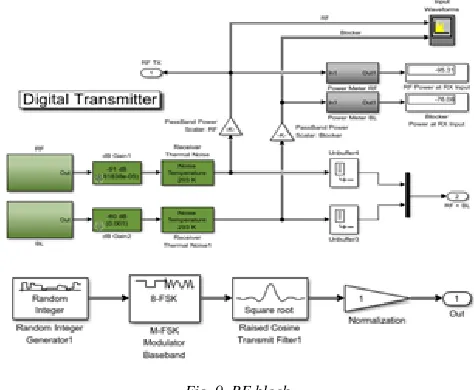
Digital Transmitter:
Figure 9 shows the digital transmitter including two 8-PSK modulated waveforms, a target waveform, and an interfering waveform. For pass band-waveform power measurement and spectrum visualization, the waveforms are scaled by 1/√2 and spaced in frequency.
RF-Blockset:
Figure 10 shows the RF Block set consisting of amplifiers, mixers, S-parameter blocks, and other blocks for designing architectures for wireless transmitters and receivers in communications and radar systems. It permits to simulate RF amplifiers to guess gain, noise, even-order, and odd-order intermodulation distortion. Mixers are used to guess image rejection, reciprocal mixing, local oscillator phase offsets, and DC conversion. Also, the paper simulates frequency-dependent impedance unequal between linear and nonlinear components in the time and frequency domains.
Fig. 9. RF block
To confirm performance and automatically set up a multicarrier simulation, the RF Budget Analyzer application permits to generate transceiver models and measurement exam benches.
Table 7: Values of low noise amplifier used in this simulation.
LNA power gain 18 db
LNA noise figure 3 db
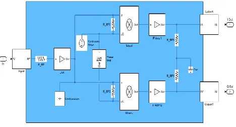
Fig. 10. RF-block set
A frequency conversion phase and two gain phases are included in the direct-conversion RF receiver. Each of the blocks capture RF impairments related to this design and each of the nonlinear blocks is specified in figure 10.
RF-Blockset basic components
The in port block imports Simulink signals into the RF Blockset. Complex-valued input signals Ik(t) + j · Qk(t) are the modulations at the frequencies {fk} stated in the Carrier frequencies parameter of the block. The Source type parameter defines the Simulink signal as either current, voltage, or power source. The Continuous wave block models a constant modulation on a carrier in the RF Blockset.
The Resistor block models a resistor within the RF Block set model input and output resistance of the RF system in addition to the isolation between the LO and RF ports of the mixers. The Amplifier block is used to model a linear or nonlinear amplifier, with or without noise. Specifying the amplifier gain using a data source also specifies input data visualization and modeling.
Low-noise amplifier (LNA) is an electronic amplifier that enlarges a very low-power signal without considerably degrading its signal-to-noise ratio. An amplifier increases the power of both the signal and the noise present at its input. LNAs are designed to decrease extra noise. The LNA non-linearity is specified by IP3 and the nonlinearity of the IF amplifiers are specified by both IP2 and IP3 parameter.
The Configuration block is used to set the model settings for a circuit envelope simulation. To distinguish each topologically distinct RF Blockset subsystem, the block parameters describe a set of simulation frequencies, solver attributes, and thermal noise. To model a thermal noise floor in the RF Blockset environment; the temperature parameter in the configuration block defines a noise temperature of 290.0 K, each configuration block specifies the parameters of the linked RF Blockset subsystem.
The Mixer block performs signal frequency translation and nonlinear amplification. For a given RF input signal and an LO input signal, the mixer multiplies the signals at the input ports, this mixing converts the frequency of RF
signal to ωRF + ωLO and ωRF – ωLO. The frequencies must be included in the simulation frequencies of the configuration block calculations for the mixer to achieve this operation correctly.
The mixer block performs amplification after mixing the RF and LO signals. The mixer scales the signals by the coefficient a1 to model linear amplification. Nonlinear amplification is implemented by a Voltage Controlled Voltage Source (VCVS) defined with a polynomial which includes saturation automatically and yields extra intermodulation frequencies.
The mixer nonlinearity is specified as a scalar. It is specified by 2nd order intercept point (IP2) parameter. The default value of this parameter is 90 deg. The phase shift is applied to all nonzero simulation frequencies. For zero (DC) frequency, the shift is constantly zero. The Outpost block outputs carrier modulation signals in the RF Block set into Simulink. RF Block set current and voltage signals consist of in-phase (Ik) and quadrature (Qk) components at each frequency fk specified in the Configuration block.
ADC Block
The ADC is modeled using an ideal sampler and an 8-bit quantizer which takes into account the full-scale range of the ADC and the dynamic range. Next, the ADC properly models the system quantization noise floor and has a direct impact on the receiver performance. The ADC block outputs digital values representing the analog input signal [9].
Fig.11. ADC Block set
Quantizer
output is calculated using the round-to-nearest method, which yields an output that is symmetric about zero.
Sampler
The sampler block holds its input for the specified sample period. The block accepts one input and generates one output. Each signal can be in scalar or vector form. If the input is a vector, the block holds all elements of the vector for the same sample period.
Limit
Saturation creates a default saturation nonlinearity estimator object for estimating Hammerstein-Wiener models.
DC Offset Cancellation
The DC Blocker block removes the DC component of the input signal. To visualize the DC offset outcome associated with RF-LO isolation the manual switch in the design allows the user to switch the offset correction subsystem in and out.
Digital receiver
As shown in Figure 12, a coordinated filter applied to the received waveform implements an AGC function and demodulate the waveform for symbol-error-rate calculation [9].
Fig. 12. Digital receiver.
The automatic gain controller (AGC):
Block adaptively adjusts its gain to achieve a constant signal level at the output.
The Discrete-Time Scatter:
Plot Scope block displays scatter plots of a modulated signal, to reveal the modulation characteristics, such as pulse shaping or channel distortions of the signal.
M-FSK Demodulator Baseband:
Using the ary frequency shift keying method, the M-FSK Demodulator Baseband block demodulates the signal. A baseband of the modulated signal is the input. The input and output for this block are discrete-time signals. This block receives a scalar value or column vector input signal of type single or double.
The M-ary number parameter (M), is the number of frequencies in the modulated signal.
8. RESULTS
As shown in Figure 13, the wave inputs, which are composed of the radio frequency (RF) and blocker, the blue wave is blocker, and the yellow wave is radio frequency. Resolution Bandwidth is 23.46kHz and it takes time 960 sec and the waveform at transmitter is the same.
Fig.13. RF + BL signal.
Figure 14 and Figure 15 show that the receiver signal is like a transmitter signal with a slight difference. This is normal due to a noise which occurs when the signal is sent, ADC has a direct influence on the receiver performance. Resolution Bandwidth at transmitter is 23.43kHz. Resolution Bandwidth at receiver is 23.44kHz. It take time 960 sec. The error rate calculation equal 0.8767.
Fig. 15. Received signal.
Figure 16 represents a constellation chart of the input signals and the relationship between Quadrature Amplitude on y-axis and In-phase Amplitude on x-axis.
Fig. 16. Discrete time-scatter
Figure 17 shows the Discrete time-scatter relation between Quadrature Amplitude and trajectory on y-axis and In-phase Amplitude on x-axis
Fig. 17. Discrete time-scatter.
9. COMPARSON
9.1 LoraWAN vs. LoraWAN Standard
In this section, we will compare the simulation of LoRaWAN with the standard of LoRaWAN. We will compare power and bandwidth because frequency band depends on the different regions, range is fixed and packet size is defined by the user [11].
End node transmit power:
Power in the standard of LoRaWAN in Europe is less than+14dBm. Power in our simulation of LoRaWAN is +14dBm.
Bandwidth:
As we mentioned previously Bandwidth= 23.44 kHz. In standard of LoRaWAN channel width= 8 x 125kHz. So, Bandwidth is less than the channel width. Which shows us that the signal can be transmitted from channel width.
9.2 LoRaWan vs other networks
Various wireless communication technologies designed at low power have been proposed and installed. Their fall within two types:
1.Local area networks which have low power with lower than 1000-m range. It contains IEEE 802.15.4, IEEE P802.1ah, Bluetooth/LE, etc., which are valid directly in short-range personal area networks. 2.Wide area networks which have low power with
greater than 1000-m range. These are low-power cellular networks, with each “cell” covering thousands of end-devices. It includes LoRaWAN, LTE Cat M, Sigfox, DASH7, etc. [11]. The differences between LoRaWAN and LTE Cat M are related to network topology and coverage, communication performance, industry standards, and security.
LoRa Alliance™ provides certification for vendor interoperability for LoRaWAN. LoRaWAN is used in low power devices with rare data transmissions and typically placed out in a star topology with gateways depending messages between end-devices and a central network server.
LTE Cat M is expected to be used for low power and infrequent data transmission devices and a mobile technology description by the 3GPP standards body. It can operate in the GSM spectrum or use an unused resource block within a LTE carrier’s guard-band.
Network Topology and Coverage
Topology:
LoRaWAN and LTE Cat M networks are connected via a tower or star-based topology and Commonly used in cellular networks, a star topology uses gateways (cellular towers).Coverage:
LoraWan:2-5k (urban), 15k (rural) LTE CAT M :2.5- 5km
Communication Performance:
Communication performance of a technology have large effect on the usable period and network functionality. LoRaWAN and LTE Cat M are designed for low bandwidth and infrequent communication. They can drive down device costs and extend battery life. Table X shows a comparison of LoraWAN versus LTE CAT M.
Bandwidth:
LoRaWAN: ~100kps LTE CAT M: ~200kps
Frequency band:
LoRaWAN: 433/868/780/915 MHz ISM LTE CAT M: Cellular
Channel width:
LoRaWAN;EU: 8x125kHz, US 64x125kHz/8x125kHz LTE cat M:1.4MHz
Packet size:
LoRaWAN: Defined by User LTE CAT M: ~100 -~1000 bytes End Node Transmit Power
LoRaWAN: EU:<+14dBm, US:<+27dBm LTE CAT M: 100 mW.
Industry Standards
Proprietary technology held by Semtech resulted in LoRaWAN. LoRaWAN is not an open standard and the use of chips made by Semtech or their licensees is needed for implementing LoRaWAN-based solutions. 3GPP is the basis of LTE Cat M, Release 13. Specific features for use in public emergencies are included in Release 13 [11]. Security
Compromised devices can be used to support attacks on other networks. So, Security is essential for any network. Compromised devices result in costly technology substitutions, or even worse, disrupt vital services or public safety [11].
Table 10 : Comparison of LoraWAN vs. LTE CAT M [10]
Standard Name LoRaWAN LTE CAT M Frequency Band ISM (433/868/780/915) MHz Cellular Width of Channel For Europe: (8x125)kHz,
For US
(64x125)kHz/(8x125)kHz
1.4MHz Range For Urban (2-5)k, For rural is
15k
(2.5- 5)km Transmit Power for
End Node
Europe:<+14dBm, US:<+27dBm 100 mW Size of Packet User define ~100 -~1000
bytes typical Data Rate for
Uplink
EU: 300 bps to 50 kbps, US:900-100kbps
~200kbps Data Rate for
Downlink
EU: 300 bps to 50 kbps, US:900-100kbps
~200kbps Devices per Access
Point
Uplink:>1M, Downlink:<100k 20k+ Topology Star on Star Star Roaming allowed
for End node
Yes Yes
Governing Body LoRa Alliance 3GPP Status In deployment Release 13
Expected 2016
Table 9: Security element of LoRaWan and LTE CAT M
Security Elements Network
LoRaWAN LTE Cat M
Authentication Chain of Trust across the platform for mutual
authentication and
applications
Not Specified Challenge/response authentication using pre-shared secret
Key Exchange and
Distribution
Static key exchange; no rotation
Key Generation and Storage Not specified
Data Transmission AES, CMAC and
pre-shared secret
LTE data transmission encryption: AES
Network Access Control Authentication via
pre-shared secret
10. CONCLUSION
The paper discussed an overview of LoRaWAN, its architecture, how it works, implementation, challenges and obstacles, market status and the design methodology of the main block sets used in LoRaWAN transceiver. LoRa Transceiver model was built with Matlab Simulink using fundamental components in Simulink to demonstrate how reliable complex modulation schemes can be built. The paper compared the simulation of LoRaWAN with the standard of LoRaWAN. We compare power and bandwidth because frequency band depend on the different regions, range is fixed, and packet size defined by the user. Comparison between LoRaWAN and LTE Cat M according to the network topology and coverage, communication performance, industry standards, and security is done.
REFERENCES
[1] Usman Raza and others, Low Power Wide Area
Networks: An Overview, Cornell university library,11 Jan 2017
[2] RASMUS HENRIKSSON, Indoor positioning in
LoRaWAN networks, Chalmers University of
Technology Göteborg, Sweden 2016
[3] MODELLING OF LORA TRANSCEIVER IN
MATLAB USING SIMULINK
[4] R. Narayan, "All You Need to Know About LoRaWAN and How It Works", IoTLeague.com, November 11, 2015
[5] LoRa Alliance, LoRaWAN What is it? Lora Alliance and Semtech, June 2016
[6] B. Ray, "WHAT IS LORAWAN? Link Labs", October 08, 2015.
[7] Technical Marketing Workgroup, "LoraWAN What is it? A technical overview of LoRa and LoRaWAN", Lora-alliance, November 2015.
[8] Haystack Technologies, LoRaWAN vs Haystack, Slide Share, Dec 12, 2016.
[9] http://in.mathworks.com/help/simrf/examples/executabl e-specification-of-a-direct-conversion-receiver.html
[10] Hardy Schmidbauer, NB-IoT vs LoRa-Technology
Which could take gold? Lora Alliance, September-2016 [11] Ferran Adelantado and others, Understanding the limits