© 2017 IJSRSET | Volume 3 | Issue 8 | Print ISSN: 2395-1990 | Online ISSN : 2394-4099 Themed Section : Engineering and Technology
Review-A Controller of Brushless DC Motor for Electric
Vehicle
Manali P. Chavhan
Faculty Member Department of Electrical Engineering Jhulelal Institute of Technology, Nagpur, India
ABSTRACT
People pay more attention to less polluting vehicles with the development of environmental protection awareness. Storage battery and electromotor are consisting in the dynamical system of an electrical vehicle. AC motor, DC motor and reluctance motor are usually used in the electric vehicle. The Brushless DC Motor has high efficiency and good performance of timing as compared to other motors. The controller has low cost and preferable stability. This paper presents a review in literature of various topologies used in Electric Vehicle as well as analyses flux weakening control in high speed and method of energy regenerative braking when the vehicle is decelerating.
Keywords: Brushless DC Motor, Electric vehicle, Flux Weakening control, Regenerative Braking.
I.
INTRODUCTION
Electric vehicle have some advantages over internal combustion engine automobiles, including a significant reduction of air pollution, reduced gas emissions, and reducing energy dependence on reducing oil reserves. Electricity stored in the battery will use by Electric vehicle to drive the motor, and the power can be rejuvenated with electricity generation using renewable energy. The most suitable motor for electric vehicle among various electric motors is BLDC motor, because this motor have high reliability, high power density, high efficiency, low cost, lower weight and low maintenance requirements.
(A)Petrol Vehicle
(B) Electric Vehicle
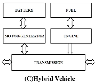
(C)Hybrid Vehicle
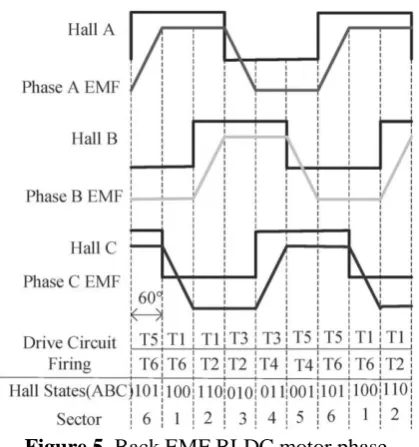
Figure 1. Block diagram of electric vehicle structure BLDC motor is normally powered by conventional three phase inverter which is controlled based on the rotor positions information obtained from Hall position sensors or simply Hall sensors. Three phase windings use one Hall Sensor each and provide three overlapping signals giving a 60° wide position range. Whenever the magnetic poles pass near the sensors, a high or low signal will produce to indicating North or South Pole is passing the pole. The controller has low cost and desirable stability. It can better perceive energy regenerative braking on an electric vehicle.
II.
MOTOR AND CONTROL
Braking System of Electric Vehicle Driven by Brushless DC Motor represented by Xiaohong Nian et.al.[01] which can improve energy usage efficiency and can prolong the driving distance of electric vehicles. The regenerative braking system is adapted to brushless dc (BLDC) motor, and it accentuates on the distribution of the braking force, as well as BLDC motor control. BLDC motor control utilizes the traditional proportional–integral–derivative (PID) control, and the distribution of braking force adopts fuzzy logic control. Because the fuzzy reasoning is slower than PID control, the braking torque can be real time controlled by PID control.
During the study of Regenerative Braking System Xiaohong Nian et.al.[01] explain Brushless DC Motor and it’s control are given below:
2.1 Brushless DC Motor
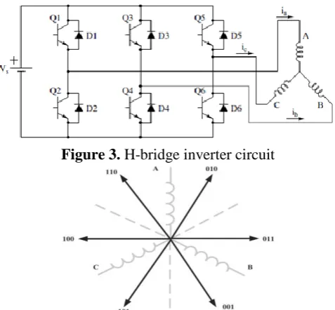
Brushless DC Motor is a type of synchronous motor. It means that the magnetic field generated by the rotor rotation and the magnetic field generated by the stator are at the same frequency. Slip is generally seen in induction motors while BLDC motor does not experience slip. However, a BLDC motor requires relatively complex electronics for control. As illustrated in Figure2, in a BLDC motor, permanent magnets are mounted on the rotor, with the armature windings being fixed on the stator with a laminated steel core. Rotation is initiated and maintained by sequentially energising opposite pairs of pole windings that are said as form phases. Knowledge of rotor position is critical to sustaining the motion of the windings correctly. The information of rotor motion is obtained either from coil EMF measurements or from Hall Effect sensors.
Figure 2. Y-connected BLDC motor construction
Figure 3. H-bridge inverter circuit
Figure 4. Six sectors of the BLDC motor voltage vector
2.2 BLDC Motor Control
Figure 5. Back EMF BLDC motor phase
III.
MATHEMATICAL MODEL OF BLDC MOTOR
Hong-xing Wu et. al. [02] presented a system based on A Controller of Brushless DC Motor for electric vehicle in which the driving system of BLDCM used in Electric Vehicle. The system has characteristics of compact structure, advantageous control, and low cost. In the control strategy, typical PI control and arithmetic of variable velocity pre-labeled value are applied. The characteristic of BLDC Motor is that the shape of counter electromotive force (EMF) is trapezium, which means that the mutual inductance between stator and rotor is nonsine. It is difficult to transform the equation of BLDC Motor to the equation of d and q axis, because the equation of d and qaxis is suitable for the motor for the motor which air gap field shape is sine. If multiparametric coordinate theory is used then the transformation is feasible. But it is very complex. Fig. 6 shows equivalent circuit diagram of BLDC Motor. Calculation error is great if the fundamental wave is transformed. By contrast, it is easy and convenient to build the mathematical model of the motor using intrinsic phase variable of motor.
Figure 6. Equivalent circuit diagram of BLDC Motor
The assumptions are as follows.
1) The stator winding is concentrative winding equispaced with 60˚. It is “Y” connection.
2) The winding is distributing on the smooth surface of stator equably.
3) The magnetic saturation is neglected. The loss of vortex and magnetic hysteresis are neglected.
4) The armature reaction is neglected and the distribution of air gap field is uniform distribution. The voltage equation of three-phase BLDCM is
i
i
i
u
u
u
c b a c b aR
R
R
0
0
0
0
0
0
+
e
e
e
i
i
i
c b a c b aP
M
L
M
L
M
L
0
0
0
0
0
0
(1)0
i
i
i
a b c (2) cc b
a Mi Mi Mi
Mi (3) Where
c b a u u
u , , - phase winding voltage of stator (Volt); c
b a i i
i , , - phase winding current of stator (Amp); c
b a e e
e , , -phase winding electromotive force of stator; L -phase winding inductance (H);
M -phase winding mutual inductance (H); P -differential operator
dt d P , So, electromagnet torque is
e
ai
ae
bi
be
ci
c
T
1
(4)
Typically, the mathematical model of a Brushless DC motor is similar to the conventional DC motor. The BLDC Motor has a permanent magnet on the rotor and three windings on the stator side. Due to the high resistivity of both magnets and stainless steel the currents induced in the rotor can be neglected.
sensitivity and influence of load torque in a permanent magnet brushless dc motor drive. Dynamic simulation results show significant reduction in the error caused by variations in parameters and load torque. On the other hand Ahmed Rubaai et. al. [04] introduced a brushless drive system with an adaptive fuzzy-neural-network controller. Using an experimental setup, the performance of the proposed controller is evaluated under various operating conditions. The controller is shown to be robust, adaptive, and capable of learning. The effectiveness of the fuzzy-neural-network controller is demonstrated by its encouraging study results, when compared with those of a proportional-integral controller.
Yilmaz Sozer et.al. [05] described direct model reference adaptive control (DMRAC) algorithm is applied to the speed control of an inverter driven permanent magnet brushless dc motor. The approximation of the nonlinear system, current limitation and the parameter changes are addressed during the development of this controller. The control is described as an outer loop speed control and an inner current loop control which has faster dynamics than the speed loop. The adaptive control is applied to the outer speed control loop. DMRAC is compared to an indirect adaptive controller and a standard PI controller. However, the DMRAC algorithm is simpler to implement. Yuan Cheng et. al. [06] presented the design principle of electric motors and drive systems for Electric Vehicles (EVs). The research work analyses the function of driving cycle, grade ability, and acceleration on EV electric motor parameters on the plots of torque speed, and provides the detailed design process and method on how to decide the rated and maximum torque and power parameters.
Comparative Study of Using Different Electric Motors in the Electric Vehicle given by Nassser Hashemnia et. al. [07]. Different types of motors are studied and compared different electric motors to see the benefits of each motor and the one that is more suitable to be used in the electric vehicle (EV) applications. There are five main electric motor types, DC, induction, permanent magnet synchronous, switched reluctance and brushless DC motors are studied. It is concluded that although the induction motors technology is more mature than others, for the EV applications the brushless DC and permanent magnet motors are more suitable than others. The use of these motors will result in less pollution, less fuel
consumption and higher power to volume ratio. The reducing prices of the permanent magnet materials and the trend of increasing efficiency in the permanent magnet and brushless DC motors make them more and more attractive for the EV applications.
Furthermore J. X. Shen et. al. [08] demonstrated the sensorless control of brushless machines by detecting the third harmonic back electromotive force is a relatively simple and potentially low-cost technique. However, its application has been reported only for brushless dc motors operating under normal commutation. Two types of AC motors that is Induction Motor and Permanent Magnet AC motor are studied by Nuno Grilo et.al. [09]. From this study they concluded that the most attractive one for a future application in electric vehicles will be a permanent magnet brushless AC motor since its configuration and dimensions are optimized.
Karen L. Butler et.al. [14] discusses a simulation and modelling package developed at Texas A&M University, V-Elph 2.01. VElph facilitates in-depth studies of electric vehicle (EV) and hybrid EV (HEV) configurations or energy management strategies through visual programming by creating components as hierarchical subsystems that can be used interchangeably as embedded systems. V-Elph is composed of detailed models of four major types of components: electric motors, internal combustion engines, batteries, and support components that can be integrated to model and simulate drive trains having all electric, series hybrid, and parallel hybrid configurations. V-Elph was written in the Matlab/Simulink graphical simulation language and is portable to most computer platforms.
R. Elavarasi et.al.[15] discusses digital pulse width modulation control implemented in FPGA for a BLDC drive in both motoring and generating modes of opera-tion with Regenerative Braking System (RBS). Regenerative braking can improve energy usage efficiency and can prolong the driving distance of Electric Vehicles (EVs). The proposed system includes BLDC motor control utilizing the traditional PID control, and the distribution of braking force adopts fuzzy logic control. RBS has the ability to recover energy and ensure the safety of braking. The implementation of digital pulse width modulation control using FPGA results in a considerable reduction of size and the cost of the system. An improved online optimal control strategy has been developed by Z.Q.Zhu et.al. [16] and applied to alternative permanent-magnet brushless ac motor topologies. The dclink current, the -axis current error, and the speed are used as optimization objectives, according to different operating scenarios. In addition, since it is coupled with feed forward vector control, based on optimal current profiles, it retains excellent transient dynamic performance, while achieving the maximum inherent power capability of the motor in the flux-weakening range and guaranteeing maximum efficiency over the entire operating range.
IV.
CONCLUSION
The Electric Vehicle is very promising and highly flexible transportation technology providing unique solution for many applications with additional features. A controller of Brushless DC Motor for electric vehicle
can be designed by using mathematical modelling of BLDC Motor. The driving system of Brushless DC motor used in Electric Vehicle is studied. The system has characteristics of compact structure, advantageous control and low cost. In the control Strategy, typical PI-control, fuzzy-neural-network system, Model Reference Adaptive Control and Direct Model Reference Adaptive Control are described in various researches. The flux-weakening control and energy regenerative braking control are the control strategies for BLDC Motor. The feasibility and high efficiency of the driving system are observed while Brushless DC motor is preferred.
V.
REFERENCES
[1]. Xiaohong Nian,Fei Peng and Hang Zhang,"Regenerative Braking System of Electric Vehicle Driven by Brushless DC Motor",IEEE Transactions on Industrial Electronics,Vol.61, No.10,October2014, pp.5798-5806.
[2]. Hong-xing Wu,Shu-kang Cheng and Shu-mai Cui,"A Controller of Brushless DC Motor for Electric Vehicle",IEEE Trans.On Magnetics, Vol.41, No.1, January 2005, pp.509-513.
[3]. P.Crnosija,Z.Ban,and R.Krishnan,"Application of model reference adaptive control with signal adaptation to PM BLDCM drives," in Proc.IEEE Int.Symp.ISIE,Vol.3,2002,pp.689-694.
[4]. A.Rubaai,D.Ricketts,and
M.D.Kankam,"Development and implementation of an adaptive fuzzy-neural-network controller for brushless drives," IEEE Trans.Ind.Appl., vol.38, no.2, Mar./Apr.2002, pp.441-447.
[5]. Yilmaz.Sozer,Howard.Kaufman and David.A.Torrey, "Direct model reference adaptive control of permanent magnet BLDCMs, " in Proc.IEEE Int.Conf.Control Applications, 1997, pp.633-638.
[6]. Yuan Cheng,Fuyi Duan,Shumei Cui,"The Design Principle of Electric Motors and Drive Systems for Electric Vehicle", Dept.Of Electrical Engg, Harbin Institute of Technology,China,pp.802-805. [7]. Nasser Hashemnia and Behzad Asaei, "Comparative Study of Using Different Electric Motors in the Electric Vehicle", in Proc.IEEE 2008 Int.Conference on Electrical Machines,pp.1-5.
EMF",IEEE Transactions on Industry Applications, Vol.40, No.6, November/December 2004, pp.1629-1636.
[9]. Nuno Grilo,Duarte M.Sousa,Antoniob Roque,"AC Motors for Application in a Commercial Electric Vehicle: designing aspects",IEEE,2012,pp.277-280.
[10]. Atef Saleh Othman Al-Mashakbeh, "Proportional Integral and Derivative Control of Brushless DC Motor", European Journal of Scientific Research,Vol.35 No.2 (2009), pp.198-203
[11]. Raju Yanamshetti,Juhi Nishat Ansari, "Microcontroller Controlled BLDC Drive for Electric Vehicle", International Journal of Engineering Research & Technology (IJERT),Vol.1 Issue 10,December- 2012,pp.1-4. [12]. K.T.Chau,C.C.Chan and Chunhua Liu,"Overview
of Permanent-Magnet Brushless Drives for Electric and Hybrid Electric Vehicles",IEEE Transaction on Industrial Electronics, Vol.55, No.6, June 2008, pp.2246-2257.
[13]. Ming Cheng,Wei Hua,Jianzhong Zhang and Wenxiang Zhao,"Overview of Stator-Permanent Magnet Brushless Machines",IEEE Transaction on Industrial Electronics,Vol.58,No.11,November 2011,pp.5087-5101.
[14]. Karen L.Butler,Mehrdad Ehsani,Preyas Kamath,"A Matlab-Based Modeling and Simulation Package for Electric and Hybrid Electric Vehicle Design",IEEE Transactions on Vehicular Technology, VOL.48,NO.6, NOVEMBER 1999, pp.1770-1778.
[15]. R.Elavarasi and P.K.Senthil Kumar,"An FPGA based Regenerative Braking System of Electric Vehicle Driven by BLDC Motor",Indian Journal of Science and Technology,Vol 7(S7),November 2014,pp.1–5.