to express its unique anisotropic properties or to fabricate a nanodevice. In this work we focused on the development of a micrometer length scale approach, based on a fluidic method for alignment and assembling of nanowires. The alignment is achieved by manipulating a droplet composed of a dilute nanowire suspension by creating thermocapillary motion inside a microchannel. Our purpose is to explore the nanowires’ alignment mechanism in the middle region between the droplet’s front and rear menisci, and their interaction with the free surface and the contact lines. Experimental results show that nanowires which are found in the middle region of the droplet are generally aligned with the flow direction. Nanowires which reach the front meniscus move together with the displacing fluid which undergoes a “rolling” type motion, and are finally adsorbed to the surface of the microchannel. The adsorbed nanowires were found in most cases to align with the droplet’s flow direction. However, in certain cases nanowires may become reoriented by the passage of the rear-contact line. © 2005 American Institute of Physics.关DOI: 10.1063/1.1925047兴
I. INTRODUCTION
Integration of nanowires共NWs兲and nanotubes into use-ful devices requires appropriate control of their alignment and assembly. This is a major challenge in the subfield of nanotechnology which follows the bottom-up fabrication paradigm.1,2 In previous works, electric3,4 and magnetic5 fields were applied to manipulate NWs suspended in a di-electric liquid medium. In general, these methods require extensive lithography to fabricate the microelectrodes. Fluidic-based methods for aligning NWs have proved suc-cessful in generating parallel and cross-bar NW assemblies.6–12 Alignment through solvent evaporation-induced self-assembly of NWs within microchannels was demonstrated by Messer et al.6NWs have also been aligned with controlled micrometer scale pitch using the Langmuir– Blodgett technique and then transferred to planar substrates in a layer-by-layer process creating large scale共over centi-meter length scales兲 hierarchical organization of NWs.7 In another work, DNA molecules suspended in water were de-posited on a substrate and subsequently oriented by the pas-sage of an air–water interface. The stretching of the DNA molecules was always perpendicular to the air–water interface.8,9 The alignment of carbon nanotubes and semi-conductor NWs embedded in polymer nanofibers was re-cently demonstrated using electrospinning.13,14 The NWs were first aligned by a sink flow, and subsequently by high extension of the electrospun jet. By manipulating the electro-static field in the electrospinning process, cross-bar structures of NWs embedded in nanofibers could be fabricated.15,16The shear response of semidilute dispersions of
polymer-dispersed multiwalled carbon nanotubes was studied by Hob-bie et al.17It is shown that for a weakly elastic polymer melt, the carbon nanotubes are oriented along the flow direction at low shear stress.
The assembly and alignment of the NWs in this work aimed at micrometer length scale assembly for applications in nanosystems. The presented approach applied a solution-based method. It is achieved by manipulating a microscale droplet composed of a dilute NW suspension within a micro-channel by means of thermocapillary motion. By this method, the NWs’ orientation could be controlled for se-quential deposition, thereby offering a flexible process for microscale pathway to microscale assembly.
The droplet motion creates several flow patterns which are responsible for the NWs’ alignment, as well as remark-able interactions between the NWs and the contact lines and between the NWs and the free surface. These interactions affect the alignment of the NWs and their adsorbance to the microchannel’s surface. Previous works have demonstrated that suspended rod-like spheroidal particles共e.g., NWs兲in a shear flow spend most of their time aligned with the stream-lines and rotate occasionally in closed orbits.18–21Hinch and Leal19 found that spheroid-shaped particles align themselves with the flow direction, assuming weak Brownian motion. The period of spheroidal particle rotation is found to be a function of its aspect ratio and of the shear rate.21,22 Szeri and Leal23,24analyzed the case of a dilute suspension of rigid rod-like particles that has a spatially inhomogeneous velocity field. Yarin et al.25extended the above works for nonaxisym-metric particles, and found that such particles may rotate in chaotic, periodic, or quasiperiodic manners. In another work, the orientation of triaxial ellipsoids in general three-dimensional共3D兲flows was investigated by Gauthier et al.26
a兲Author to whom correspondence should be addressed. Electronic mail:
using reflective anisotropic flakes to perform visualizations. They showed that the orientation of these particles indeed depends upon the shear stress of the flow. Cloitre and Mongruel27 investigated the orientation of rod-like particles in a nonuniform elongation flow at low-Reynolds number created by introducing a small orifice into a cylindrical chan-nel. They found that the orientation dynamics of a particle depends on the history of the deformation it has experienced during the flow, whereas at the orifice, all the particles were found to be fully oriented.
In this paper we report the experimental investigation of fluidic assembly of NWs. We first describe the experimental system and the procedures used to fabricate the NWs and then cause their dispersion, as well as describe the procedure employed to manipulate the droplet within the microchannel. Then, we discuss the NW alignment mechanism in different regions of the moving droplet.
II. EXPERIMENTAL DESIGN
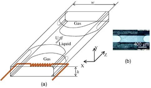
The experimental system consists of a droplet in a rect-angular microchannel. The microchannels are made from a glass pipette with a typical rectangular cross section w⫻h, where w = 400–1000m and h = 40–100m共Wale Appara-tus Co., Inc.兲 共see Figs. 1 and 2兲. The gas surrounding the droplet on both sides has a long body that touches each side of the microchannel at an apparent contact line. The gas is also supported from each corner by a meniscus which has approximately the same mean curvature as the droplet 共see Fig. 1兲. The microchannel is attached to a thermal head that was produced by a thick-layer technology and which consists of a number of resistors with a total power of 5 W. Gold NWs were produced by an electrodeposition process using templates共200 nm, length of 1–5m兲based on a proce-dure described briefly in the work of Martin et al.28,29 A representative scanning electron microscopy共SEM兲image of the gold NWs is shown in Fig. 3. In order to prevent aggre-gation of the NWs, we used surfactants such as 2-mercaptoethanol, octadecanethiol, dodecylamine, and po-tassium sulfide. The dispersion liquids were hexadecane, oc-tadecane, and silicon oil 共all were purchased from Sigma-Aldrich兲. We systematically tried combinations of the dispersion liquids with each of the surfactants to reach stable
and homogeneous suspension. The concentration of the gold NWs in the liquid media was of the order of 0.1% –0.2%共w / w兲 and the surfactant concentration was in the order of 1 %共w / w兲. The dispersions were sonicated for 10 min共using the 43 KHz Delta D2000 sonicator兲to produce a homogeneous dilute dispersion which were observed to remain stable throughout the experimental phase. The motion of the NWs was observed using an optical microscope 共Olympus BX51兲 with a magnification of 500–1000 and a video camera 共Olympus DP12, 30fps兲. The SEM micro-graphs were obtained by detecting the scattered secondary electrons using a high resolution SEM共Leo Gemini 982兲at an acceleration voltage of 2–4 kV.
III. RESULTS AND DISCUSSION
The experimental design is based on the thermocapillary motion of a droplet composed of a dilute NWs suspension inside a microchannel. The thermocapillary motion is achieved by creating a temperature gradient T1− T2 共⬃60 C兲 which results in a surface tension difference ⌬ 共⬃7 mN/ m兲 between the droplet’s front and rear menisci. Since the surface tension of the liquids used decreases as the temperature increases, the droplet moves towards the colder region.30,31
[image:2.612.318.557.49.231.2]At steady state condition we observed three types of FIG. 1.共Color online兲.共a兲A typical scheme of a droplet which is heated up
and moved by thermocapillary motion inside a rectangular microchannel 共w⫻h兲,共b兲a top view photo of a liquid droplet inside the microchannel.
FIG. 2.共Color online兲. Schematic illustration of a droplet in a microchannel. 共a兲A cross-sectional view.共b兲A top view. Three types of flow regions are presented:共I兲A Poiseuille flow,共II兲a “rolling” type motion, and 共III兲 a sink-source-like flow.
[image:2.612.54.296.50.191.2] [image:2.612.318.557.627.730.2]flow patterns in the droplet共see Fig. 2兲:共a兲a Poiseuille flow 共region I兲, which develops due to the pressure difference between the droplet’s rear and front menisci, P1− P2
⬃⌬/ R, where R⬃h / 2 is the radius curvature of the droplet meniscus;共b兲a rolling type motion near the menisci regions 共region II兲 共Refs. 32 and 33兲; and共c兲a sink/source-like flow at the interface of the menisci and the microchannel’s cor-ners, where the spreading of the liquid occurs共region III兲.
Within region I, since wⰇh, the flow can be considered as a two-dimensional flow关see Fig. 2共a兲兴. The effect of ro-tational Brownian motion is excluded in this work, due to the size of the nanowires which are already too big and, at the same time, small enough to allow us to neglect both their mass and inertial moment. We assume that the influence of the dynamic contact lines on this region is negligible.34 The determined mean velocity of the droplet is U = R⌬/ 3L ⬃1 mm/ s, where L is the droplet length andis the viscos-ity of the fluid. The determined velocviscos-ity is in a good agree-ment with the measured mean velocity U⬃0.5–1 mm/ s. Consequently, the typical average shear rate of the flow is
␥= 10 s−1, where the capillary and Reynolds numbers in this
flow are Ca=U /⬃10−3 and R
e=hU /⬃10−1–10−3,
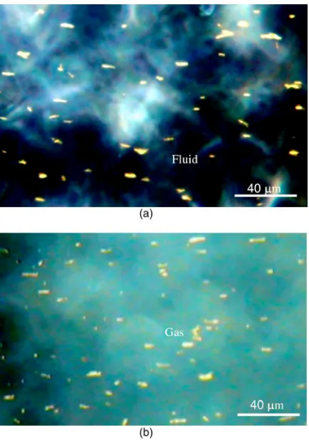
re-spectively, where is the density of the fluid. Real time observations show that most of the time the NWs were aligned with the flow, but “flip over” occasionally关see Fig. 4共a兲and movie 1, linked to Fig. 4 online兴.18,19,21The duration of the flip-over of the NWs was found to be between 1–5 s.
[image:3.612.66.283.49.358.2]In region II, we observed NWs move near the front me-niscus, turn around the corner of the contact line, and then, under certain conditions, become adsorbed to the surface. Figure 5 shows a series of pictures taken near the droplet’s front meniscus as a NW turned around the corner共see movie 2, linked to Fig. 5 online兲. At first the NW moves with a higher velocity than U until it reaches the front meniscus, at which point the NW starts “sliding” along the free surface of the meniscus. Therefore, we assume that the NW moves to-gether with the displacing fluid which undergoes a “rolling” type motion.35 In most cases, we found that the turning-around motion of the NWs near the front meniscus did not affect the alignment that was achieved within the Poiseuille flow 关e.g., see Fig. 4共b兲 for adsorbed nanowires兴 and the NWs were finally deposited with an orientation parallel to the flow direction. Observations show that over 85% of the NWs aligned with the flow direction. In general, when the NWs approach the surface of the microchannel, after the turning-around motion near the front meniscus, adhesive forces attract them to the surface and the high shear rate helps to align them. If the NWs fail to adsorb to the surface, they join the rear meniscus region and join the Poiseuille flow again further on. By this cyclic motion, increasing num-bers of NWs adhere to the surface of the microchannel关for a schematic illustration of the process see Fig. 2共a兲兴.
In certain cases, after the alignment and adsorbance of the NWs to the microchannel’s surface, reorientation may occur, caused by the passage of the droplet’s rear contact line. The NWs may adopt a specific orientation relative to the contact line. NWs aligned perpendicular to the droplet’s rear contact line are shown in Fig. 6共a兲. A series of pictures taken near the rear contact line during a NW’s rotation is shown in Fig. 6共b兲 共see movie 3, linked to Fig. 6 online兲. It shows that the NW was initially aligned with the droplet flow, but after the passage of the rear contact line, the NW was reoriented and set perpendicular to the meniscus. Figure 7 shows a NW that was at first aligned with the flow direc-tion, but during the passage of the rear contact line the NW was found to be almost tangential to the meniscus. It reori-ented itself and its final orientation was found to be about 45° relative to the flow direction共see movie 4, linked to Fig. FIG. 4.共Color online兲. A top view of region I.共a兲A view of aligned NWs
[image:3.612.347.529.50.177.2]suspended in the droplet.共b兲A view of NWs adsorbed to the microchannel’s surface. The suspension used was hexadecane/octadecane 1 : 1 with 0.2 wt%, gold NWs, and 1% 2-mercaptoethanol. The dimensions of the microchan-nel’s cross section were 1000⫻50m共enhanced online兲.
FIG. 5. 共Color online兲. A series of photos共top view兲taken near the front contact line共region II兲as the NW turning around the front meniscus. The suspension used was silicon oil with 0.2 wt%, gold NWs, and 1% potassium sulfide. The dimensions of the microchannel’s cross section were 1000
7 online兲. This situation was uncommon and it seems that the adhesion of the NW to the microchannel’s surface, or irregu-larities of the surface, prevented complete realignment. In most of the experiments we found that the reorientation due to the sweep of the rear contact line would usually fall into one or two equilibrium states:共1兲with a NW perpendicular to the contact line and 共2兲 with a NW aligned along the contact line. It appears that the first equilibrium state occurs when a NW “punches” the rear meniscus and is turned to an orientation where the moment of the surface tension forces vanishes. The second equilibrium state occurs when punch-ing does not occur and the NW stays aligned along the con-tact line. Figure 8 shows a series of pictures taken near the droplet’s front contact line. The contact line in these pictures collects the NWs once they reach its vicinity. It does so by acting as an “attractor,” seemingly due to the loose interac-tion of the NWs with the surface. In certain cases, due to NW-NW interaction, a chain of NWs is formed. NWs which cut themselves off from the contact line were found aligned with the flow direction共see movie 5, linked to Fig. 8 online兲. In region III, near the droplet’s front meniscus, the NWs were found to move along a sink-like streamline towards the
precursor liquid and were then adsorbed to the microchan-nel’s surface. A series of pictures taken near the droplet’s front contact line is presented in Fig. 9. Near the droplet’s rear contact line, the NWs were found to move along a source-like streamline flow towards region I. This sink/source flow is a result of the pressure difference be-tween the droplet and the surrounding gas, and of the Ma-rangoni stress M, which is a function of the temperature gradient, acting along the corners surfaces.36Due to the uni-form pressure at the corners, their velocity field could be assumed to be a parallel flow driven byM.
IV. SUMMARY
[image:4.612.53.293.50.163.2]In this investigation, we report on an experimental inves-tigation of a fluidic-based assembly approach. The alignment of the NWs in this work is achieved by manipulating a drop-let with a dilute NW suspension inside a microchannel by means of thermocapillary motion. Real-time observations show that the nanowires found in the middle region of the droplet共between the menisci兲were aligned most of the time with the Poiseuille flow, but they did flip over occasionally. It was observed that when NWs which were faster than the droplet’s mean velocity reached the front meniscus, they moved together with the displacing fluid which itself under-went a rolling type motion, and were finally adsorbed to the microchannel’s surface parallel to the flow direction. NWs which were found in the droplet’s middle region and had FIG. 6. 共Color online兲.共a兲A photo of the gold NWs’ alignment as they
reach the droplet’s rear contact line, with the inset showing a summary of the realignment process shown in the photo.共b兲A series of photos taken as a NW crosses the droplet’s rear contact line. The suspension used was hexadecane/octadecane 1 : 1 with 0.2 wt%, gold NWs, and 1% octade-canethiol. The dimensions of the microchannel’s cross section were 400
⫻40m共enhanced online兲.
FIG. 7.共Color online兲. A series of photos taken near the rear contact line as a nanowire crosses the rear contact line. The suspension used was hexadecane/octadecane 1 : 1 with 0.2 wt%, gold NWs, and 1% octade-canethiol. The dimensions of the microchannel’s cross section were 1000
[image:4.612.348.528.51.196.2]⫻50m.共The white spots seen in the gas phase are caused by the scatter-ing of light by NWs adsorbed to the microchannel surface and are probably coated with a thin film of liquid.兲 共Enhanced online.兲
FIG. 8.共Color online兲. A series of photos共top view兲taken near the droplet’s front contact line showing the “attraction” effect of the contact line. The suspension used was hexadecane/octadecane 1 : 1 with 0.2 wt%, gold NWs, and 1% octadecanethiol. The dimensions of the microchannel’s cross section were 1000⫻50m共enhanced online兲.
[image:4.612.84.266.555.681.2] [image:4.612.330.546.634.693.2]maintain the alignment achieved by the shear flow, the nanowire-surface and nanowire-liquid interactions needed to be controlled. Also, it was found that due to the rectangular cross section of the microchannel, a sink-source-like flow developed along the corners of the microchannel near the menisci. This phenomenon led to the movement of a small percentage of the NWs towards the corner regions. In sum-mary, we observed that the majority of the NWs were ad-sorbed to the microchannel’s surface with a good degree of alignment with the flow direction. Hence, with a greater the-oretical understanding of these observed alignment mecha-nisms and the selection of an appropriately patterned surface, the proposed fluid-based assembly can be used for the bottom-up assembly of nanodevices.
ACKNOWLEDGMENT
The authors thank Professor Alexander Yarin for valu-able discussions.
1
C. M. Lieber, “The incredible shrinking circuits,” Sci. Am. 285, 50 共2001兲.
2
G. M. Whitesides and B. Grzybowski, “Self-assembly at all scales,” Science 295, 2418共2002兲.
3
P. A. Smith, C. D. Nordquist, T. N. Jackson, T. S. Mayer, B. R. Martin, J. Mbindyo, and T. E. Mallouk, “Electric field-assisted assembly and align-ment of metallic nanowires,” Appl. Phys. Lett. 77, 1399共2000兲.
4
O. Harnack, C. Pacholski, H. Weller, A. Yasuda, and J. M. Wessels, “Rec-tifying behavior of electrically aligned ZnO nanorods,” Nano Lett. 3, 1097共2003兲.
5
M. Tanase, L. A. Bauer, A. Hultgren, D. M. Silevitch, L. Sun, D. H. Reich, P. C. Searson, and G. J. Meyer, “Magnetic alignment of fluorescent nano-wires,” Nano Lett. 1, 155共2001兲
6
B. Messer, J. H. Song, and P. Yang, “Microchannel networks for nanowire patterning,” J. Am. Chem. Soc. 122, 10232共2000兲.
7
D. Whang, S. Jin, Y. Wu, and C. M. Lieber, “Large-scale hierarchical organization of nanowire arrays for integrated nanosystems,” Nano Lett.
3, 1255共2003兲.
8
C. A. P. Petit and J. D. Carback, “Combining of molecules in microchan-nels共COMMIC兲: A method for micropatterning and orienting stretched molecules of DNA on a surface,” Nano Lett. 3, 1141共2003兲.
9
L. J. Gau, X. Cheng, and C.-F. Chou, “Fabrication of size-controllable nanofluidic channels by nanoimprinting and its application for DNA stretching,” Nano Lett. 4, 69共2004兲.
10
Z. Deng and C. Mao, “DNA-templated fabrication of 1-D parallel and 2-D crossed metallic nanowire arrays,” Nano Lett. 3, 1545共2003兲.
11
Y. Huang, X. Duan, Q. Wei, and C. M. Lieber, “Directed assembly of one dimensional nanostructures into functional networks,” Science 291, 630 共2001兲.
12
W. Salalha and E. Zussman, “Nanowires assembly using microfluidics: An experimental investigation,” in Proceedings of the 21st International
E. Zussman, A. Theron, and A. L. Yarin, “Electrostatic field-assisted building 3-D nanostructures from electrospun nanofibers,” Appl. Phys. Lett. 82, 973共2003兲.
17
E. K. Hobbie, H. Wang, H. Kim, S. Lin-Gibson, and E. A. Grulke, “Ori-entation of carbon nanotubes in a sheared polymer melt,” Phys. Fluids 15, 1196共2003兲.
18
C. Petrie, “The rheology of fiber suspensions,” J. Non-Newtonian Fluid Mech. 87, 369共1999兲.
19
E. J. Hinch and L. G. Leal, “The effect of Brownian motion on the rheo-logical properties of a suspension of non-spherical particles,” J. Fluid Mech. 52, 683共1972兲.
20
H. L. Goldsmith and S. G. Mason, “The micro-rheology of dispersions,” in Rheology, edited by F. R. Eirich共Academic, New York, 1967兲, Vol. 4, pp. 85–260.
21
D. L. Koch and E. G. Shaqfeh, “The average rotation rate of a fiber in the linear flow of a semidilute suspension,” Phys. Fluids A 2, 2093共1990兲.
22
G. B. Jeffery, “The motion of ellipsoidal particles immersed in a viscous fluid,” Proc. R. Soc. London, Ser. A 102, 161共1922兲.
23
A. J. Szeri and L. G. Leal, “A new computational method for the solution of flow problems of microstructured fluids part 1. Theory,” J. Fluid Mech.
242, 549共1992兲.
24
A. J. Szeri and L. G. Leal, “A new computational method for the solution of flow problems of microstructured fluids part 2. Inhomogeneous shear flow of a suspension,” J. Fluid Mech. 262, 171共1994兲.
25
A. L. Yarin, O. Gottleib, and I. V. Roisman, “Chaotic rotation of triaxial ellipsoids in simple shear flow,” J. Fluid Mech. 340, 83共1997兲.
26
G. Gauthier, P. Gondret, and M. Rabaud, “Motion of anisotropic particles: Application to visualization of three-dimensional flows,” Phys. Fluids 10, 2147共1998兲.
27
M. Cloitre and A. Mongruel, “Dynamics of non-Brownian rodlike par-ticles in a nonuniform elongational flow,” Phys. Fluids 11, 773共1999兲.
28
B. R. Martin, D. J. Dermody, B. D. Reiss, M. M. Fang, L. A. Lyon, M. J. Natan, and T. E. Mallouk, “Orthogonal self-assembly on colloidal gold-platinum nanorods,” Adv. Mater.共Weinheim, Ger.兲 11, 1021共1999兲.
29
Our process was the following: In order to produce gold nanowires 共GNWs兲, a Whatman Anodisc membrane共No. 47兲with 200 nm diameter pores was pretreated by evaporating 3000 Å of silver on the branched side of the membrane. After being electroplated with gold for 30 min共2 V and 0.2 A兲, the alumina membrane was dissolved in KOH共6 g for 100 ml of water兲for 15 min, the silver electrode was removed by a brief immersion of the membrane in 6 M nitric acid, and the rods washed with water to remove any residual base and salts.
30
A. L. Yarin, W. Liu, and D. H. Reneker, “Motion of droplets along thin fibers with temperature gradients,” J. Appl. Phys. 91, 4751共2002兲.
31
T. S. Sammaraco and M. A. Burns, “Themocapillary pumping of discrete drops in microfabricated analysis devices,” AIChE J. 45, 350共1999兲.
32
E. B. Dussan V., “On the spreading of liquids on solid surfaces: Static and dynamic contact lines,” Annu. Rev. Fluid Mech. 11, 371共1979兲.
33
H. K. Moffatt, “Viscous and resistive eddies near a sharp corner,” J. Fluid Mech. 18, 1共1964兲.
34
S. H. Davis and L. M. Hocking, “Spreading and imbibition of a viscous liquid on a porous base. II,” Phys. Fluids 12, 1646共2000兲.
35
E. B. Dussan V., “The moving contact line: The slip boundary condition,” J. Fluid Mech. 77, 665共1976兲.
36