and outlet plena and we studied the effect of the geometry on the flow and heat transfer. The vapor-water two-phase flow patterns were observed in the parallel microchannels through a microscope and high-speed video camera. It was observed that hydraulic in-stabilities occur. Existence of a periodic annular flow was also ob-served, which consists of a symmetrically distributed liquid ring surrounding the vapor core. Along the microchannel axis, the peri-odic dry zone appears and develops. The thermal visualization and temperature measurements of the heated device were carried out using infrared thermography. As long as the flow was single phase liquid, the forced convection heat transfer resulted in a moderate irregularity on the heated chip. These temperature differences do not cause damage to a real electronic device. The steady-state heat transfer for different types of microchannels has been studied also at the range of heat flux where phase change of the working fluid from liquid to vapor took place. Under conditions of flow boiling in microchannels, a significant enhancement of heat transfer was established. In the case of uniform heat flux the hydraulic instabil-ities lead to irregularity of temperature distribution on the heated chip. In the case of nonuniform heat flux the irregularity increased drastically.
Index Terms—Flow pattern, hydrodynamic instabilities, parallel microchannels, thermal irregularity, thermal pattern.
NOMENCLATURE
Hydraulic diameter.
Heated area of the test module. Input current.
Average flow rate in the channel. Flow rate in the certain channel.
—Reynolds number.
Maximum temperature on the heated wall, corre-sponding to a given channel.
Maximum temperature of the whole heated surface. Temperature of the heated surface at given point. Mean velocity of water in microchannel. Input voltage.
Kinematic viscosity.
Ratio of heat, transferred to the working fluid, to the total heat.
Manuscript received April 30, 2000; revised November 10, 2000. This work was supported by the Fund for the Promotion of Research at the Technion, the Ministry of Absorption, State of Israel, and the Israeli Ministry of Science. This paper was recommended for publication by Associate Editor T.-Y. T. Lee upon evaluation of the reviewers’ comments.
The authors are with the Department of Mechanical Engineering, Technion—Israel Institute of Technology, Haifa, 32000 Israel (e-mail: [email protected]).
Publisher Item Identifier S 1521-3331(01)01379-4.
Hydraulic.
Number of a certain channel. Heated wall.
I. INTRODUCTION
C
OOLING of electronic equipment has gained considerable importance, as a result of the increase of power densities in micro-electronic equipment made possible by advances in semiconductor technology [1]. Although in cooling techniques the air is often used [2], but for very high heat fluxes the heat transfer in liquids flowing through microchannels become more effective.Boiling of liquids in microchannels have unique significance in the development of new technologies and devices for con-trol of energy transfer and other advanced applications requiring very compact and extremely high heat-flux. The electronic chip is able to be effectively cooled by means of flow boiling in mi-crochannels, fabricated on the circuit board on which the chips are mounted, and the dissipated heat flux could be of the order of 1000 kW/m , while the surface temperature was maintained at the level of less than 130 C. Cooling systems based on the principle of phase change (evaporation/boiling—condensation) of heat transfer medium in a closed space, are progressively re-placing the use of standard air and liquid (one-phase) coolers in the thermal control of electronic equipment. These two-phase heat transfer elements fall into two categories.
1) Passive coolers (without any forced pumping action). In these passive two-phase heat transfer sealed elements the film evaporation or pool boiling takes place in the evap-orator part. The capillary effect or the gravity is used for returning the liquid from the condenser to the evaporator. 2) Pumped liquid coolers, where a pump supplies an
evapo-rator with the liquid. Such coolers can be designed as
a) indirect coolers, when the electronic equipment is attached to the outer surface of the evaporator part (usually called cold plates);
b) immersion coolers when the electronic equipment is directly submerged in the liquid in the evap-oration part. In the present study some types of pumped liquid coolers are examined.
As reviewed and discussed by Peng and Wang [3], the heat transfer in liquids flowing through microchannels is quite dif-ferent from that for conventional-sized channels. Recently, the experimental investigation on the flow boiling of liquid flowing
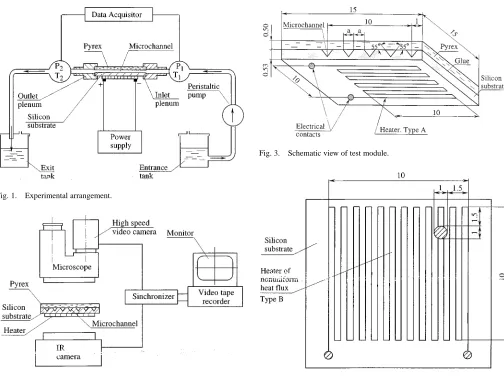
Fig. 1. Experimental arrangement.
Fig. 2. Flow and thermal visualization.
through triangular microchannels by Peng et al. [4] showed that the wall superheat for the onset of boiling is very low, and there is almost no partial nucleate boiling regime. Clusters of vapor were observed that left the channel immediately as the heated fluid flowed out of the microchannels. As a result the pressure fluctuating takes place and nonuniform heat transfer in microchannels occurs. It was reported by Peng and Wang [3] that triangular microchannels could promote more effectively the flow boiling heat transfer than rectangular microchannels.
Heat transfer of two-phase flow in a heated capillary was studied by Peles et al. [5] and a quasi-one-dimensional model of capillary flow in a heated microchannel was developed. The approach allows estimation of the effects of capillary, inertia, frictional and gravity forces on the velocity and temperature dis-tributions along a single capillary. The study of two-phase flow in parallel pipes where the feed is from a common manifold is an interesting problem as the two phases may split unevenly when entering the parallel piping. Experimental study has been per-formed by Ozawa et al. [6], [7]. Their work is on two-phase flow systems in parallel pipes of 3.1 mm in diameter. They attempted to simulate flow in boiling channels by the injection of air and water along the pipes. The conclusion is that the injection of air has a destabilizing effect on the pressure drop oscillations.
The surface of ultra large scale integrated circuits (ULSI), from which the heat should be transferred, may be heated by
Fig. 3. Schematic view of test module.
Fig. 4. Type of heater providing nonuniform heat flux.
a uniform heat flux, and more often for the majority of elec-tronic devices by a nonuniform heat flux. Even in the case of uniform heat flux the temperature of the cooled surface is not uniform. It is determined by the heat transfer coefficients along the surface and in the spanwise direction. The cause of this phe-nomenon is nonuniform distribution of working fluid inside the parallel channels. The heat sinks generally operate in a wide range of heat flux conditions, and the limit of nonuniform tem-perature distribution must be considered in the calculation of any pumped vapor cooler for electronic application. No work has been carried out in this area. This paper presents the results of our research program on heat transfer in parallel microchan-nels with emphasis on thermal control of electronic devices.
II. DESCRIPTION OF THEEXPERIMENTS
A. Experimental Apparatus
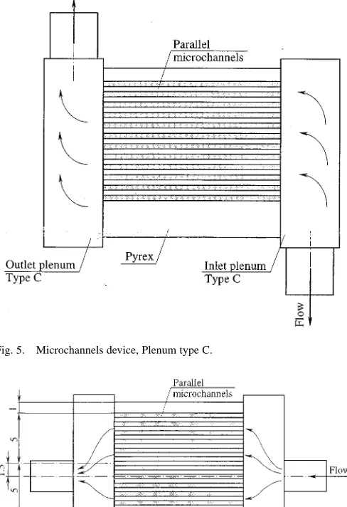
[image:2.612.288.556.62.427.2]Fig. 5. Microchannels device, Plenum type C.
Fig. 6. Microchannels device. Plenum type D.
TABLE I
GEOMETRY OFTESTMODULES
fluid was measured by 0.3 mm type T thermocouples. The pressure was measured by MPX 906 Motorola silicon pressure sensors with sensitivity 3.3 mV/kPa and response time 1.0 ms. The data were collected by Multiscan/1200 acquisition system that uses relays to provide isolation and to scan thermocouples
and volts at up to 147 channels per second. The unit can also digitize waveforms on a single channel at up to 20 kHz. The flow rate of the working fluid was controlled by adjusting the frequency of the peristaltic pump and was measured by weighing method with an accuracy of %. The entrance and the exit pressures were measured by pressure transducers with an accuracy of %, the flow temperature at the entrance and exit of the test module was measured by thermocouples with an accuracy of %. The Thermal Imaging Radiometer (IR) was used to study temperature field on the electrically heated wall (HW) simulating a computer chip from which the heat should be removed. The temperatures are determined with an accuracy of %. The input voltage and DC current were controlled by a power supply and measured with an accuracy of 0.5%.
The flow visualization technique and the visualization of the thermal field at the heated wall is shown in Fig. 2. The motion of vapor-liquid flow in the microchannels was studied using a microscope and high speed video camera with recording rate up to 10 000 fps. The playback speed can be varied from a single frame to 250 fps. The IR radiometer has a typical resolution of 256 pixels per line. With the radiometer one can obtain a quanti-tative thermal profile in the line mode, the average temperature in the area mode, and the temperature of a given point in the point mode. The frequency response of the IR is 25 frames per second. In the present study the frequency of the bubble growth in the microchannel is higher than the frequency response of infra-red radiometer, that is why we confine ourselves to mea-surements of steady state temperature field on the heated bottom of the test module.
B. Basic Design of Test Sections
the heated wall is constant. Neither heater will supply truly uni-form heat flux to the fluid, because of the concentration effects of the microchannel geometry.
In Fig. 4 (heater type B) the part of the heater, with a diam-eter of 1 mm, has the electrical resistance of less 20% than the average one. This type of heater provides nonuniform heat flux compared to the case shown in Fig. 3. The heater was connected to a DC power supply and heat generated in the heater was transferred to the liquid flow from the two sides of triangular channels. Although the channels were configurated in such a way that the cross-section of all channels would be uniform, the flow rate through each may not be equal. For the uniform heat flux case with constant flow into the channels the wall tempera-ture on the heated wall (HW) was nearly uniform. For example, when the value of the water flow velocity was equal to zero, i.e., the fluid did not move into the channels, the heated wall tem-perature varied in the range 74–76 C. For the same heat flux, temperature of the heated wall changed from 29 C to 41 C, when the water was flowing into the channels at a mean velocity
ms .
The distribution of flow rate through the channels depends on the way of connection of the test section to the inlet and outlet plena. In the present study two types of connection were studied: type C shown in Fig. 5 and type D, shown in Fig. 6. Type C provides the flow direction to the inlet plenum and from the outlet plenum that is perpendicular to the flow direction in the microchannels. Type D provides the same flow direction to the inlet and from the outlet plenum as in the microchannels. For type D to achieve significant nonuniform flow rate distribution the entrance of the flow to the inlet plenum and the exit from the outlet plenum are displaced 1.5 mm relative to the axis of the space covered by the microchannels. The geometries of the tested modules are given in Table I.
C. Data Reduction
The parameters used in the data reduction and analysis are summarized as follows.
1) Heat Flux : In the determination of the heat flux from the HW to the working fluid, the heat losses due to conduction, convection and radiation, were taken into account. The trans-ferred heat flux was defined as , where and are input current and voltage, is the heated area of the HW,
is the ratio of the heat transferred to the working fluid to the total heat generation. For each set of steady-state experimental conditions the energy balance (based on the measurements of the inlet and outlet temperatures) was performed, and the value was calculated. The current data indicated that geometric pa-rameters such as hydraulic diameter, design and material of the inlet and outlet plena have a significant influence on the heat losses.
[image:4.612.329.527.62.201.2]2) Initial Dimensionless Flow Rate Distribution : The dimensionless flow rate distribution in each channel was calculated as , where is flow rate in a channel , and is the average flow rate. The flow rate in a certain channel was obtained using the method described by Peng and Peterson [8]. In this way, the streamwise tem-perature distribution was measured on the HW at locations corresponding to the longitudinal axis of each microchannel. It
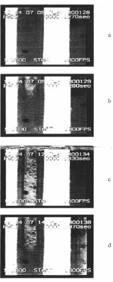
Fig. 7. Two-phase flow pattern in parallel microchannels.
Fig. 8. Periodic annular flow pattern.
[image:4.612.335.524.231.701.2]Fig. 9. Periodic rewetting and wetting of the surface.
along the microchannel in the flow direction. Correspondingly, the temperature of the HW also increases linearly in the streamwise direction. Application of this method is based on the analysis, that shows the heat transfer across the channels is significantly less than that in the direction normal to the HW. The test measurements indicated that this assumption is valid, but the longitudinal wall temperature gradient may be different due to the different flow rate . These single-phase tests are used to estimate initial dimensionless flow rate distribution, , and to calculate the maximum irregularity of initial flow rate between channels.
[image:5.612.303.555.63.223.2]Hydraulic Diameter is defined as 4 (cross section area of the microchannel)/(wetted perimeter).
Fig. 10. Thermal image of the bottom of device.
Reynolds number , where is the kinematic viscosity, is the mean flow velocity of the single phase liquid. The thermophysical properties were calculated using average temperature at the entrance and exit of the test module. The experimental conditions are given in Table II.
3) General Considerations: During the experiments, the system pressure, inlet mass flow rate and inlet water tempera-ture were kept constant. The test section was gradually heated and under certain conditions, the wall temperature and pressure drop would fluctuate with time. All of the instantaneous signals were monitored and stored on a PC, so that further statistical analysis could be done on some runs. In general, the study of two-phase phenomena starts with the formulation of the con-servation equations. At each step of formulation and solution, various physical assumptions and approximations need to be made, which have to be justified later by experiments. When the pressure drop and temperature oscillations were observed, we defined such a process as metastable region. In the present study we used time averaged flow and thermal characteristics. These characteristics, which are the steady-state solutions of the conservation equations, are also used to determine the temperature variations observed in the experiments.
Most experiments were carried out under conditions when the temperature of the heated surface varied from 70 C to 130 C. Peng and Peterson [8] studied the fluid flow and heat transfer characteristics in microchannels, and demonstrated that electronic chips could be effectively cooled by means of water flow through microchannels fabricated either directly in the sil-icon wafer or in circuit board on which the chips were mounted. The surface temperatures were maintained at a level of less than 130 C. Bar-Cohen [9] pointed out that chip temperatures must typically be maintained below 85 C.
III. RESULTS
A. Flow Visualization
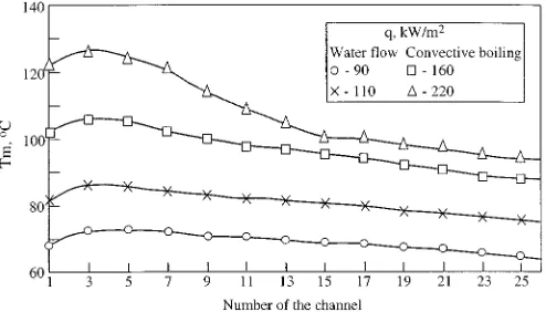
Fig. 11. Spanwise irregularity of maximum temperature on HW. Module 1. Uniform heat flux.
Fig. 12. Spanwise irregularity of maximum temperature HW. Module 2. Uniform heat flux.
or pressure drop regions, where hydrodynamic instability be-comes a possibility. A study of two-component flow in parallel channels could give the design engineering information, on how to take into account the hydrodynamic instability, and decrease temperature irregularities in electronic equipment.
Fig. 7 illustrates two-phase flow, driven by pump in mi-crochannels of test module 1. Fig. 7 is the top view and the flow pattern in the parallel microchannels is observed through transparent cover. The field of view is 6.7 mm in the streamwise direction and 8.6 mm in the spanwise direction, the flow moves from the bottom to the top, the flow rate is g/s, the heat flux is kW/m . The vapor (the white regions in Fig. 7) is generated only in part of the microchannels, further-more the vapor may be generated in different parts of a certain microchannel. In the microchannels where vapor is generated, Fig. 7, three regions could be distinguishable: region 1, located close to the inlet plenum, region 2, located downstream, and region 3 located near the outlet plenum. Fig. 8 shows in detail region 1, i.e., the unsteady flow close to the inlet plenum at kW/m , g/s. In this part of microchannel the single phase water flow was mainly observed, Fig. 8(a). An interesting phenomenon frequently happened, when the applied heat flux or wall superheat was increased, clusters of vapor appeared as a jet, penetrating the bulk of the water, Fig. 8(b). The vapor jet moved in the upstream direction, and the space that it occupies increased. In this case an unstable annular flow
Fig. 13. Spanwise irregularity of maximum temperature HW Module 2. Nonuniform heat flux.
mode was observed, Fig. 8(c). After some time the annular flow mode began to disappear, Fig. 8(d). As a result, the blocking taking place in microchannels was not observed, as usually expected, for extremely small passages. However, even when the boiling occurred at the central part of a microchannel, the vapor was accumulated also in the inlet plenum. This result agrees with previous experimental studies. As it is pointed out by Peng and Wang [4] the study of the flow boiling in triangular microchannels showed that a vapor phase took place in the inlet plenum.
[image:6.612.41.288.258.399.2]The geometry of the microchannels does impact the vapor generation (Fig. 9). The observations showed that the bubble formation mechanism is completely suppressed, region 2. In this case, only forced-convection vaporization took place, Fig. 9(a). Heat was then conducted through a thin liquid layer adjacent to the solid boundary, and evaporation took place at the interface of the liquid layer and vapor core, Fig. 9(b). At the high quality of two phase flow, the hot spots (dry-out) were observed, Fig. 9(c). The temperature of the heated wall did not increase sharply, as in the CHF case, due to the periodical nature of the process. After a certain time the microchannel was again supplied with liquid [Fig. 9(d)]. As it is clear from Fig. 9(a) to (d), the time of that process is about 0.06 s at kW/m , g/s.
In region 3 the vapor formation was more intensive. One of the conclusions of the study is the extreme brevity of the time during which the presence of single phase liquid was observed in this region.
B. Effect of the Microchannel Design on the Temperature Distribution at the Surface
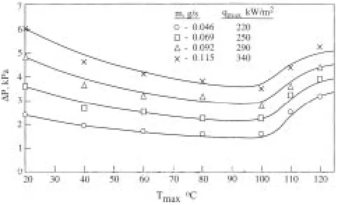
Fig. 14. Dependence of pressure drop on maximum temperature of HW.
The temperature distribution at HW depends on the mate-rial and design of the module, flow rate into the microchannels and the heat flux. For a given values of flow rate and heat flux, the infra-red (IR) image of the heated module side was clearly observed. For example, the IR image of the heated side of the module 2 is shown in Fig. 10 at g/s, kW/m . The area of the heater (marked as the square), the inlet plenum (right part in Fig. 10) and the outlet plenum (left part in Fig. 10) are also clearly distinguishable. We restricted the thermal image analysis to the marked square area of mm.
C. Effect of Heat Flux on Temperature Distribution
The results based on experimental measurements at the same entrance flow rate g/s are presented in Figs. 11–13, for test module 1, 2, and 3, respectively. The measured positions are located on the lines of the heated bottom opposite to the lines corresponded to the streamwise axis of each microchannel. These positions were determined on the back of each microchannel using special software package. For each line on the heated bottom defined in such a way, the maximum temperature was determined and in Figs. 11–13 plotted versus number of correspondent microchannel.
The measurements performed in the range of heat flux from kW/m to kW/m showed that for all the module types tested the irregularity of across the heated bottom, increases with the increase of heat flux. This effect is more profound under boiling conditions. At uniform heat flux the irregularity of exceeds 20K (Fig. 11) and 30K (Fig. 12) for the test module 1 and module 2, respectively. In the case of nonuniform heat flux, (the average value kW/m , the maximum value kW/m ) the irregularity of exceeds 60K (Fig. 13).
The temperature distribution along the flow direction for a fixed flow rate. are different for different devices. This suggests that the heat transfer mechanism in these devices is not identical. In the test module 1, it seems, that the spanwise flow rated dis-tribution is more uniform than that in test module 2. The nonuni-form (of about 20%) heat flux leads to the conditions at which the wall temperature increases sharply. Idealizing the heat flux as uniform can result in a significant error in prediction of tem-perature distribution of the heated electronic device.
maximum temperatures, making the cooling problem very chal-lenging.
In the microchannel heat sink, the large amount of heat gen-erated by the semiconductor chips may be carried out from the package by a relatively small amount of single-phase coolant, so the coolant exists at a relatively high temperature.
This undesirable temperature gradient is an important con-sideration in the design of an electronic cooling scheme. The maximum temperature difference for micro-channel system about 15–20 C may be attributed to moderate temperature irregularities [10]. A large temperature rise produces thermal stresses in chips due to the coefficient of thermal expansion mismatch among different materials thus undermining device reliability. Furthermore, a large temperature gradient is un-desirable for the electrical performance since many electrical parameters are adversely affected by a substantial temperature rise. Two-phase hydraulic instability is of great concern in the design and operation of heated channels with subcooled liquid flow, and can lead to serious safety problems. Two-phase flow instabilities are divided into dynamic and static categories. The dynamic instabilities involve transient, inertial dynamic and feedback effects. The static instabilities can be analyzed based on the pressure drop-flow rate characteristics. Two-phase microchannel heat sink could reduce these temperature vari-ations. However, a two-phase scheme has a drawback, such as hydraulic instabilities. For both single phase and two-phase microchannel heat sinks the temperature variation depends on heat flux and liquid flow rate.
Fig. 14 shows experimental results of the pressure drop as a function of the maximum device temperature for different values of initial flow rate. Note, that the maximum surface temperature, 125 C, is achieved at different values of heat flux depending on the initial flow rate. The curves demonstrate, when the improvement of the cooling is achieved by allowing phase change within the channels,
C, the pressure drop increases. The data are in good quali-tative agreement with results reported by Bowers and Mudawar [11]. They showed that the behavior of the pressure drop under conditions of flow boiling depends on the channel size. For vapor-liquid flow it is higher than that for single phase water flow.
IV. CONCLUSIONS
present experiments were performed for flow through channels fabricated in the silicon substrate, this study has been moti-vated by a number of potential applications. Microfabrication technology enables to manufacture a variety of structures and flow conduits. Microfabrication is accomplished by a combina-tion of material removal and deposicombina-tion processes. Material can be removed by various lithographic techniques such as dry and wet chemical etching, laser ablation etc. Material can be added through thin film deposition, metal plating, epitaxial growth, or bonding. Because of its good mechanical and electrical proper-ties, silicon has been the most common material used in micro-machining; but other materials, such as GaAs, glass, quartz, and ceramics, may also be used. The thermal resistance of the device depends on the thickness of the substrate and on its thermal con-ductivity. For the same thermal resistance, our results (focused on the study of transport processes in parallel microchannels made of silicon) may be applied to other materials.
As long as the flow is in single-liquid phase the forced con-vection heat transfer at moderate heat fluxes, results in a mod-erate streamwise temperature irregularity on the heated bottom. These temperature differences do not cause damage to the de-vice. The steady-state heat transfer for different types of mi-crochannel devices has been studied also at the range of heat flux where phase change of the working fluid from liquid to vapor takes place. Under conditions of flow boiling in microchannels a significant enhancement of heat transfer was established. On the other hand, the flow boiling in parallel microchannels, is ac-companied by hydraulic instabilities. Existence of two types of a periodic flow pattern was newly observed. The periodic an-nular flow is represented by a symmetrically distributed liquid ring surrounding vapor core, that appears periodically. The ex-istence of periodic dry zone involves the periodic appearance of hot spots leading to rewetting or wetting of the surface. In the case of uniform heat flux the hydraulic instabilities cause irreg-ularity of temperature distribution on the heated bottom of the device. In the case of nonuniform heat flux, the irregularity in-creases drastically. Two-phase microchannel heat sinks does not maintain both streamwise and spanwise uniformity of heat sink temperatures, when the hydraulic instabilities occur.
REFERENCES
[1] A. Bar-Cohen, “State-of-the-art and trends in the thermal packaging of electronic equipment,” J. Electron. Packag., vol. 114/257, Sept. 1992. [2] , “Optimization of vertical pin-fin heat sinks in natural convective
heat transfer,” in Proc. Heat Transfer 11th IHTC, vol. 3, Kyonju, Korea, Aug. 23–28, 1988, pp. 501–506.
[3] X. F. Peng and B. X. Wang, “Forced convection and boiling character-istics in microchannels,” in Proc. Heat Transfer 11th IHTC’98, vol. 1, Kyongiu, Korea, Aug. 23–28, 1998, pp. 371–390.
[4] X. F. Peng, H. Y. Hu, and B. X. Wang, “Boiling nucleation during liquid flow in microchannels,” Int. J. Heat Mass Transf., vol. 41, pp. 101–106, 1998.
[5] Y. P Peles, L. P. Yarin, and G. Hetsroni, “Heat transfer of two-phase flow in a heated capillary,” in Proc. Heat Transfer 11th IHTC’98, vol. 2, G. Lee, Ed., Kyongju, Korea, Aug. 23–28, 1998, pp. 193–198.
[6] M. Ozawa, K. Akagawa, and T. Sakaguchi, “Flow instabilities in par-allel-channel flow systems of gas-liquid two-phase mixtures,” Int. J.
Multiphase Flow, vol. 15, pp. 639–657, 1989.
[7] M. Ozawa, K. Akagawa, T. Sakaguchi, T. Tsukahara, and T. Fujii, “Os-cillatory flow instabilities in air-water two-phase flow systems—1st re-port, pressure drop oscillation,” Bull. JSME, vol. 22, pp. 1763–1770, 1979.
[8] X. F. Peng and G. P. Peterson, “Convective heat transfer and flow friction for water flow in microchannel structures,” Int. J. Heat Mass Transf., vol. 39, pp. 2599–2608, 1996.
[9] A. Bar-Cohen, “Thermal management of electric components with di-electric liquids,” in Proc. ASME/JSME Thermal Eng. Joint Conf., vol. 2, J. R. Lloyd and Y. Kurosaki, Eds., 1996, pp. 15–39.
[10] K. Vafai and L. Zhu, “Analysis of two-layered micro-channel heat sink concept in electronic cooling,” Int. J. Heat Mass Transf., vol. 42, pp. 2287–2297, 1999.
[11] M. B. Bowers and I. Mudawar, “High flux boiling in low flow rate, low pressure drop mini channel and micro-channel heat sinks,” Int. J. Heat
Mass Transf., vol. 37, pp. 321–322, 1994.
Gad Hetsroni is Danciger Professor of Engineering at the Technion—Israel Institute of Technology, Haifa. He has occupied positions at Westinghouse, EPRI, and Stanford University, Stanford, CA. He has also served as Director of the National Council for Research and Development in Israel, and as Dean of the Faculty of Mechanical Engineering at the Technion. He has worked on many different aspects of two-phase flow and is the founder and Editor of the International Journal of Multiphase Flow and the Editor of the Handbook of Multiphase Systems. Dr. Hetsroni is a Fellow of the ASME International, was Vice President, Re-gion 13, and is a Governor of ASME International.
Albert Mosyak received the Ph.D. degree from the Technological Institute, Odessa, Ukraine, in 1972.
He is with the Technion—Israel Institute of Technology, Haifa. He has worked in the field of heat transfer, including two-phase flow and heat transfer in microchannels.
Zelik Segal received the Ph.D. degree from the Water Transport Institute, St. Petersburg, Russia, in 1966.