THERMODYNAMICS ANALYSIS OF RECOVERING HEAT FOR
REFRIGERATION SYSTEM OF A FISHING VESSEL
R. Poku
1,* and E. A. Ogbonnaya
21,2
D
EPT.
OFM
ARINE/M
ECHANICALE
NGR.,
N
IGERD
ELTAU
NIV.,
W
ILBERFORCEI
SLAND,
B
AYELSAS
TATE,
NIGERIA
E-mail addresses:
1[email protected],
2[email protected]ABSTRACT
With the huge quantum of energy that is often wasted from the diesel engine exhaust of a typical fishing vessel, this research was conducted. It focuses on the potential of harnessing the exhaust heat from the engine in vapour absorption refrigeration system (VARS) of the vessel. The VARS considered here employs ammonia as refrigerant with water as the absorbent which are environmentally-friendly. The system was considered integral to a diesel engine which provides the heat energy needed. The system was analyzed theoretically by calculating the performance using thermodynamics analysis developed and applied to the various components of the VARS. The results show that with 349.69 kW heat energy from the exhaust gas, 314.50 kW accounting for about 90 % was utilized to vapourize the ammonia from its solution. Also, with a generator temperature of 1300C the coefficient of performance (COP) was obtained as 29.67 % which is low when compared to the COPs of vapour compression refrigeration system (VCRS). However, the work shows that the twin benefits of environmental pollution reduction as well as waste energy utilization were achieved.
Keywords: Diesel Engine, Heat Energy, VARS, Refrigerant, VCRS, COP
Nomenclature
VARS = Vapour absorption refrigeration system VCRS = Vapour compression refrigeration system COP = Coefficient of performance
= Energy from exhaust gases (kJ). = Heat liberated in fish cooling (kJ). = Total heat liberated by fish (kJ).
Oinput = Heat supplied by combustion of fuel (kJ),
= Heat gain through walls, floor and ceiling (kJ). (kJ).
= Internal load (kJ).
= Heat given off by the fish in freezing (kJ). = Heat of fish in cooling from freezing to storage
space temperature (kJ).
= Heat loss to the surrounding through radiation. = Heat removed through engine coolants (kJ). (kJ)
̇ = Total surface area of Storage space (m2).
= Temperature difference of storage space (0C). = Concentration of the weak ammonia solution. = Concentration of strong ammonia solution.
1. INTRODUCTION
Refrigeration plays a vital part in the preservation of perishable cargoes and provisions for the crew onboard vessels. In merchant vessels, the temperature of victuals and cargoes such as food, chemicals, liquefied gas etc. are controlled by the refrigeration plant of the ship. The main purpose of ship refrigeration plant is to prevent loss of the cargoes or perishables so as to ensure their safe transportation in good and healthy condition [1].
Refrigeration is the science of producing and maintaining temperature of a particular space below that of the surrounding atmosphere [2]. This implies the expulsion of heat from a substance to be cooled. Heat transfer therefore, occurs progressively from a warm body to a cooler one until both bodies are at equal temperatures. A typical refrigeration cycle transfers thermal energy from a low temperature region to a region of higher temperature. The higher temperature region is called a sink and is usually the ambient air or cooling water [3].
The most common types of refrigeration systems are the vapour compression refrigeration system (VCRS) and the vapour absorption refrigeration system (VARS). Both VCRS and VARS have the evaporator,
Vol. 37, No. 4, October 2018, pp.
936 – 944
Copyright© Faculty of Engineering, University of Nigeria, Nsukka,condenser and expansion or throttle valve as common components. However, besides these components, the VARS has the generator, absorber, pump and heat exchangers that replace the compressor in the VCRS. In the evaporator, the working fluid absorbs heat from the cold body. The heat absorbed is used as latent heat for converting the working fluid from liquid state to vapour state. During condensation, the working fluid rejects heat to external body (surrounding), thus creating a cooling effect in the working fluid. Rectifier otherwise known as drier plays an important role in the refrigeration systems [4]. Contained in the rectifier is a desiccant whose function is to completely remove or dry out moisture in refrigerants. It also helps in filtering out particles to prevent it from circulating through the system.
The VARS makes use of heat energy generated from solar panel, steam or radiator heat and temperature of exhaust gas to vapourize the working fluid. It utilizes cooling fluid (refrigerant) which is absorbed on exiting the evaporator; the absorbent is usually a solid or liquid. To achieve a continuous process, the refrigerant needs to be separated from the absorbent and subsequently condensed for a simple absorption system. Lithium bromide (absorbent) and water (refrigerant); water (absorber) and ammonia (refrigerant) are the common pairs widely used in industry [5] as refrigerants-absorbent pairs for VARS [6].
VARS based on the ammonia water pair as refrigerants are more versatile than systems based on the lithium-bromide pair [7]. In ammonia water absorption system, ammonia vapour leaving the evaporator is readily absorbed in the low temperature hot solution in the absorber. This process is accompanied by the rejection of heat. The ammonia in water solution is pumped to the higher pressure and is heated in the generator. Heat in the form of either engine exhaust gas, solar heat or any other heat source [8] is directed to the generator containing solution of ammonia water solution, rich in ammonia. The heat causes high pressure ammonia vapour to desorb from the solution and passes to the condenser. The weak ammonia in water solution remaining is then returned to the absorber.
Applications of VARS and refrigerants had evolved through the years. Ahmed [9] accordingly, opined that in 1859 an absorption system was used by a man named Ferdinand Carre with ammonia as refrigerant and water as absorbent. In 1890, Compression Refrigeration and Absorption Refrigeration became really popular [8]. Rajput [2] and Poku [6] highlighted that the type of energy supplied to the VCRS is a high grade mechanical energy which is made available by
the compressor. Whereas, for VARS the energy supplied is a low grade energy which is mainly heat and therefore, environmental pollution is also mitigated since the heat is derived from exhaust gas. According to Attishey [10]; Sohail and Tiwari [11] for the VARS, moving parts are only in the pump, which is a small element of the system. Hence, operation is smooth while in the case of the VCRS, moving parts are in the compressor therefore, more wear, tear and noise. Contemporary studies and applications of VARS also abound. Poku [6] studied the viability of VARS employing water-lithium Bromide (LiBr-H2O) as
refrigerant-absorbent pair. Recovered waste heat from the exhaust gas of a diesel engine was used as the heat source. The study showed that with exhaust gas temperature of 850C, Coefficient of Performance (COP)
of 0.85 is feasible. The air conditioning system of an automobile with the application of waste heat from the engine was investigated by Maurya et al. [12]. In this system, as an alternative power from the engine shaft as the input power to drive the compressor of the refrigeration system, waste heat from the vehicle is employed to produce the refrigeration effect. The benefit is, the engine does not need to produce extra work to run the compressor of the refrigerating system, hence saving fuel consumption.
Poku et al. [13] employed the cooling effect of VARS to achieve higher performance of a simple gas turbine cycle. In their study, VARS was applied to cool the ambient air that goes into the gas turbine plant. The study showed that gas turbine efficiency could be made to increase from 24.56% to 25.34% with inlet air cooling using VARS. Thakre et al. [14] investigated the application of VARS for the air-conditioning system of a truck cabin using the waste heat from the truck exhaust. The study showed that with exhaust temperature of 1500C, COP of 0.367% is achievable. It
also demonstrated that the power required to run the cooling system is far less. Also, since the refrigerant was of the water-ammonia pair, VARS is environmentally friendly compared to VCRS.
Pathania and Mahto [15] explored the possibility of waste heat recovery and its subsequent utilization in air conditioning system of a vehicle without increasing the component cost, weight, number of component. Bajpai [16] designed a VARS using solar energy as the heat source and using water-ammonia pair as the working fluid. The work was able to achieve a COP of 0.69 with a temperature of 800C from the solar heat
besides the environmental benefits achievable with VARS.
fishing trawler. The objective of the work is therefore to employ the exhaust gas of an internal combustion engine to run a VARS. This involves developing a simple VARS model using exhaust gas from diesel engine on three fluid vapour absorption systems. And to thermodynamically evaluates the model to determine the performance parameters. The fluids are ammonia (NH3), hydrogen (H2) and water (H2O). The hydrogen
gas aids the evaporation of the liquid ammonia while water absorbs the ammonia vapour. Thus, ammonia is considered in this research as the refrigerant and water as the absorbent.
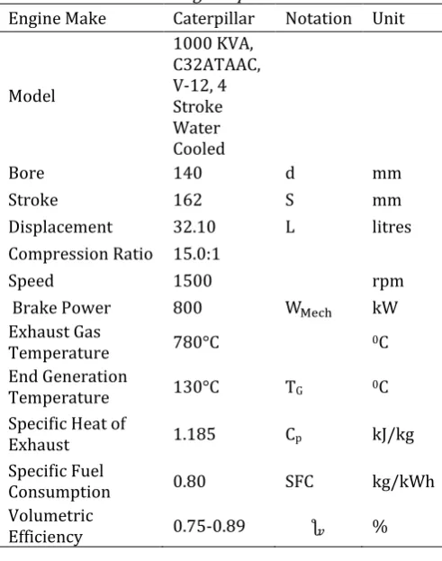
2. MATERIALS AND METHODS
The VARS using the heat energy from the exhaust gas of a diesel engine was considered. The specifications of the engine used as case study for the research are shown in Table 1. The heat energy from the diesel exhaust was calculated. Mathematical modeling was done for each component of the circle considered. Enthalpies and concentrations of ammonia were obtained at different points of the VARS using the saturated ammonia table and also the ammonia-solution enthalpy concentration chart. The capacity of the VARS was then obtained by adding up the total cooling loads obtained with 50% safety factor of the total estimated cooling loads. Finally, the performance of the refrigerating system was measured by varying the absorber, evaporator, condenser and generator temperatures.
2.1 Energy Balance of the Diesel Engine
The main engine of the internal combustion diesel engine loses about 55-60% of its energy to the atmosphere through exhaust, radiation, coolants in form of heat. This clearly indicates the amount of energy present in the fuel that is wasted.
From the first law of thermodynamic:
Taking losses into account:
2.2 Heat Energy Available in Exhaust Gas
The amount of heat energy contained in the exhaust gas is dependent on both the temperature of the exhaust gas and its mass flow rate. The quantity of heat supplied by the exhaust gas to the generator was evaluated with the aid of equation (3) as reported by Jadhao and Thombane [17], and given as [17]:
̇ The mass flow rate of the exhaust gas ( ̇ ) is obtained from:
̇ ̇ ̇
Also, the mass flow rate of fuel ( ̇ and air ( ̇ are obtained from equations 5 and 6:
̇ ̇ ̇ Where the swept volume is calculated from:
̇ ̇
Table 1: Engine specifications
Engine Make Caterpillar Notation Unit
Model
1000 KVA, C32ATAAC, V-12, 4 Stroke Water Cooled
Bore 140 d mm
Stroke 162 S mm
Displacement 32.10 L litres
Compression Ratio 15.0:1
Speed 1500 rpm
Brake Power 800 kW
Exhaust Gas
Temperature 780°C 0C
End Generation
Temperature 130°C TG 0C
Specific Heat of
Exhaust 1.185 Cp kJ/kg
Specific Fuel
Consumption 0.80 SFC kg/kWh
Volumetric
Efficiency 0.75-0.89 %
Table 2: Fish Property
Fish Property Quantity Notation Unit Maximum mass of fish
that can be refrigerated per time
30 tons
Freezing temp. of fish -2 tf 0C
Specific Heat capacity
above freezing 3.187 Cp1 kJ/kgK
Specific heat capacity
below freezing 1.670 Cp2 kJ/kgK
Latent heat capacity of
product 276 kJ/kg
Maximum temperature of product when entering the cold storage
15 tin 0C
Temp. of Product when leaving the storage space
-30 tout 0C
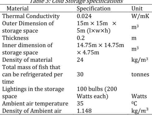
Table 3: Cold Storage specifications
Material Specification Unit
Thermal Conductivity 0.024 W/mK
Outer Dimension of storage space
15m 15m 5m (l w h) m3
Thickness 0.2 m
Inner dimension of storage space
14.75m 14.75m
4.75m m3
Density of material 24 kg/m3
Total mass of fish that can be refrigerated per time
30 tonnes
Lightings in the storage space
100 bulbs (200 Watts each)
Watts
Ambient air temperature 35 0C
Density of Ambient air 1.148 kg/
2.3 Capacity of the Refrigeration System
Capacity of the refrigerating system is the sum total of the heat that can be extracted from the storage space. It is also the product of the mass flow rate of refrigerant and the refrigerating effect of the evaporator. This can be expressed as:
)
The 50 % was used as factor of safety for the refrigeration system in consideration. Thus in obtaining the capacity of the plant, it is necessary to calculate the following cooling loads:
2.4 Product Load
The product considered for the refrigeration is fish product. When the fish is placed in the storage space at a particular temperature which is usually above the temperature of the storage space, the fish will give out heat to the space until its temperature equals the temperature of the storage space. For the fish product, cooling is done from an initial condition tin to its
freezing temperature tf and the heat liberated is given
by [18]:
( ) Also, the quantity of heat given off by the fish product while freezing is given by [18]:
Finally, the quantity of heat given off by the product in cooling from its freezing temperature to the temperature of the storage space is obtained by:
( ) Thus to obtain the total heat given off by the product, we have:
( ) ( )
2.5 Transmission Load
The quantity of heat that penetrated the storage space from outside is the heat gained through the structure of the cold storage space. This forms a considerable part of the total cooling load. The heat gained involves leaks through walls, floor and the ceiling of the cold storage. The heat gain through walls, floor and ceiling is given by [2]:
The overall heat transfer coefficient which is the inverse of the summation of thermal resistance is expressed as:
∑
For unit area [2]:
∑
From equations (12) and (14), we have:
∑
Area, A of fish storage:
For this research, the walls, the floor, the ceiling are considered to be of the same material, thus the thermal resistance is the same for all the sides. The thermal resistance is therefore given as [19]:
( )
2.6 Air Change Load
When freezing starts, the storage space is filled with ambient air which has to be cooled before freezing of the fish product begins. Air change load is due to leakages of the outside air either through door openings or cracks into the refrigerated space. For this research the air change load is obtained by [20]:
2.7 Internal Load
The internal load relates to the heat from electrical energy dissipated in the cold storage space. This includes Electrical Energy from lights, motors, fans etc. However, the only source of internal load considered is the 100 (200Watts) bulbs left on during the 24 hours of refrigeration. And this is given as:
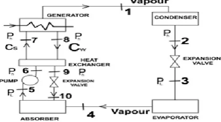
Figure 1: Schematic Diagram of the VARS system analysis
2.8 Thermodynamic Analysis of the Refrigeration System
Assumptions made for the thermodynamic analysis: a) At State Point 4, there is only saturated ammonia
vapour at low pressure.
b) At State point 1, there is only saturated ammonia vapour at high pressure.
c) Pumping is isentropic. d) Expansion is isentropic.
e) Weak ammonia solution contains less percentage of refrigerant and more percentage of absorbent. f) Strong ammonia solution contains more
percentage of refrigerant and less percentage of absorbent.
g) The system is divided into two pressure points (high and low). The high pressure is obtained from the steam table at temperature corresponding to condenser temperature while the low pressure is obtained at the temperature corresponding to the evaporator temperature. h) Evaporator pressure is the same as the absorber
temperature while condenser pressure is the same as the generator temperature.
i) Heat exchanger effectiveness is 1.
Figure 2: Mixing of Fluid Stream under Steady Flow in the Evaporator
2.9 Heat Absorbed in the Evaporator
Heat absorbed in the evaporator is given as:
Applying the law of mass conservation, we have:
The mass flow rate of the refrigerant is given as:
The mass flow rate of the strong solution is given as [21]:
The mass flow rate of weak solution is expressed as [21]:
Figure 3: Mixing of Fluid Stream under Steady Flow in the Condenser
2.10 Heat Rejected in the Condenser Heat rejected in the condenser is given as:
2.11 Circulation Ratio
Circulation ratio is defined as the ratio of mass flow rate of the solution coming from the generator to the mass flow rate of the refrigerant [22].
Figure 4: Mixing of Fluid Stream under Steady Flow in the Absorber
2.12 Heat Rejected in the Absorber
The heat rejected in the absorber is given as:
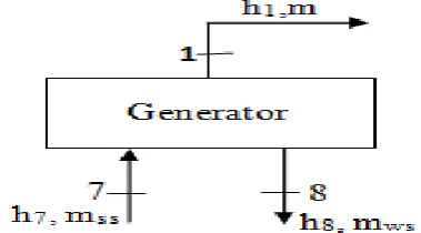
2.13 Heat Supplied in the Generator
The heat supplied to the generator from energy balance is given as [6]:
Figure 5: Mixing of fluid stream under steady flow in the generator
2.14 Coefficient of Performance
The Coefficient of performance (COP) is the ratio of the evaporating effect (cooling loads) to the available heat in the generator.
Alternatively [11],
(
)
2.15 Percentage Heat Energy Utilization
A measure of the heat energy utilized from exhaust gas is done by comparison between the total available heat energy in the exhaust gas and the quantity of heat energy supplied to the generator. And this is given as:
Percentage Energy utilized =
3. RESULTS AND DISCUSSION
s ss ’s s was successfully calculated as 349.69 kW. The heat energy that is supplied to the generator was also obtained as 314.50 kW as seen in Table 6 and this was about 90 % of the heat energy contained in the exhaust. This difference is due to minor losses in heat energy as it is transferred to the generator. The result showed that about 90% of the exhaust gas heat energy was utilized in the absorption VARS. Table 4 shows values
of enthalpies, pressures, concentrations, mass flow rates and temperatures of different properties obtained at various points of the VARS in Figure 1. It shows that at states 1, 2, 3 and 4, the working fluid is purely ammonia. States 5, 6 and 7 give ammonia in water solution, concentration of 0.3 while at states 8, 9 and 10 the solution becomes more of water having concentration of 0.24 with ammonia vapourizing from the solution.
3.1 Capacity of the Refrigeration System
The capacity of the VARS in consideration was obtained by adding up the total cooling load as shown in table 5 and also adding 50% of the total estimated load for safety purposes.
The quantity of heat energy supplied and rejected from the system as obtained from the thermodynamic analysis at the various components of the VARS are as shown in Table 6. The ratio of the total refrigeration load or evaporating effect (QE) as seen in tables 4 and 6
to the heat supplied to the generator gives COPof the VARS as 29.67 %.
Table 5: Values of Cooling Load
s/n Source of heat Cooling Load (KW) 1 Heat from fish Product 130.840
2 Heat through walls, ceiling,
and floor 5.852
3 Heat gain from air change 5.593 4 Internal heat gain from light 20.000
5 Defrost heat load (50% safety Factor) 81.143
Total Refrigeration Load 243.43KW (69.55TR)
Table 4: Thermodynamic properties at each state point
State Points Saturation Pressure (bar) Temperature (oC) Enthalpy, h (kJ/kg) Mass flow
(kg/s) Concentration
1 15.5 40 1473.3 0.235 1
2 15.54 40 371.9 0.235 1
3 1.196 -30 371.9 0.235 1
4 1.196 -30 1405.6 0.235 1
5 1.196 40 80 1.175 0.3
6 15.54 - 80 1.175 0.3
7 15.54 - 419 1.175 0.3
8 15.54 130 490 0.94 0.24
9 15.54 - 110 0.94 0.24
10 1.196 - 110 0.94 0.24
Table 6: Heat Energy Flow
s/n Description Temperature
Notations
Temperature (0C) Values
Heat Energy Notations
Heat Energy ( KW)
1
Total Heat Absorbed by evaporator
TE -30 QE 243.43
2 Heat rejected in condenser TC 40 QC 258.76
3 Heat rejected in
absorber Ta 40 QA 339.72
4 Heat Energy in
Exhaust Gas QEX 349.69kW
5 Heat supplied in
generator TG 130 Qg 314.50
6
Coefficient of performance of VARS
COP 29.67 %
Figure 4: Effect of exhaust gas temperature on Heat generation
Figure 4 shows the variation of waste energy available against the exhaust gas temperature. It shows that waste heat energy available in the exhaust gas is directly proportional to exhaust gas temperature. The quantity of waste heat contained in the exhaust gas is a function of the temperature of the exhaust gas. Higher exhaust temperature influences the rate of heat transfer and also improves the theoretical efficiency of converting thermal energy from heat source to another form of energy such as mechanical or electrical [17]. It is worth noting that increase in generator temperature will give a corresponding increase in enthalpies at state point 8. The relationship between COP and generator temperature is illustrated in Figure 5. It shows that the COP increases with increase in generator temperature. According to Chijioke [23], refrigeration load inlet temperature causes an increase in COP, though the COP will experience a drop at some points owing to irreversibility.
Figure 5: COP versus Generator Temperature
Figure 6 shows a plot of the decrease in circulation ratio against the varying generator temperature. It clearly shows that the circulation ratio decreases rapidly from 4 to 2.3 at first before it started decreasing continuously from 2.3 down to 1.3. This decrease in circulation ratio shows that there was efficient utilization of the generator temperature in converting ammonia into vapour.
The variation in condenser temperature with COP is illustrated in Figure 7. It shows that as the condenser temperature increases, the coefficient of performance decreases. The relationship between the condenser temperature and COP could be seen in equation 30. The increasing condenser temperature steadily slows down the phase change of the vapour refrigerant to liquid.
Figure 7: COP versus Condenser Temperature
Figure 8 gives a graphical illustration of the variation of the evaporator temperature with the COP. It can be seen that the coefficient of performance increases with increase in evaporator temperature. This demonstrates that the evaporator temperature affects the coefficient of performance of the refrigerating system. It therefore implies that effectively and efficiently using the exhaust gas would lead to better performance of the VARS,
Figure 8: COP versus Evaporator Temperature
The performance of the refrigerating system was also measured by varying the absorber temperature. As the absorber temperature increases the circulation ratio changes, therefore, the COP of the system drops. This to a large extent affects the capacity of the pump to effectively pump the required ammonia water solution to the generator due to traces of ammonia vapour formation at that state. Figure 9 shows that the COP of the absorption system varies inversely with the absorber temperature.
Figure 9: Absorber Temperature versus COP
4. CONCLUSION
Vapour absorption refrigeration system has been considered in this research work. And it was observed that the VARS can replace the vapour compression system for cooling in vessels, thus making it a feasible alternative to the conventional VCRS for fishing vessels. Also, in view of the safety concern of some refrigerants, vis-à-vis the environment, the VARS is eco-friendly as it involves the use of ammonia as a refrigerant which does not contribute to greenhouse effect and ozone layer depletion. Also from our results and discussions, it was observed that the heat load needed in the generator for cooling can be achieved with 349.69 kW heat energy from the exhaust gas. With this amount of energy in the exhaust gas, 314 kW is utilized in the generator representing about 90% of the available heat energy. This quantum of heat energy was used to achieve a refrigerating effect of 243.43 kW. VARS is therefore, an achievable and reliable option of energy loss reduction in diesel engines by utilizing the engine waste heat.
5. RECOMMENDATIONS
From the research work, it has been acknowledged that there are large potentials of energy savings through the use of waste heat from diesel engines in general. Therefore, VARS should be an alternative source of refrigeration for fishing vessels.
6. ACKNOWLEDGEMENT
The authors wish to sincerely acknowledge the contributions of Mr. Olabisi, Oluwasogo for setting the bases on which this work was built and successfully executed.
7. REFERENCES
[1] s “ R ”
[2] R j R K “E s” New Delh, 2007
[3] HR E “Heating, Ventilation, and Air Conditioning HV C s”, Atlanta, 2011 [4] Yadav, J. P. and Singh, B. R. Experimental set up of
Air Conditioning System in Automobile using Exhaust Energy. SPS-Journal of Physical Sciences, Engineering and Technology, Vol.5, pp. 71-80, 2014.
[5] R z V “ s s Ex s R P s Onboard Fishing Vessels and Improvement P ss b s” Second International Symposium on Fishing Vessel Energy Efficiency E-Fishing, Vigo, Spain, , pp. 27-32, May 2012.
[6] P k R “Model-Based Heat Recovery For Operating A Vapour Absorption Refrigeration s ” Nigerian Society of Engineering Technical Transaction, Vol. 51, Number 2, pp. 67-74, 2017.
[7] Kharagpur, I. T. 40 Lessons on Refrigeration and Air Conditioning, Unpublished Lecture Note, Indian Institute of technology, India, 2008.
[8] Shekhar, D. T., Prateek, D. M., Rupesh, L. R., and G “C k C b b V Absorption Refrigeration System Using Engine Ex s ” International Journal of Research in Engineering and Technology, Vol.3, Number 5, pp. 816-822, 2014.
[9] “H s ” http: //eprints.utm.my/29014/3/SeyedAhmadTohidiM FM2012CHAP1.Pdf, Accessed on November 27, 2016
[10] s M D s K C “ Refrigeration System for an Automobile Based Vapour Absorption Refrigeration System Using s E E ” International Journal of Engineering Science and Research Technology, pp. 591-598, 2015.
[11] B C “ R Based on Automob C ” International Journal of Emerging Science and Engineering, Vol. 2, Number 7, pp. 32-38, 2014. [12] M K s q “A
Cooling System for an Automobile Based on Vapour Absorption Refrigeration Cycle Using s H E ” Int. Journal of Engineering Research and Applications, Vol. 4, Number 3, pp. 441- 444, 2014.
[13] Poku, R., Ohochuku, P. O. and Oyinki, T. O. “P G s b Plant Us bs R s ” Current Journal of Applied Science and Technology, Vol. 24, Number 6, pp.1-10, 2017. [14] Thakre, S. D., Malwe, P. D. Raut, R. L. and Gawali, A.
“C k C b b V Absorption R s Us E Ex s ” International Journal of Research in Engineering and Technology, Vol. 3, Number 5, 2014, pp. 816-822.
P M D “R E Waste Heat for Reutilization in Air Conditioning s b : I s ” Global Journal of researches in engineering Mechanical and mechanics engineering, Vol. 12, Number 1, pp. 2249-4596, 2012.
[16] Bajpai V K “Design of Solar Powered Vapour bs s ” Proceedings of the World Congress on Engineering, London, U.K., July 4 - 6, pp. 20-24, 2012.
[17] J J b D G “R Ex s G s H R IC E s” International Journal of Engineering and Innovative Technology, Vol. 2, Number 12, pp. 93-100, 2013.
[18] D s D “Modern Refrigeration and Air C E s” New Delhi, 2012. [19] F “ I s B s”
Unpublished Lecture Note, Aalto University, Finland, 2016.
[20] “C L C on for a Potato C ” International Journal of Innovative Research in Engineering and Science, Vol. 3, Number 5, pp. 20-27, 2016.
[21] Aman, S., Abishek, M., Devesh, S. and Karan, C. “C P D Thermodynamics Calculation of Ammonia-water V bs s ” International Journal of Mechanical Engineering and Technology, Vol. 6, Number 9, pp. 72-81, 2015.
[22] B b B Y C “P s s Lithium Bromide Water Absorption Refrigeration System Using Waste Heat of Boiler Flue Gases” International Journal of Engineering Research and Management, Vol. 2, Number 2, pp. 42-47, 2015. [23] Chijioke, N. “Use of Energy Method to Simulate
the Performance of LiBr/H2O bs s ”