PERFORMANCE
PERFORMANCE
PERFORMANCE
PERFORMANCE ANALYSIS OF GSM NETWORKS IN MINNA METROPOLIS OF
ANALYSIS OF GSM NETWORKS IN MINNA METROPOLIS OF
ANALYSIS OF GSM NETWORKS IN MINNA METROPOLIS OF
ANALYSIS OF GSM NETWORKS IN MINNA METROPOLIS OF
NIGERIA
NIGERIA
NIGERIA
NIGERIA
A
A
A
A.... Ozovehe
Ozovehe
Ozovehe
Ozovehe
1111, *, *, *, *and A
and A
and A
and A.... U. Usman
U. Usman
U. Usman
U. Usman
22221 11
1TRIFIELD TECHNOLOGY LIMITED,14ISHAQ MAAJI CRESCENT,GWAGWALADA ABUJA,NIGERIA 2
2 2
2 DEPT. OF ELECTRICAL AND ELECTRONICS ENGINEERING,FEDERAL UNIVERSITY OF TECHNOLOGY,MINNA,NIGERIA. E
E E
E----mail addresses:mail addresses:mail addresses:mail addresses: 1 1 1 1 [email protected] 2222 [email protected]
ABSTRACT
ABSTRACT ABSTRACT ABSTRACT
The performance of a The performance of a The performance of a
The performance of a cellular network is cellular network is cellular network is cellular network is assessed assessed assessed in terms assessed in terms in terms in terms of keyof keyof keyof key performance indicators (KPI) based on statistics performance indicators (KPI) based on statistics performance indicators (KPI) based on statistics performance indicators (KPI) based on statistics generated from drive tests
generated from drive tests generated from drive tests
generated from drive tests orororor network management systems. network management systems. network management systems. However, drive tests give the ‘feel’ of the designed network management systems. However, drive tests give the ‘feel’ of the designed However, drive tests give the ‘feel’ of the designed However, drive tests give the ‘feel’ of the designed network as it is experienced by the subscribers.
network as it is experienced by the subscribers. network as it is experienced by the subscribers.
network as it is experienced by the subscribers. TTTThereforehereforehereforeherefore, it , it , it , it is usedis usedis usedis used in this study to compare performance of GSM in this study to compare performance of GSM in this study to compare performance of GSM in this study to compare performance of GSM operator networks
operator networks operator networks
operator networks (W, X, Y and Z) (W, X, Y and Z) (W, X, Y and Z) (W, X, Y and Z) inininin Minna, Niger State, Nigeria. Minna, Niger State, Nigeria. TMinna, Niger State, Nigeria. Minna, Niger State, Nigeria. TTTransmission Environmental Monitoring ransmission Environmental Monitoring ransmission Environmental Monitoring ransmission Environmental Monitoring System System System System (TEMS)
(TEMS) (TEMS)
(TEMS) drive test tools drive test tools drive test tools drive test tools werewerewerewere used used used used to collect Log fileto collect Log fileto collect Log filessss from to collect Log file from the from from the the the live GSM networks. live GSM networks. live GSM networks. Xlive GSM networks. X network XXnetwork network network was found to have the was found to have the was found to have the was found to have the best performance
best performance best performance
best performance from from from from thethethe analysis the analysis analysis analysis which was which was based onwhich was which was based onbased onbased on target KPIs defined by target KPIs defined by target KPIs defined by Nigerian target KPIs defined by Nigerian Nigerian Nigerian CommunicationCommunicationCommunicationCommunicationssss Commission (NCC)
Commission (NCC) Commission (NCC)
Commission (NCC). A. A. A. All the networks suffered one ll the networks suffered one ll the networks suffered one typell the networks suffered one typetypetype of degradation or the other in terms of of degradation or the other in terms of the of degradation or the other in terms of of degradation or the other in terms of the the the KPIsKPIsKPIs. . . . The KPIs The The The research
research research
research thenthenthenthen ssssuggesteduggesteduggesteduggested the required physical optimization measures such as swapping of RF antenna cables, the required physical optimization measures such as swapping of RF antenna cables, the required physical optimization measures such as swapping of RF antenna cables, the required physical optimization measures such as swapping of RF antenna cables, azimuth adjustment and ret
azimuth adjustment and ret azimuth adjustment and ret
azimuth adjustment and retune of broadcast control channel (BCCH) frequencies une of broadcast control channel (BCCH) frequencies une of broadcast control channel (BCCH) frequencies une of broadcast control channel (BCCH) frequencies in order in order in order in order to resolve the problems to resolve the problems to resolve the problems to resolve the problems identified
identified identified
identified on on on on WWW network Wnetwork network network in this studyin this studyin this study. . . . in this study
Key Key Key
Keywords: words: words: GSM Network, Drive Test, KPI and Radio Frequency Network Optimization words:
1. INTRODUCTION 1. INTRODUCTION 1. INTRODUCTION 1. INTRODUCTION
Wireless mobile communication system has grown from the first generation (1G) of analogue system, through the second generation (2G) of digital system to the ever maturing third generation (3G) high speed multiple service system [1] and has transformed the ease of communication the world over. However, the widespread use of mobile communications has heightened consumer demand for better quality service. Thus, network operators the world over, face the challenges of improving the quality of service while increasing capacity and rolling out new services as they provide wider coverage at the same time had lead to 4G ( fourth generation) as the fourth generation of mobile telecommunications technology, succeeding 3G and preceding 5G ( fifth generation) and 6G (sixth generation). A 4G system support applications like amended mobile web access, IP telephony, gaming services, high-definition mobile TV, video conferencing, 3D television, and cloud computing in addition to the usual voice and other services of 3G. Two 4G candidate systems are
commercially deployed: the Mobile WiMAX and Long Term Evolution (LTE) [8].
Performance and quality of service (QoS) evaluation are the most important to the mobile operators as the revenue generation and customer satisfaction are directly related to network performance and quality. The Network needs to be under continuous monitoring and control to maintain and improve the performance of the system [2]. Usually, statistics generated from drive tests or network management systems are used to unravel network problems and provide useful recommendations to resolve them. This process called radio frequency (RF) optimization is continuously required as the network evolves. Through RF Optimization, the quality of service and usage of the network resources are greatly improved and the balance between coverage and capacity is achieved using existing network resources. In some cases, upgrading of existing resources or additional resources may be required to meet the ever increasing demands for QoS [3, 4].
Drive test trial is the most common way to analyze cellular network performance as it provides
Copyright© Faculty of Engineering, University of Nigeria, Nsukka, ISSN: 1115-8443
www.nijotech.com
360
subscriber perspective to the service provider. Thetrial basically collect measurement data from a live network with the sole aim of analyzing and evaluating the test result so as to undertake possible network optimization for performance improvement [3], and in this work TEMS (Test Mobile System) equipment was used to investigate: non–working transceivers(TRXs); inactive radio network features like frequency hopping; overshooting sites coverage overlaps; coverage holes; carrier-to-interference (C/I) analysis; high Interference spots; poor handover; accessibility and retainability of the network etceteras.
This work is an effort to compare the performance of various GSM operator network in Minna Metropolis. This is done with network performance metrics obtained from drive test log files. This work also helps to validate the claim made by the NCC QoS audit report which said that X has the best network quality nationwide [5] as obtained from network operating centre (NOC) statistics.
More in-depth analysis was made on X network and based on our findings; possible steps to improve this network are made.
2. 2. 2.
2. GSM KEY PERFORMANCE INDICATOR GSM KEY PERFORMANCE INDICATOR GSM KEY PERFORMANCE INDICATOR GSM KEY PERFORMANCE INDICATOR
The performance of cellular radio networks can be measured using different KPIs. For effective radio network optimization, it is necessary to pre-select relevant KPIs to focus on, and observe closely when the network monitoring process is going on.
The most important of the KPIs from the operator’s perspective as described in [6] include bit error rate (BER), frame erasure rate (FER), bit error probability (BEP) and mean opinion score (MOS). However, the main KPIs that are used by NCC for rating the quality of service of cellular networks in Nigeria [5] are:
i. CallCallCallCall setup setup setup setup success ratesuccess ratesuccess ratesuccess rate (CSSR)(CSSR)(CSSR)(CSSR) - this indicator measures the ease with which calls are established or setup. The higher the value, the easier it is to set up a call. High call setup success rate is achieved when standalone dedicated control channel (SDCCH) seizures and traffic channel (TCH) allocation are easily achieved to set up a call. It is calculated as number of the unblocked call attempts divided by the total number of call attempts.
ii. CCCall Call all drop all drop ratedrop drop raterate (CDR)rate(CDR)(CDR)(CDR) - this indicator, also called Drop Call Rate (DCR) measures the network ability to retain call conversation when it has been established or setup. A dropped call is a call that is prematurely terminated before being
released normally by either the caller or the callee. Dropped calls can be caused by degraded signal quality around the vicinity of a mobile phone, interference, unsuccessful handover attempt to neighbor cells, hardware faults and coverage issues. A value of 3% means that out of every 100 calls established only 3 will drop before any of the calling parties voluntarily terminate the call. It is calculated as the number of dropped calls divided by the total number of call attempts.
iii. SDCCH congestion rateSDCCH congestion rateSDCCH congestion rateSDCCH congestion rate - this indicator measures the availability of signaling capacity to set up a call, its acceptable value is supposed to be as low as 0.2% or less. This congestion is experienced when the network is burdened with high number of location update requests, high number of short message (SMS) traffic or in scenarios where so many subscribers are trying to setup calls at the same time without enough SDCCH resources to support these requests. This indicator measures the ease with which a call can be setup, the ease with which we can recharge our account, send SMS, location update, paging and etceteras. iv. TCH congestion rateTCH congestion rateTCH congestion rateTCH congestion rate - this indicator measures the
relative ease with which a traffic channel can be seized to set up a call after a signaling seizure has been successful. The higher this value, the higher the relative difficulty it is in making a call. Traffic channel congestion is caused by unavailability of TCH channels. This congestion is the first level of congestion experienced by the consumer. In a properly dimensioned network the value of this metric should not be more than 2% per cell. v. TCH congestion rateTCH congestion rateTCH congestion rateTCH congestion rate - this indicator measures the
relative ease of seizeing a traffic channel to set up a call after a signaling seizure has been successful. Because of the mobility in GSM networks, there might be reasons to handover already established calls to another base station in order to retain the call. This requires the request for traffic channel assignment from a neighboring cell. If this request fails, the call is dropped and the consumer experiences a drop call while the system congestion counter is incremented. In a properly dimensioned network the value of this metric should not be more than 2%.
Channel coding Decoding
MOS
Speech Codec
FER
BER BEP
CDR
CSSR HSR
Figure 1: Measurement Points for Main Speech Key Performance Indicators
Table 1: NCC KPIs Target for Cellular Mobile Network
Key Performance
Indicator CSSR CDR HSR SDCCH Cong CCR TCH Cong
NCC Target (%) 98 2 98 0.2 96 2
These indicators are not only utilized to measure the network performance but can also be used by the network for multiple radio resource management functions, such as paging, network access, congestion, call drop, handovers, power control, adaptive multi-rate codec (AMR) link and channel mode adaptation, GPRS link adaptation and etceteras. Based on the analysis of these KPIs, tuning and optimization suggestions are provided to resolve network problems. The target set by NCC for some of these KPIs are shown in Table 1 [5].
3. 3. 3.
3. MATERIALMATERIALMATERIALMATERIALSSSS AND METHODAND METHODAND METHODSAND METHODSS S
The drive test was performed using TEMS Investigation tools setup as shown in Figure 2. The information provided is displayed in status windows of the TEMS. This information includes cell identity, base station identity code (BSIC), absolute radio frequency channel number (ARFCN), mobile country code, mobile network code and the location area code (LAC) of the serving cell is also information about RxLev (Received signal strength - power level), BSIC and ARFCN for up to six neighboring cells; channel number(s), timeslot number, channel type and time division offset; channel mode, sub channel number, hopping channel indication, mobile allocation index offset and hopping sequence number of the dedicated channel; and RxQual, FER, discontious transmission (DTX) down link, Speech Quality Index (SQI), timing advance (TA), transmit (TX) Power, radio link timeout counter and carrier-to-adjacent (C/A) channel parameters for the radio environment.
Figure 2: Basic TEMS Drive Test Tools used for Log File Collection
Nigerian Journal of Technology, Vol. 34, No. 2, April 2015
362
Table2: A typical cell ref format
Cell BCCH BSIC Lat Lon MCC MNC LAC CI ANT DIRECTION ANT BEAM WIDTH
VI003A 101 16 9.63 6.53 621 20 522 10003 0 65
VI003B 105 16 9.63 6.53 621 20 522 20003 120 65
VI003C 110 16 9.63 6.53 621 20 522 30003 240 65
VI010A 102 10 9.62 6.55 621 20 522 10010 0 65
VI010B 110 10 9.62 6.55 621 20 522 20010 120 65
VI010C 114 10 9.62 6.55 621 20 522 30010 240 65
VI010D 750 10 9.62 6.55 621 20 522 40010 0 65
VI010E 748 10 9.62 6.55 621 20 522 50010 120 65
VI010F 754 10 9.62 6.55 621 20 522 60010 240 65
Figure 3: Drive Test Route Used for the GSM Networks in Minna Metropolis
The mobile station (MS) was placed inside the car during the drive test and no external antenna was used. Two different measurement methods were used to collect the log file for this performance analysis, namely, short and long calls.
i. Short calls were used to collect accessibility statistics. A short voice call attempt was performed every 50 seconds, including 10 seconds of idle time between two consecutive calls. A script in the TEMS Investigation logging tool automatically initiates the short calls. An event “Call Attempt” was generated every time the script triggered a new call attempt (meaning
a number was dialled). The other event “Blocked Call” was generated every time the call setup procedure failed.
ii. Long calls were used to obtain retainability statistics. Long voice calls were established automatically and were ended by blocks, drops or normal user release. TEMS Investigation tool generated an event “Drop Call” every time the connection dropped. In this drive test, the long call was programmed in the command sequence to end after 120 seconds.
satisfaction of a user of the service [10]. The quality of a radio network can be evaluated by examining the KPIs such as: Signal quality (RX Qual), Speech quality index (SQI), Dropped call ratio (SDCCH and TCH), MS and BTS power levels, RX-level [11].The BER is an estimated number of bit errors in a number of bursts to which corresponds a value from 0 to 7 (best to worst) of the RX Qual. RX-Qual reflects the average BER over a period of 0.5s and it does not capture many phenomena that affect the listener’s perception of speech quality. That is why other metrics are defined to take care of factors that RX-Qual does not consider which [12] are:
i. Rx-Level is defined as the power level corresponding to the average received signal level of the downlink as measured by the mobile station. The range of Rxlevel is between 55 to -110. Level lower than -70 shows low signal levels, normal range is from -30 to – 70. It is been further classified as Rx-Level Sub and Rx-level Full. ii. Frame Erasure Rate (FER) is a speech quality
degrade factor that indicates fading and interference. Voice quality is judged upon the Frame erasure rate.
iii. Speech Quality Index (SQI) SQI is an estimate of the perceived speech quality as experienced by the mobile user, is based on handover events and on the bit error and frame erasure distributions. Log file can easily be analyzed by: post processing of data; plotting RxLev; RxQual, speech SQI and FER for overall picture of the driven area. The usual action to be taken for the network after drive test are: defining
missing neighbor relations; proposing new sites or sector additions with before and after coverage plots; proposing antenna azimuth changes; proposing antenna tilt changes; proposing antenna type changes; BTS equipment/filter change; re-tuning of interfered frequencies etc [3].
The analysis was performed for the test areas (From Minna Trade Fair Complex through Ladi Kwali road to Prison Service Office and linked to Tudun Fulani area. Kuta road to Maitumbi area was also drive test. The areas are shown in Figure 3 based on the log file collected with TEMS Investigation shown in Figure 2.
4. RESULT 4. RESULT4. RESULT 4. RESULT
The coverage penetration level of signals of W, X, Y and Z network in different parts of Minna Metropolis is shown in Figures 4 to 7.
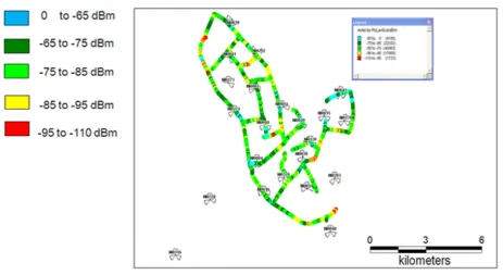
Some of the KPIs plotted are RxQual, RxLev, SQI and FER as shown in Figures 8 to 11. The Rx Lev values, between 0 to 65dBm indicates excellent coverage; -65 to -75dBm is very good; -75 to -85dBm is good; -85 to -95dBm is average and -95 to -110dBm is poor. Below -110dBm it is assume there is no coverage. A value of RxQual between 100% to 95% indicates excellent quality; and less than 95% indicates poor quality. Also, values of SQI greater than 16.5dBQ is good; between 16.5dBQ to 4.5dBQ is acceptable and below 4.5dBQ . Summary of all events that happened during the drive test on each network is shown in Tables 3 and 4.
.
Nigerian Journal of Technology, Vol. 34, No. 2, April 2015
364
Figure 5: Z network coverage penetration in Minna Metropolis
Figure 6: Y network coverage penetration in Minna Metropolis
Figure 7: X network coverage penetration in Minna Metropolis
Figure 8: Summary of RxQual Figure 9: Summary of RxLev sub (dbm)
Figure 10: Summary of SQI Figure 11: Summary of FER
Table 3: Summary of Call Events and KPIs for W and Z Network
Nigerian Journal of Technology, Vol. 34, No. 2, April 2015
366
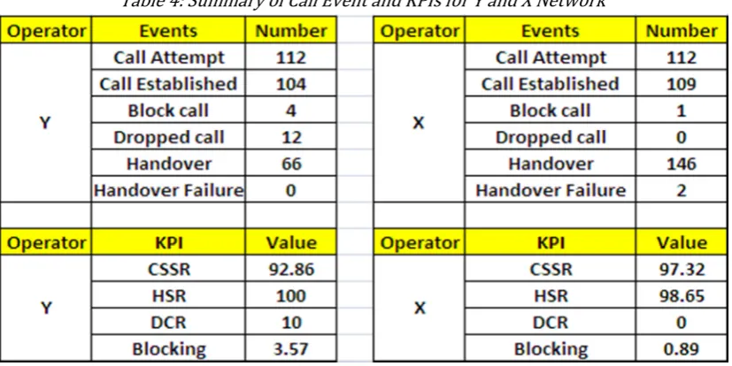
Table 4: Summary of Call Event and KPIs for Y and X Network
Table 5: Ranking of various network quality using NCC KPIs target
OPERATE W Z Y X GENERAL RANKING W RANKING
RX Level(>75dBm) 43.55 55.82 71.46 73.78 X 4th
RX Qual(0-5) 88.78 87.12 50.82 95.67 X 2nd
SQI(16-30) 94.89 79.87 93.06 94.66 W 1st
CSSR 89.38 93.75 92.86 97.32 X 4th
HSR 97.1 95.63 100 98.65 Y 3rd
CDR 0.98 0.94 1.0 0 X 3rd
Call Blocking 1.77 3.57 3.57 0.89 X 2nd
5. DISCUSSION 5. DISCUSSION 5. DISCUSSION 5. DISCUSSION
Using NCC KPIs target as defined in Table 1, the summary of the log file analysis best ranking and comparative X ranking is shown in Table 5.
Considering the number of blocked calls, dropped calls and handover failure in Table 3 and 4, it is obvious that Y has the worst network quality followed by Z in the Metropolis while X has best network quality followed by W. Y however, has the best planned network requiring minimal handover and hence 100% handover success rates. W network ranked fourth in terms of Rx Lev, CSSR and third in HSR as well as CDR. However, because of the lack of access to cell reference data of other networks, further in-depth analysis and recommendations was only possible on W network.
The W sites that were on air during this drive test are identified as: VI0003, VI0004, VI0010, VI0011, V10014, VI0015, VI0016, VI0038, VI0039, VI0040,
VI0041, VI0042, VI0044, VI0316, VI0328, VI0283, VI0370, VI0338, VI0270, VI0274, VI0273 and VI0292. The log file analysis showed that some of these sites need optimization in order to improve the network quality. The problems that affected the sites and the optimization measures required to resolve the problems are recommended in Table 6.
6 66
6. LIMITATION. LIMITATION. LIMITATION. LIMITATIONSSSS
One of the challenges that militate against Teletraffic Engineering research in Nigeria is the unwillingness on the part of network providers to allow researchers unfiltered access to their database. This makes researchers to resort to network simulation instead of using real-live network statistics. So, we could not get comprehensive cell reference data for X, Y and Z networks. Hence, in-depth analysis could not be done on these networks as was done for W network.
Table 6: Summary of optimization recommendation
SITE ID PROBLEM SUGGESTION RECOMMENDATION
VI0040 AZIMUTHAND SWAPPED
CHECK ANTENNA AZIMUTH AND SWAPPED BETWEEN SECTOR D/F
CONFIRM THE SWAPPED AND CORRECT IT
VI0038 AZIMUTH CHECK AZIMUTH FOR SECTOR C/F COFIRM AZIMUTH AND
COORDINATE
VI0044 SWAPPED ALL SECTOR SWAPPED A/B/C CONFIRM THE SWAPPED
AND CORRECT IT
VI0283C AZIMUTH CHECK AZIMUTH AND TILT COFIRM AZIMUTH
VI0041 SWAPPED ALL SECTOR SWAPPED D/E/F CONFIRM THESWAPPED
AND CORRECT IT
VI0270 SWAPPED ALL SECTOR SWAPPED A/B/C CONFIRM THE SWAPPED
AND CORRECT IT VI0016A INTERFERENCE
VI0016A BCCH 112,BSIC 27 AND VI0370C BCCH 111,BSIC 25 ARE HAVING ADJACENT
INTERFERENCE
FREQUENCY ADJUSTMENT IS ADVICED
VI0044A INTERFERENCE VI0044A BCCH 104, BSIC 04 AND VI0338A BCCH 15 ARE HAVING ADJACENT INTERFERENCE
FREQUENCY ADJUSTMENT IS ADVICED
6. CONCLUSION 6. CONCLUSION 6. CONCLUSION 6. CONCLUSIONSSSS
Optimization is a continuous process and RF teams ought always to try and improve the quality of the network by making necessary configuration changes to enhance network performance.
From the comparative analysis done in this study, Y has the worst network quality while X has best network quality followed by W.
This work also helps to validate the claim made by the NCC QoS audit report [5] which said that X network has the best network quality nationwide as obtained from network operating centre (NOC) statistics.
The recommendations in Table 6 need to be implemented so that post-drive test can be done to evaluate the performance improvement that is achieved in the network quality.
7. REFERENCE 7. REFERENCE 7. REFERENCE 7. REFERENCESSS S
[1] Yong X., “Resource Management and QoS Control in Multiple Traffic Wireless and Mobile Communication Systems”, MSc Thesis, University of Cincinnati, 2005.
[2] Pavan Kumar V.S., Anuradha.B., Vivek and Naresh, “ Improvement of Key Performance Indicators and QoS Evaluation in Operational GSM Network”, International Journal of Engineering Research and Applications (IJERA) ISSN: 2248-9622 www.ijera.com Vol. 1, Issue 3, pp.411-417.
[3] Goksel S., “Optimization and Log File Analysis in GSM”, available at http://xa.yimg.com/kq/ groups/19564168/1199781837/name/Drive+Test
+Problem+Analysis.pdf.
[4] Sireesha B.V., Varadarajan S., Vivek and Naresh, “Increasing of Call Success Rate in GSM Service Area Using RF Optimization”, International Journal of Engineering Research and Applications (IJERA) ISSN: 2248-9622 www.ijera.com Vol. 1, Issue 4, pp. 1479-1485.
[5] Nigeria Communication Commission, Retrieved May 4, 2014 from: http://www.ncc.gov.ng/ index.php?
option=com content&view =article&id =332&
Itemid=104 .
[6] Mishra, A. R., “Fundamentals of cellular Network planning and Optimisation”, John Wiley and Sons, 2004.
[7] Timo, H.; Javier ,R. and Juan M., GSM, GPRS and EDGE Performance, Evolution towards 3G/UMTS, 2nd Edition, John Wiley and Sons, 2003.
[8] International Telecommunication Union, World Radio communication Seminar highlights future communication technologies, Retrieved December 26, 2014 from: http://en.wikipedia.org/wiki/4G. [9]Nokia NetMonitor Manual, Version 0.95, 11.11.2002. [10] ITU-T Rec. E.800, “Terms and Definitions Related to
Quality of Service and Network Performance Including Dependability,” Aug. 1993. [11] Joseph Isabona, ‘’Maximising Coverage and
Capacity with QOS Guarantee in GSM Network by Means of Cell Cluster Optimization’’ International Journal of Advanced Research in Physical Science (IJARPS) Volume 1, Issue 6, October 2014, PP 44-55 ISSN 2349-7874 (Print) & ISSN 2349-7882 (Online)
www.arcjournals.org