TECHNO-ECONOMIC INVESTIGATION OF DIFFERENT ALTERNATIVES OF
IMPROVING SIMPLE GAS TURBINE INTEGRATION OPTIONS
M. A. Sulaiman
1,*, M. A. Waheed
2, W. A. Adesope
3and A. Noike
41,
M
ECHANICALE
NGINEERINGD
EPARTMENTO
LABISIO
NABANJOU
NIVERSITYA
GOI
WOYE,
O
GUNS
TATE,
NIGERIA.
2,M
ECHANICALE
NGINEERINGD
EPARTMENTF
EDERALU
NIVERSITY OFA
GRICULTUREA
BEOKUTA,
O
GUNS
TATENIGERIA.
3,
O
YOS
TATEC
OLLEGE OFA
GRICULTURE ANDT
ECHNOLOGYI
GBOORA,
O
YOS
TATE,
NIGERIA.
4,
M
ECHANICALE
NGINEERINGD
EPARTMENT,
O
GUNS
TATEI
NSTITUTE OFT
ECHNOLOGYI
GBESA,
O
GUNS
TATE,
NIGERIA.
Email addresses
:
1[email protected]
,
2[email protected],
3[email protected],
4
[email protected]
ABSTRACT
This study investigated the effect of integrating various models proposed to improve a simple gas turbine power plant. A computer program was developed in Matlab software was used to simulate the performance parameters. The energy and exergy analysis of the plant was carried out. The energy and exergy analysis result revealed that both energy and exergy efficiency of plant is low as a result three improvement options were considered. They include Model 1: reducing inlet air cooling (IAC) of the compressor by using the wasted energy in the natural gas pressure drop station. Model 2: recovering wasted energy in the exhaust through heat recovery steam generator (HRSG) and injecting steam into the combustion chamber and lastly Model 3: by combining the two methods. The result showed that among the three methods of improving the plant investigated Model 3 was found to boost power output of the plant from 28.3 MW to 78.4 MW while the thermal and exergetic efficiency improved by 25.5 and 23.6% respectively. Furthermore, from economic and environmental point of view, the lowest levelized cost of electricity as well as the specific emissions was observed in Model 3. Consequently, Model 3 is selected as the best option in improving the simple gas turbine.
Keywords: Gas turbine, inlet air cooling, heat recovery steam generator, energy, exergy and power plant
1. INTRODUCTION
The world electricity demand is predicted to increase by more than two-thirds over the period 2011-2035 according to World International Energy Agency [1]. This implies that the power sector will represent over half of the global primary energy use. This increase demand will be marred with more energy consumption which will consequently result in emission if adequate measures are not put in place. Therefore, it is important to find improved technologies for power generation with high electrical efficiencies and specific power outputs, low emission of pollutants and economical for a sustainable use of fuel.
Presently, 80% the world electricity is generated from fossil fuels (coal, petroleum, fuel-oil, natural gas) fired thermal power plants while the remaining 20% is compensated from different sources such as hydraulic, nuclear, wind, solar, geothermal and biogas [2]. Steam and gas turbine power plants dominate the thermal power generation. The demand for gas turbine power
plant has been on the increase. In fact according to United State Department of Energy it accounted for 15 % in 1998 and it is expected to account for 40 % of US generation by 2020 [3,4]. The reason for this is because of its low capital cost, high flexibility, high reliability without complexity, short delivery time, and fast starting and loading. However gas turbines power plants have typically low efficiency in the range of 20-30%.
In response to this low efficiency several researches have been done and are ongoing to improve its efficiency as well as its environmental impact. Several analyses have been conducted to improve the Simple Gas Turbine (SGT) low thermal efficiency [5, 6, 7, 8]. (Their investigation revealed that ambient temperature, humidity and pressure are important factors affecting SGT performance, as well as very high work ratio and exhaust temperature of around 500oC. This high exhaust
temperature indicates that energy is been wasted into the environment. In recent time, efforts to improve power generation capacity or/and efficiency of a SGT has Copyright© Faculty of Engineering, University of Nigeria, Nsukka,
Print ISSN: 0331-8443, Electronic ISSN: 2467-8821 www.nijotech.com
been through gas to gas recuperation, steam injection (STI), evaporation cycle, chemical recuperation, inlet air cooling (IAC) and combined cycle [6, 7].
Of the aforementioned gas turbine improvements technologies, STI, IAC and combined cycles have witnessed better applications. STI involves the use of heat recovery steam generator (HRSG) to recover the wasted heat of the gas turbine exhaust using pressurised water there after injecting it into the combustion chamber. While IAC is the cooling of the inlet compressor air which has been achieved by fogging, evaporative coolers, absorption chiller amongst other methods. Combined cycles involve combination of Brayton cycle with a medium or low temperature bottoming cycle (Rankine cycle).
Several researches have been carried out in cooling the ambient temperature. Ameri and Hejazi [9] enhanced the Chabahar power plant by using a steam absorption chiller to cool the intake air and their result showed that the output power increased by 11.3%. Ehyaei et al. [11] examined the effect of inlet fogging system on Shahid Rajaee power plant, found that the average output power production increased. In Bangkok, Boonnasa et al. [11] enhanced a combined cycle power plant using steam absorption chiller methodology of IAC to cool intake air to 15oC and 100% humidity, the result showed an
increased in the power output of the plant by 14%. Yang et al. [12] evaluated two different methods of AIC technologies chilling and fogging using parameters such as efficiency ratio, profit ratio and relative payback period. Their result showed that fogging is a better technology. In the investigations of Zurigat et al., [13] using chilled water and ice storage to cool the inlet air temperature of gas turbine it was found to be uneconomical. Farzaneh-Gord and Deymi-Dashtebayaz [8, 14] used a different IAC method which uses the wasted energy of the natural-gas pressure drop station to cool the inlet coming air of the compressor in order to improve performance of Khangiran refinery gas turbine. In this case the cooling is achieved by using the effects of cooling capacity of the refinery natural-gas pressure drop station and the result of their work showed a significant increase in power output and thermal efficiency.
Steam injection technology has also been used to enhance the performance of SGT. Ghazikhani et al. [15] investigated the effect of steam injection in Mashad Power Plant GE-F5 gas turbine and discovered the plant thermal efficiency as well as the back-work ratio increased by 10 % and 15% respectively. Bouam et al. [16] enhanced a SGT under Sahara condition by injecting steam into the combustion chamber. In this study the efficiency of the SGT was held constant at 50% while the ambient temperature was varied from ISO conditions to
50°C. This study has been able to show that it is possible to achieve this high efficiency as a result of steam injection. Traverso and Massardo [17] assessed the performance of four different types of technologies, STIG, regenerated water inject (RWI) cycle, humid air turbine (HAT) cycle and humid air water injection turbine (HAWIT) using thermo economic module program (TEMP) code and concluded that HAWIT is the most attractive combined cycle. Ziółkowski [18] investigated the effects of steam injection on a gas turbine and combined power plant performance on PGE Gorzow power plant using COM-GAS code and Aspen plus commercial package. Poullikkas [20] reviewed current and future sustainable gas turbine technologies by comparing their thermodynamic characteristic and concluded that mixed air steam technologies offered superior performances compared to other technologies. Wang and Chiou [6], and Agarwal et al.[21] combined STIG and IAC techniques in achieving more than 70% boost in power and 24% improvement in heat ratio using the concept of absorption chiller and fogging techniques respectively for reducing the inlet coming air. Poullikkas [20] and Nishida et al., [22] have shown that combining steam injection with AIC techniques offers the highest generating efficiency, reduced NOx emissions and the least exergy via the flue gases while its retrofitting does not destroy its original integrity. While Wang et al., [6] work revealed that the combination of STIG and AIC are economically competitive. Although many research efforts have been expended to apply the STIG and IAC technology to enhance the gas-turbine’s performance, little or no information is available on the use of natural gas wasted energy in achieving AIC combined with STIG. Therefore this study intends to investigate the techno-economic effect of integrating AIC, STIG, combined cycle and Combined AIC and STIG technologies into Olorunsogo power plant in Nigeria.
1.1 Plant Description
2
3
4 5
6 7
AC GT
CC
Gen
1
Figure 1: Schematic Diagram of SGT Power plant
Key: AC - Air Compressor; CC - Combustion Chamber; GT - Turbine; Stream 1 = AC input conditions, stream 2 = AC outlet conditions, stream 3 air inlet from the environment, stream 4 GT inlet conditions, stream 5 =
GT exit conditions stream 6 = shaft connection AC and GT and stream 7 = shaft connection GT to Generator
2. METHODOLOGY
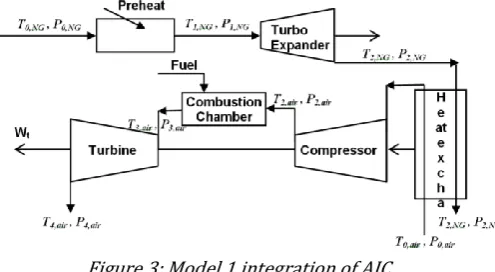
In this study a computer program is developed using Matlab version R2012a software and validated by comparing the result with the plant data. The mass, energy and exergy balances for control volumes were used to investigate the gas power plant. The process flow implemented in MATLAB is shown in Figure 2. All inputs were taken from the collected data from Olorunsogo power plant.
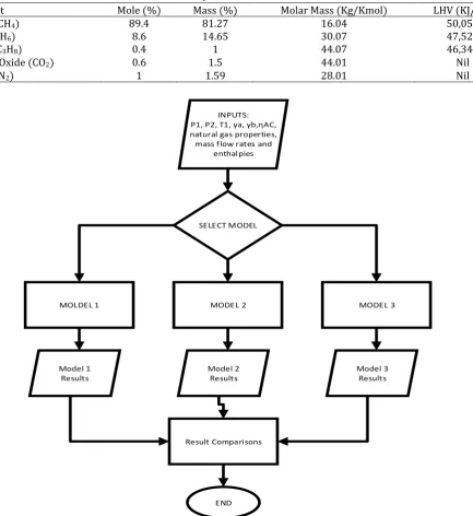
Table 1 Composition of Natural Gas
Component Mole (%) Mass (%) Molar Mass (Kg/Kmol) LHV (KJ/Kg)
Methane (CH4) 89.4 81.27 16.04 50,050
Ethane (C2H6) 8.6 14.65 30.07 47,520
Propane (C3H8) 0.4 1 44.07 46,340
Carbon IV Oxide (CO2) 0.6 1.5 44.01 Nil
Nitrogen (N2) 1 1.59 28.01 Nil
INPUTS: P1, P2, T1, γa, γb,ηAC, natural gas properties, mass flow rates and
enthalpies
SELECT MODEL
MOLDEL 1 MODEL 2 MODEL 3
Model 1 Results
Model 2 Results
Model 3 Results
Result Comparisons
END
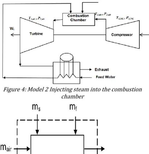
Figure 3: Model 1 integration of AIC
2.1 Compressor
The compressor compression ratio (
r
c) can be definedas [15]
1
where P1 and P2 are the compressor inlet and outlet air
pressure respectively. The isentropic efficiency for compressor and turbine are in range of 85 to 95% as expressed as [8]. The outlet temperature of compressor is calculated from equation [2] as given by Farzaneh-Gord and Deymi-Dashtebayaz [8].
(1
( ⁄ )
1
) 2
where the
a and
gare the expansion ratio of compressor and turbine, and they are 1.4 and 1.3 respectively as expressed by Ibrahim et al. [24]. Also T1and T2 is inlet and outlet temperature of the air
compressor and ηAC is the air compressor efficiency.
Assuming an adiabatic compression, the consumed power of the air compressor is expressed as [23]:
̇ ̇ 3
2.2 Combustion chamber (CC)
The energy balance of CC is given as [24]:
2.3 Gas turbine (GT)
In similar way to the air compressor, the isentropic outlet temperature of the gas turbine is determined and as the energy balance of GT is given as:
The work done by the turbine is given as;
̇ 5
Where,
In (5), is the mass flow rate of fuel and is the mass flow rate of air. The net power output is given as:
6
Here Wnet is the net power output of the plant, WGT is the
Work of gas turbine and WAC is the work of compressor.
The calculation techniques for various technology of improving the SGT are as follows:
2.3.1 Procedure for improving SGT using air inlet cooling (AIC) by natural gas cooling effect:
In Nigeria the natural gas is transmitted via pipe line in a pressure range of 5-7 MPa. This gas pressure has to be reduced at a pressure drop station before entering the gas turbine combustion chamber. These involve the passage of the natural gas through series of throttle valves in which pressure reduced to 1.4 MPa by this method a lot of energy is wasted. However, this energy wasted can be used to generate power by introducing heat exchanger and turbo-expander as shown in Figure 3. Figure 3 is described as follows: the natural gas with high pressure is preheated to 110oC in the preheater to
prevent hydrate formation. Thereafter it passes through the turbo expander and by the time the natural gas leaves the turbo expander the temperature and pressure will be low, thereby creating a cooling effect in the heat exchanger that brings in the fresh air to the air compressor. In the turbo expander a work output is
generated
W
rev
. The reduction the input temperature will lower the air compressors work consequently increasing the network output of the plant. Therefore, the netpower output in this Model will be the addition of turbo expander and gas turbine power output [24]. Furthermore, it should be noted that the natural gas from the heat exchanger will be the fuel to run the gas turbine plant at the required conditions. The natural gas is heated to 110oC to prevent hydrate forming and the
quantity of heat required is estimated from:
̇ ̇ ( )
where ̇ is the quantity of heat required to heat the natural gas, while h is the enthalpy and i and o signifies input and output. The first law of thermodynamics (FLT) is applied to estimate the amount of obtainable work from the turbo-expander. This is gotten from the input temperature and pressure and it is as follows [8, 14]:
11
} 8
1.
}
where NG is natural gas, S is entropy and h is enthalpy. Therefore, the maximum amount of work which may be produced by the turbo-expander is calculated as
̇ ( ) 1
power can be extracted from high-pressure natural gas stream with an exergetic efficiency approaching 75% when utilizing turbo-expanders. Considering the shaft and mechanical efficiency as well as generator efficiency, ϵ = 0.85 was selected in this study. Based on this efficiency
̇ ̇ ̇ ( ) 11
̇ ̇
⁄
1.
} 12
With
T
2,NGthe compressor air inlet temperature can becomputed. In this study, a cross flow gas-to-gas heat exchanger has been proposed to cool ambient air temperature to compressor inlet-temperature. Implementing the definition of heat exchanger effectiveness as found in equation 13 [26].
( )
( )
13
where, cp is the constant pressure specific heat and
( ) 1
By rearranging Equation 13, the model for computing compressor inlet temperature can be obtained as
( )
15
In this study, the heat exchanger effectiveness is fixed at
h
= 0.8 because it is readily available in the market. Gas to gas heat exchanger will be used in this case so that cost of procurement will be low.Once the
T
1,airis obtained the corresponding enthalpycan be obtained to find the corresponding work of AC, the net power output and consequently the efficiency.
2.3.2 Procedure for improving gas turbine by steam injection into the combustion chamber using heat recovery steam generator (HRSG)
The proposed steam injection schematic diagram is represented in Figure 4.This approach uses wasted energy at the exhaust of the gas turbine which is rejected into the atmosphere at a temperature above 500oC to
heat up the compressed water. This is made possible by the heat recovery steam generator (HRSG) where energy is transferred from the exhaust gases to the boiler feed water. The steam is then injected into the combustor. The injected steam increases the mass flow rate through the expander and so that the power output and efficiency of the turbine increases.
In the study, the outlet condition of HRSG will be investigated between 320oC to 500oC at a fixed pressure
of 2.0 MPa. The pressure was fixed because of the pump is commercially available. In order to estimate energy required to heat compressed water from ambient
condition to optimum point, it is important to know the temperature of the exhaust (flue gas). Calculation procedure for estimating the available wasted heat from the exhaust of the gas turbine is [27].
̇ 16
The next step is to calculate the energy required to heat the water to the optimum temperature using equation 17
̇ ( ) 1
The injection of compressed steam into the combustor leads to certain changes. The change in parameters in the combustion chamber can be evaluated by applying the steady flow energy equation (SFEE) and it is represented in Figure. 5.
The energy balance equation for the combustor after injecting the steam will be
̇ ̇ ̇
( ) 18
where tinj and tcc are injected and combustion chamber
respectively. The air fuel ratio of this reaction becomes [16].
( ) ( )
1
The power output is expressed as the difference between the turbine and the compressor power
( )( ) ( ) 2
With the new mass flow rate mf obtained, the new
turbine work (WGT) is obtained and corresponding net
power output Wnet and consequently the efficiency of the
plant can be obtained.
Figure 4: Model 2 Injecting steam into the combustion chamber
2.3.3 Procedure for improving gas turbine by integrating AIC using natural gas cooling capacity and steam injection.
The integration of AIC using natural gas cooling effect and steam injection is shown in Figure 6. In this case, the exhaust is used as the source of heat for the steam and natural gas. Therefore, the procedure for calculating the required heat for the two heat exchangers is calculated using SFEE. It is shown in Figure 7.
From equation 6, the quantity of energy required to heat the natural gas is estimated while equation 15 was used to determine the required energy in the HRSG. Furthermore, equations 16-20 are repeated to estimate the new mass flow rates of fuel and water. And finally, the efficiency is calculated.
2.4 Evaluation criteria: Energy and exergy parameters The thermodynamic performance parameters used in evaluating the system are:
Thermal efficiency which is the ratio of network
output ( ̇ ) to total heat input ( ̇ ) as expressed by
Bouam et al., [16].
̇
21
̇ ̇ 22
where ̇ is the mass flow rate of fuel and LHV is the lower heating value of fuel.
Generation efficiency of a thermal system is the
ratio of electrical power output ( ̇ ) to the total heat
input and is given as is the [21]
̇
23
Heat rate is the ratio of heat produced by fuel to electrical power output ̇ of the power plant and is
expressed as [21]
̇ 2
Specific fuel consumption (sfc) of a thermal system is the ratio of mass of fuel to network output while its reciprocal is the specific network (Wspec) and is
expressed as [16]
̇ ̇
25
Exergy efficiency of a system is the ratio of exergy rate recovered from a system to exergy rate supplied by the system, and is expressed as [21]
̇
26
Figure 6: Model 3 Combining the AIC and Injecting steam into the combustion chamber
Figure 7: Schematic diagram of the arrangement of heat exchangers to extract energy from the exhaust
SteamT1, air , P1,air
Exhaust
Water
Exhaust
T
1,NGP
1,NGExhaust
2.5 Economic Analysis
The economic parameter used in this work is levelized cost of electricity generation (LCoE). This consists of fuel and the capital cost rate. The capital cost rate takes into consideration the capital investment and maintenance expenses. The fuel used in this plant is natural gas and the cost is USD 0.085/kg as obtained from the Website of Nigerian National Petroleum Corporation. The capital investment cost of major equipment is obtained from economic models as stated in the works of Bejan, et al.
[28, 14].
2.5.1 Purchase Equipment Cost (PEC) of Compressor
1.1 ̇̇ . 2
2
where PR is the compressor pressure ratio
2.5.2 Combustion chamber
6. 8 ̇ 1 e p . 18 26. . 5
28
urbine E
.3 m n 1 e p . 36 5 .
. 3 η 2
team turbine
388 .5 . (1 (
. 5 1
) )
(5 e p ( 866
1 2 )) 3
2.5.3 PEC of Heat Exchangers
The heat exchanger and condenser costs can be estimated using the formula [29]:
urc ase price or eat e c anger
bare cost material actor pressure actor 31 2 8 . . 32
where X = surface area of the heat exchanger (m2). While
the capital cost rate is given as
̇
36 33 where CRF is the capital recovery factor which is defined as
1
1 1 3 while the levelized cost of electricity is defined as
36
35
where CT is the total cost rate defined as
∑ ̇ 36
where cf, N, i, n, ϕ are the cost of fuel, annualized number
of operating hours of the plant, interest rate, plant economic life and maintenance factor respectively. For
this system the N, i, n and ϕ are taken as 8000, 15%, 15 years and 1.1 respectively.
3. RESULT AND DISCUSSION
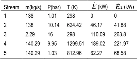
Using the mass flow rate, temperature and pressure obtained from the speedtronics in the control room of the plant and applying the energy balance equations for each component in the plant. The plant is modelled using Matlab software and the result validated by comparing the modelled results with plant data. Table 3, presents the mass flow rates, pressure, and the enthalpy that correspond to the respective state in Figure 1, for the data collected.
Table 3. Property state and exergy streams of SGT Power plant
Stream m(kg/s) P(bar) T (K)
E
(kW)E
x
(kW)1 138 1.01 298 0 0
2 138 10.14 624.42 46.17 41.88
3 2.29 16 298 110.09 263.8
4 140.29 9.95 1299.51 189.02 221.97
5 140.29 1.03 812.96 62.27 68.58
Applying the models in section 3, the result showed that the compressor WAC, turbine work Wturb, net power
output Wnet and the thermal efficiency are 47.2 MW, 75.8
MW, 28.9 MW and 25.7 % respectively. Similarly low thermal efficiencies were reported in the work of Sa and Al Zubaidy [7] and Balli et al., [30]. This is as a result of high ambient temperature and exhaust temperature as reported by Al Ibrahim and Varnham, [31], Poullikk as [20], Wang and Chiou [6], among others. In enhancing the performance of the existing plant the three options of improvement were discussed.
The conditions of SGT various integrations are stated as in Table 2, with each state corresponding to Figure 1. The conditions of the steam generated from the HRSG are 2 MPa and 653.15K, the temperature of the condensate water at inlet to HRSG is 300.15K, pressure drop in HRSG on t e gas side Δ HRSG is 5%. The temperature of the
Table 4 present the thermodynamic properties of SGT and the three proposed Models. From the table the thermal efficiency, net power output and electrical work done of SGT are 25.7%, 28.3 MW and 24 MW respectively. Comparison of the performance of the various models showed that the thermal efficiency of Models 1, 2 and 3 increased by 0.9, 25.3 and 25.5 respectively. The heat rate was observed to have decreased, with Model 3 having the lowest value of 2,299.13 kJ/kWh. The lowest AC work was recorded on the model 1, this is as a result of the reduction in compressor inlet temperature consequently increasing the turbine work of the SGT. the highest net power output was observed in Model 3. This is as a result of wasted energy recovered from the HRSG and the natural gas pressure drop station used to reduce the compressor inlet temperature. This is in agreement with the work of Agarwal, et al., [21], Wang and Chiou [5] and Poullikkas [20].
Furthermore, the lowest specific fuel consumption was recorded on Model 2 and 3 to be 0.15 kg/kWh. It is evident fromTable 4 that Model 3 is able to achieve a capacity boost in thermal efficiency and net power output. This work is in agreement with earlier works of Wang and Chiou [5] and Ziolkowski, et al., [18].
Table 4 Thermodynamic Properties of the Models
Performance parameters GT Model 1 Model 2 Model 3
ηth (%) 25.7 26.61 50.99 51.17
ms (kg/s) 20.59 19.93
HR (kJ/kWh) 4577.91 4420.95 2307.3 2299.13
Specific network (kJ/kg of fuel)
12360. 8
12799. 7
24525. 1
24612. 3
SFC(kg/kWh) 0.29 0.28 0.15 0.15
GT Work(MW) 75.85 74.56 75.85 74.56
AC work (MW) 47.56 45.75 47.56 45.75
Net power output(MW) 28.3 29.3 78.1 78.4
Electrical work done (MW) 24 24.9 66.4 66.7
Figure 8 presents the exergetic efficiency of SGT and other models. It is evident that Model 3 had the highest exergetic efficiency of 47.35%.
Figure 8: Exergetic efficiency of models
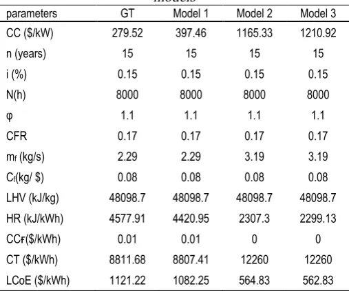
The various models were further compared from the economic point of view keeping in view that the levelized cost of electricity (LCoE) will be used as the major parameter. Table 5 presents the economic analysis of the various models and SGT. the economic life of the plant is taken as 15 years. The results of the economic analysis show that the LCoE of the SGT, Model 1, Model 2, and Model 3 are $1121.22/kWh, $979.75/kWh, $564.83/kWh, and $562.83/kWh respectively. From this result it is evident that Model 3 is the most economical power plant.
Table 5: Economic comparison of SGT and proposed models
parameters GT Model 1 Model 2 Model 3
CC ($/kW) 279.52 397.46 1165.33 1210.92
n (years) 15 15 15 15
i (%) 0.15 0.15 0.15 0.15
N(h) 8000 8000 8000 8000
φ 1.1 1.1 1.1 1.1
CFR 0.17 0.17 0.17 0.17
mf (kg/s) 2.29 2.29 3.19 3.19
Cf(kg/ $) 0.08 0.08 0.08 0.08
LHV (kJ/kg) 48098.7 48098.7 48098.7 48098.7
HR (kJ/kWh) 4577.91 4420.95 2307.3 2299.13
CCғ($/kWh) 0.01 0.01 0 0
CT ($/kWh) 8811.68 8807.41 12260 12260
LCoE ($/kWh) 1121.22 1082.25 564.83 562.83
4. CONCLUSIONS
This paper presents a comparison between three models (i) integration of air inlet cooling (AIC) (Model 1) (ii) Integrating steam in combustion chamber (STIG) (Model 2) and (iii) combination of AIC and integration of steam in combustion chamber (STIG) (Model 3) of improving performance of a simple gas turbine. The results show that Model 3 had the highest thermal efficiency with 51.2% while the net power generation and exergetic efficiency increased by 100%. Although, the fuel consumption mass flow rate increased from 2.29 to 3.19 kg/s, the specific fuel consumption of Model 3 is the lowest. Furthermore, from economic and environmental point of view, the lowest levelized cost of electricity as well as the specific emissions was observed in Model 3. Consequently, Model 3 is selected as the best option in improving the investigated simple gas turbine.
5. REFERENCES
Information Administrationwww.eia.gov/ieo/ July 2013, Accessed Jan 15, 2016
[2] Kaushik, S. C., Reddy V. S and Tyagi S. K. “Energy and e ergy analyses o t ermal power plants: A review”
Renewable and Sustainable Energy Reviews, Vol.15, pp:1857–1872. , 2011.
[3] Najjar Y. S. H. “E icient use o energy by utilizing gas turbine combined systems” Applied Thermal Engineering, Vol. 21: pp: 407-4382001,
[4] ilavac i .A. “ ower generation wit gas turbine systems and combined eat and power” Applied Thermal Engineering, Vol. 20, pp:1421-1429, 2000.
[5] Wang, F. J. and Chiou J. . “ er ormance improvement for a simple cycle gas turbine GENSET––a retrofitting e ample” Applied Thermal Engineering, Vol. 22, pp: 1105– 1115, 2002.
[6] Wang, F. J and iou J. . “ ntegration o steam injection and inlet air cooling for a gas turbine generation system”
Energy Conversion and Management, Vol. 45, pp.15–26. , 2004.
[7] a D. and Al Zubaidy . “Gas turbine per ormance at varying ambient temperature” Applied Thermal Engineering, Vol. 31 pp. 2735-2739
[8] Farzaneh-Gord, M. Deymi-Das tebayaz M. “A new approach for enhancing performance of a gas turbine (case study: K angiran re inery ” Applied Energy, Vol. 86pp.2750–2759, 2009.
[9] Ameri, M. Hejazi, S. H. “ e study o capacity en ancement of the Chabahar gas turbine installation using an absorption c iller” Applied Thermal Engineering, Vol. 24 Number 1, 2004, pp. 59-68.
[10] Ehyaei, M. A Mozafari, A. Alibiglo , M. H. “E ergy economic & environmental (3E) analysis of inlet fogging for gas turbine power plant” Energy Vol. 36, pp. 6851- 6861. , 2011.
[11] Boonnasa Namprakai Muangnapo . “ er ormance improvement of the combined cycle power plant by intake air cooling using an absorption c iller” Energy Vol. 31, pp: 2036-2046, 2006.
[12] Yang Yang Z ai R. “Analytical met od or evaluation o gas turbine inlet air cooling in combined cycle power plant” Applied Energy, Vol. 86 Number 6, pp:848–856. , 2009.
[13] Zurigat, Y. H. Dawoud B. Bortmany J. “On t e tec nical feasibility of gas turbine inlet air cooling utilizing thermal energy storage” International Journal of Energy Research
Vol. 30, 2006, pp: 291-305.
[14] Farzaneh-Gord, M. Deymi-Das tebayaz M. “E ect o various inlet air cooling methods on gas turbine per ormance” Energy Vol. 36, pp: 1196-1205 , 2011. [15] Ghazikhani, M., Manshoori N. Tafazoli D. “E perimental
Investigation of Steam Injection in Ge-F5 Gas Turbine Nox Reduction Applying Vodoley ystem” Second International Conference on Applied Thermodynamics, Istanbul, Turkey, May 18-20, 2005.
[16] Bouam A. Aïssani .and Kadi R. “Gas urbine Performances Improvement Using Steam Injection in the ombustion amber” Oil & Gas Science and Technology– Rev. IFP, Vol. 63, Number 2, pp: 251-261, 2008.
[17] Traverso, A. Massardo A. F. “ ermoeconomic analysis o mixed gas-steam cycles” Applied thermal Engineering Vol. 22, pp: 1-21, 2002.
[18] Ziółkowski . Lemański M. Badur J. and Nastałek L. “ ower Augmentation o GE Gorzow’s Gas urbine by Steam Injection – ermodynamic Overview” Rynek Energii. Vol.1, Number 98, pp: 161-167. , 2012.
[19] Poullikkas A. “An overview o current and uture sustainable gas turbine tec nologies” Renewable and Sustainable Energy Reviews, Vol. 9, pp:409-443. , 2005. [20] Agarwal, S. Kachhwaha S. . and Mis ra R. . “ er ormance
improvement of a simple gas turbine cycle through integration of inlet air evaporative cooling and steam injection” Journal of scientific and industrial research Vol. 70, 2011, pp: 544-533.
[21] Nis ida K. akagi . Kinos ita . “Regenerative steam injection gas-turbine systems” Applied Energy, Vol.81, pp: 231-246. , 2005.
[22] Zadpoor, A. A. Golshan A. H. “ er ormance improvement o a gas turbine cycle by using a desiccant-based evaporative cooling system” Energy Vol. 31, 2006, pp: 2652–2664 [23] Ibrahim T. K., Rahman M. M. and Abdalla A. N. “Optimum
Gas Turbine Configuration for Improving the performance o ombined ycle ower lant” Procedia Engineering
Vol.15pp: 4216 – 4223, 2011.
[24] Maddaloni J. D Rowe A M. “Natural gas e ergy recovery powering distributed ydrogen production” International Journal of Hydrogen Energy, Vol. 32 Number 7 pp: 557– 566. 2007.
[25] Anozie, A. N Odejobi O. J. “ e searc or optimum condenser cooling water flow rate in a thermal power plant” Applied Thermal Engineering Vol.31, pp: 4083-4090, 2011.
[26] Srinivas . Gupta A.V. . .K. .and Reddy B.V “ ensitivity analysis of STIG based combined cycle with dual pressure HR G” International Journal of Thermal Sciences. Vol. 47, pp: 1226–1234, 2008.
[27] Neville, A. M. Properties of Concrete, Pitman, Paperback, London (for Books). , 1970.
[28] Bejan, A. Advanced Engineering Thermodynamics. 3rd edition, John Wiley & Sons, New York. 1998.
[29] Sinnott, R. K. Chemical Engineering Design, Fourth ed., 6, Elsevier Butterworth Heinemann, Oxford. 2005.
[30] Balli, O. Aras H. and Hepbasli A. “E ergoeconomic analysis o a combined eat and power H system”
International Journal of Energy Research, Vol. 32 pp: 273– 289, 2008.