Low Power Test Data Compression Based on LFSR Reseeding
SK.KHAMURUDDEEN*, DR. MAYANK TRIPATHI**
*(Pursuing Ph.D in VBS Purvanchal University, Jaunpur, INDIA)
** (Professor & HOD, Department of ECE, VBS Purvanchal University, Jaunpur, INDIA)
I. Introduction
Built-in self-test (BIST) is widely known as a good solution for testing the individual (Intellectual Property (IP) cores in the large system-on-a-chip (SOC) designs. As a test pattern generator of BIST, a linear feedback shift register (LFSR) is widely adopted to generate a Pseudo - random test pattern. However, in cases that Produce many random pattern resistant (RPR) faults in the circuit under test (CUT), it causes excessive power dissipation. In the LFSR reseeding scheme, don't care bits in the test cubes are filled with pseudo-random bits generated by the LFSR and unnecessary switching activity is produced. In this paper, a new test-data-compression scheme based on linear feedback shift register (LFSR) reseeding that significantly reduces power consumption during test is proposed. Test-data volume has also increased dramatically as the size and the complexity of chips grow. Consequently, there has been a lot of work on test-data-compression schemes that can be used to reduce tester storage and band width requirements. Commercial tools for test- data compression, which are based on LFSR reseeding including Test Compress by Mentor Graphics [1], SOC BIST by Synopsis, and ELT-Comp by Logic Vision have been introduced. The basic idea in LFSR reseeding is to generate deterministic test cubes by expanding seeds. A seed is an initial state of the LFSR that is expanded by running the LFSR. Given a deterministic test cube, a corresponding seed can be computed by solving a set of linear equations (one equation for each specified bit) based on the feedback polynomial of the LFSR. Since typically only 1%-5% of the bits in a test vector are specified, most bits in a test cube do not need to be considered when a Seed is computed because they are don't care bits. Therefore, the size of a seed is much smaller than the size of a test vector. Consequently, reseeding can significantly reduce test-data storage and bandwidth. Several reseeding schemes have been proposed to reduce test storage. The first was introduced in [3], where it was shown that if s max is the largest number of specified bits in any test cube, then for an LFSR While reseeding is a very powerful method for test-data compression, it is not good for power consumption. The don't care bits in each test cube get filled with random values, thereby resulting in excessive switching activity when they are shifted into a scan chain. During normal operation, typically, only a small percentage of flip-flops make transitions during each clock cycle. However, when scanning test vectors whose 95%-99% of the bits have been filled with random values, a very large percentage of the flip-flops will make transitions, thereby resulting in excessive power consumption during test. The chip may be designed to only handle the power consumption during normal operation, and thus the excessive power consumption during test can result in overheating. One solution to this problem is to simply reduce the scan frequency; however, this results in longer test times. Many techniques for reducing power consumption during scan testing have been presented and are summarized in [8]. It was only recently that work has been done on considering together the problems of test-data compression and low-power test. Research in this direction has been presented in [9]-[12] and is summarized in Section I. In this paper, we present a new encoding algorithm that can be used in conjunction with any LFSR reseeding scheme to significantly reduce power consumption during test (preliminary results were presented in [13]). A key feature of the proposed approach is that it reduces the number of specified bits and the number of transitions at the same time. Since the amount of compression for LFSR reseeding depends on the number of specific bits, the proposed
Abstract:
As the size and complexity of systems-on-chips continues to grow, the power dissipation during testing becomes very significant problem. During scan shifting, more transitions occur in the flip-flops compared to what occurs during normal functional operation. This problem is further pseudorandom filling of the unassigned input values is employed. Excessive power dissipation during test can increase manufacturing costs by requiring the use of a more expensive chip packaging or causing unnecessary yield loss. The proposed encoding scheme can be used in conjunction with any lfsr-reseeding scheme to significantly reduce test power and even further reduce test storage is presented. Experimental results show that the proposed scheme can significantly reduce the power dissipation.approach exploits this property. In section II we review the related work. In Section III, we introduce the new encoding scheme. Section IV explains a hardware implementation for the proposed scheme. Section V shows the experimental results, and Section VI concludes this paper.
II. Test Cube Encoding Algorithm
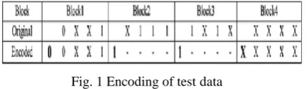
Let a transition in a test cube be defined as a specified 0 (1), followed by 0 or more Xs and then by a specified 1 (0). The key idea of the proposed encoding algorithm is to take advantage of the fact that the number of transitions in a test cube is always less than the number of specified bits in a test cube. Thus, rather than using LFSR reseeding to directly encode the specified bits as in conventional LFSR reseeding, the proposed encoding algorithm divides the test cube into blocks and only uses LFSR reseeding to produce the blocks that contain transitions. For the blocks that do not contain transitions, the logic value fed into the scan chain is simply held constant. This approach reduces the number of transitions in the scan chains and in most cases also reduces
Fig. 1 Encoding of test data
the total number of specified bits that must be generated by the LFSR as compared with conventional LFSR reseeding.
A. Basic Concept
The proposed encoding scheme encodes each test cube with two kinds of data: "hold flags" and "data bits." Each test cube is divided into several blocks, and each block has a 1-bit hold flag. The hold flag indicates whether a transition occurs in a block. There are three types of blocks.
1) Transition block (hold flag = 0). One or more transitions exist in the block. Either both 0 and 1 are present in the block (e.g., XX1X0X) or only 0 or 1 is present, but the last specified bit from a previous block was the opposite value.
2) No transition block (hold flag = 1). No transition occurs in the current block. Only 0 or 1 is Present in the block, and the last specified bit from a previous Block is same (e.g., X0XX0X).
3) Don't care block (hold flag = X). No specified bits occur in the block; all are don't cares. If the hold flag for a block is 1, then the data bits in the block are simply held constant from the last data bit in the previous block. If the hold flag is 0, then the data bits are loaded directly from the LFSR. If the hold flag is X, then it can be treated either as a non transition block or as a transition block with all X data. Both the hold flags and the data bits are generated from a single LFSR using reseeding. An example of the proposed encoding is shown in Fig. 1. The test sequence in the example is composed of four blocks, and each block has one hold flag and four data bits. The hold flags are shown in bold along the "Encoded" bit sequence row. In Fig. 1, the original test cube contains seven specified bits. However, using the proposed encoding scheme, the encoded data only has three specified hold flags and two specified data bits, giving a total of only five specified bits. Thus, the proposed encoding scheme reduces the number of specified bits that need to be generated using LFSR reseeding. As shown in Fig. 1, the 1s in blocks 2 and 3 do not need to be generated directly by the LFSR but are rather generated as a by-product of the fact that the hold flags keep the input to the scan chain constant at 1. Thus, test data compression can be achieved in this way. Moreover, no transitions will occur when generating blocks 2 and 3 because the hold flags are 1, thus keeping all the bits in the blocks constant. This would not be the case in conventional LFSR reseeding, where the Xs in blocks 1 and 2 get filled with random data, which may result in many more transitions. Thus, a reduction in the number of transitions can be achieved in this way.
B. Conversion procedure
don't care as a 0 and thereby convert block 2 into a non transition block. Even though this conversion required adding an extra specified data bit, the net result is still a reduction in the total number of specified bits because now block 2 is a non transition block; thus, none of its data bits need to be generated by the LFSR. This same conversion procedure can also be used to convert block 4 in Fig. 2 into a non transition block. By increasing the number of non transition blocks, the conversion procedure can help to reduce both test storage (since it can reduce the total number of specified bits) and test power (since it can reduce the number of transitions by enabling all the Xs in the converted non transition block to be filled with the same logic value).
Fig. 2 Example of conversion procedure
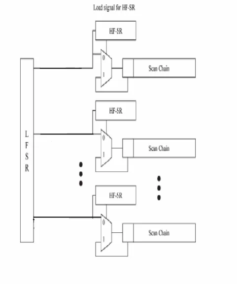
(the last bit of blocks 1 and 3 are specified to convert blocks 2 and 4 into non transition blocks). There is a small finite-state machine (FSM) controller that controls where the data coming out from the LFSR is stored. In the first clock cycle, the LFSR generates a single bit, which is the update flag. If the update flag is 1, then in the next B clock cycles, the LFSR generates the hold flags for each of the
Fig. 3. Hardware architecture of the proposed scheme
Fig-4 FLOW CHART OF CONVERSION PROCEDUR
III. Results for the proposed Encoding scheme
After the scan chains have been filled, the scan vector is applied to the circuit under test, and the response is loaded back into the scan chain. The process is then repeated to generate the next scan vector. The hardware overhead consists of one 2-to-1 MUX and an HF-SR per scan chain, one 1-bit update flag flip-flop, and a small FSM controller. The FSM controller consists of a bit counter (which is present for LFSR reseeding anyway) and some small combinational logic. The size of the HF-SR dominantly determines the hardware overhead in this scheme. It depends on the number of scan chains and the total number of blocks.
Fig-6: Power Report of Conversion Procedure of the TR Scheme
Fig-7 Power Report of Hold cube Minimization Process.
IV. Experimental Results
circuit size. The 11th column indicates the number of 2-to-1 MUXs required, which is equal to the number of scan chains because one MUX is located on the entrance of each scan chain. The size of the HF-SR is indicated in the last column and depends on the number of blocks. Table-2 shows the percentage change in specified bits and power reduction compared to the original test cubes for one benchmark circuit. It illustrates how to choose the number of blocks for a corresponding circuit and test set. The number of blocks is a user- defined variable. With a small number of blocks, the number of specified bits is reduced to less than the number of specified bits in the original test cubes. This is also observed in most of the other circuits. A small number of blocks are also good with respect to hardware overhead because it means small hardware overhead. However, the amount of power reduction is almost proportional to the number of blocks, as shown in Fig., which means that the power consumption with a small number of blocks is small. With five to ten blocks, the power reduction is about 37%, while the average of the power reduction is about 50%. If 37% power reduction is good enough for a user's test methodology, a number from five to ten is chosen as the number of blocks because it causes very small hardware overhead and can achieve high test-data compression. If 37% power reduction is not good enough, the number of blocks is chosen to be larger while still trying to minimize the number of specified bits. In Fig. 6, 38 or 39 blocks can be chosen. This can achieve 48% power reduction and 1.8% reduction of the number of specified bits with relatively small hardware overhead but not as small as hardware overhead with five to ten blocks. The proposed encoding scheme can be used in conjunction with any LFSR reseeding scheme. Experiments were performed for using the proposed encoding scheme in conjunction with the partial LFSR reseeding scheme described in [7]. The results are shown in Table II The exact same set of test cubes that were used for generating the results published in [7] was encoded using The proposed encoding scheme in conjunction with the scheme in [7]. As can be seen, in most cases, both the test storage and the test power are reduced using the proposed scheme.
Table I shows a comparison of the experimental results in [11] and [12] with those of the proposed encoding scheme (used in conjunction with partial LFSR reseeding as described in [7]). As can be seen, the proposed scheme reduces the test-storage requirements much more than the other schemes. Note that the test storage for the method in [12] was calculated here by multiplying the size of the primary and secondary LFSRs by the number of test cubes. In terms of reducing test power, the proposed scheme is much more effective than the scheme in [12], which is also applicable for LFSR reseeding. Moreover, the compression ratio in the proposed scheme is similar or even higher than that in [12] even though 1000 pseudorandom patterns are applied first in [12]. Note that the results for both [11] and the proposed scheme are for encoding the entire deterministic test set. While the test power for the proposed scheme is not reduced as much as for the scheme in [11], which is based on run-length encoding, much more compression is achieved. The key advantage of the proposed scheme compared with [11] is that it is compatible with LFSR reseeding, which is used in commercial tools due to its superior encoding efficiency.
S.No Name of the
Scheme
Power
Consumption(mW)
1. Basic Concept 32
2. With TR
Algorithm
22
3. Hold Cube
Minimization
18
Table-1 Comparison between with and without TR algorithm
S.No Name of the Scheme %Power Reduction
1. With TR Algorithm 35%
2. Hold Cube Minimization 42%
Fig. 8: Simulation results of Hold cube Minimization Process
V. CONCLUSION
LFSR reseeding is a good solution for testing large SOC, but causes excessive power dissipation. This paper has proposed a new low power scheme using the LFSR reseeding. The proposed scheme divides each test cube into several transitional or transitional blocks, and can eliminate the transitions introduced in the non-transitional blocks. The original test cube is encoded into the low power test cube. The proposed encoding scheme provides a way to reduce the test power for lfsr. And also improving the test compression is achieved.
References
[1]. . Rajski, J. Tyszer, M. Kassab, N. Mukherjee, R. Thompson, T. Kun-Han, A. Hertwig, N. Tamarapalli, G.
Mrugalski, G. Eider, andG. Jun, "Embeddeddeterministic test for low cost manufacturing test," in Proc. Int. Test Conf., 2002, pp. 301-310.
[2]. B. Koenemann, C. Barnhart, B. Keller, T. Snethen, O. Farnsworth, and D. Wheater, "A SmartBIST variant with guaranteed encoding," in Proc.VLSI Test Symp., 2001, pp. 325-330.
[3]. B. Koenemann, "LFSR-coded test patterns for scan designs," in Proc. Eur.test Conf., 1991, pp. 237-242. [4]. S. Hellebrand, S. Tarnick, J. Rajski and B. Courtois, “Generation of vector patterns through reseeding of
multiple-polynomial linear feedback shift register," in Proc. Int. Test Conf., 1992, pp. 120-129.
[5]. S. Hellebrand, J. Rajski, S. Tarnick, S. Venkataraman, and B. Courtois, "Built-in test for circuits with scan based on reseeding of multiplepolynomial linear feedback shift registers," IEEE Trans. Comput. vol. 44, no. 2, pp. 223-233, Feb. 1995
[6]. N.Zacharia, J. Rasjski and J. Tyszer, "Decompression of test data using variable-length seed LFSRs," in Proc.VLSI Test Symp., 1995, pp. 426-433.
[7]. C. V. Krishna, A. Jas, and N. A. Tuba, "Test vector encoding using partial LFSR reseeding," in Proc. Int. Test Conf., 2001, pp. 885-893.
[8]. P.Girard, "Survey of low-power testing of VLSI circuits," IEEE Des. Test Comput. vol. 19, no. 3, pp. 82-92, May/Jun. 2002.
[9]. R. Sankaralingam, R. R. Oruganti, and N. A.Touba, "Static compaction techniques to control scan vector power dissipation," in Proc. VLSI Test Symp., 2000, pp. 35-40.
[10]. A. Chandra and K. Chakrabarty, "Combining low-power scan testing and test data compression for system-on-a-chip," in Proc. Des. Autom. Conf., 2001, pp. 166-169.
[11]. “Reduction of SOC test data volume, scan power and testing time using alternating run-length codes,” in Proc. Des. Autom. Conf., 2002, p. 673-678.
[12]. P. M. Rosinger, B. M.AlHashimi, and N. Nicolici, "Low power mixedmode BIST based on mask pattern
generation using dual LFSRreseeding," in Proc. Int. Conf. Comput. Des. 2002, pp. 474-479.
[13]. J. Lee and N. A. Tuba, "Low power test data compression based on LFSR reseeding," in Proc Int. Conf. Comput. Des., 2004, pp. 180-185.