Constant False Alarm Rate for Target Detection by Using
First Order and Second Order Microwave Differentiators
Srinivasa Rao Sankranti1,*, Tirumala Krishna Battula2, Malleswara Rao Veera1
1Dept. of ECE, GITAM University, Rushikonda, Visakhapatnam, Andhra Pradesh, India 2Dept. of ECE, UCEV, JNT University Kakinada, Vizianagaram, Andhra Pradesh, India
Abstract
The main objective of this paper is to detect a target in marine RADAR by persevering constant false alarm rate using first order and second order microwave differentiators. In existing detection, conventional differentiators, which are made with R & C components were used. By using this RC differentiator, the display system of the target detecting RADAR was overwhelmed as they are having less gain. So the target may be undetected even though its strength is high. By using these microwave differentiators, the display system of the RADAR can be increased. The simulations are carried out using ADS environment.Keywords
Fast Time Constant (FTC), Microwave Differentiator, Constant False Alarm Rate (CFAR), Clutter, Micro strip, ADS (Advanced Design Software) etc
1. Introduction
In order to find the time derivative of the incoming signal Digital Differentiators [1-3] are used. The considerable drawback of these digital diffrentiator is that they can work efficiently upto 500MHz. D.C. Chang and C.W. Hsue [4] explains the design and implementation of digital filters at microwave frequencies by using transfer functions in the Z domain. Chin-Wen Hsue, Lin-Chuan Tsai and Kuo-Lung Chen, [5, 6] describe the implementation of first order and second order Microwave Differentiators by using bilinear transformation method. S.S.Rao et.al [7] proposed a method of designing a first order differentiator at microwave frequencies by converting the transfer function which is in z-domain to S-domain [8] by using the transformation techniques. G. V. Weinberg [9] explains how Pareto distribution can be used as a model for all grazing angle scenarios. K. J. Sangston et.al [10] explains detecting a radar target signal against correlated non-Gaussian clutter, which is modeled by the compound-Gaussian distribution.
The microwave differentiators are used [11] in target detection of marine RADAR applications. The tracking computers are used to detect the radar signal and extract the target information enclosed in that signal. The tracking computers cannot detect it, if the radar signal is displayed along with the clutter. Generally, this happens, if the tracking computers are overloaded.
* Corresponding author:
[email protected] (Srinivasa Rao Sankranti) Published online at http://journal.sapub.org/ijea
Copyright © 2016 Scientific & Academic Publishing. All Rights Reserved
The paper is organized as follows:Section 2 deals about Log FTC receiver and design of FTC circuit by using R&C components. Section 3 deals with FTC circuit implementation using first & second order Microwave differentiator and comparsion of the same. Results and conclusions are discussed in Section 4.
2. Design of FTC Circuit by Using R &C
Components
Figure 1. FTC Circuit
The log-FTC, or similar CFAR [13], is necessary, however, in order to extract the target information contained in the radar signal that otherwise would be undetected if displayed along with the clutter, or which would be lost because of computer overload in an automatic system. Although one of the first applications considered for the log-FTC receiver was the detection of targets in sea clutter [13]. In general, the time constant is usually about one pulse length. All radars provide a FTC or differentiator on/off control, usually with control of time constant, giving the operator more scope to balance detect ability against display quality. As differentiation diminish echo plots, it should be disengaged in clear conditions.
3. FTC Circuit Implementation by Using
First Order and Second Order
Microwave Differentiator
The traditional differentiator which was formed with RC components is replaced by the first order and second order microwave differentiator which is formed with micro strips is as shown in figure 5 and figure 7.
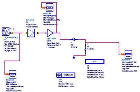
Figure 2. FTC Circuit implementation in ADS Software (by using RC components)
Figure 3. Chirp input signal
200 400 600 800 1000 1200 1400 1600 1800
0 2000
-1E-15 0 1E-15
-2E-15 2E-15
Index
dB
(C
hir
p_s
ignal
_IN
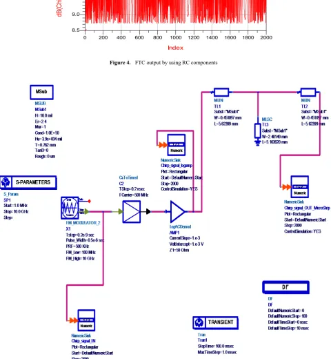
Figure 4. FTC output by using RC components
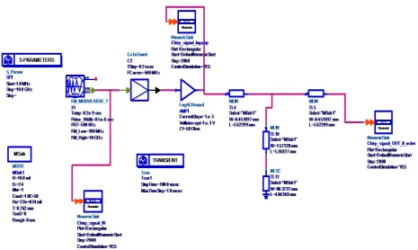
Figure 5. FTC circuit implementation using First Order Microwave differentiator
200 400 600 800 1000 1200 1400 1600 1800
0 2000
9.0 9.5 10.0 10.5 11.0
8.5 11.5
Index
dB
(C
hi
rp_s
ignal
_O
UT
_R
Figure 6. FTC output by using first order microwave differentiator
Figure 7. FTC Circuit using Second order Microwave differentiator
Figure 8. FTC Circuit output using Second order Microwave differentiator
200 400 600 800 1000 1200 1400 1600 1800
0 2000
-175 -170 -165 -160 -155
-180 -150
Index
dB
(C
hi
rp_s
ignal
_O
U
T_M
ic
roS
tri
p)
200 400 600 800 1000 1200 1400 1600 1800
0 2000
-150 -148 -146 -144 -142
-152 -140
Index
dB
(C
hi
rp_s
ignal
_O
U
T_I
I_or
der
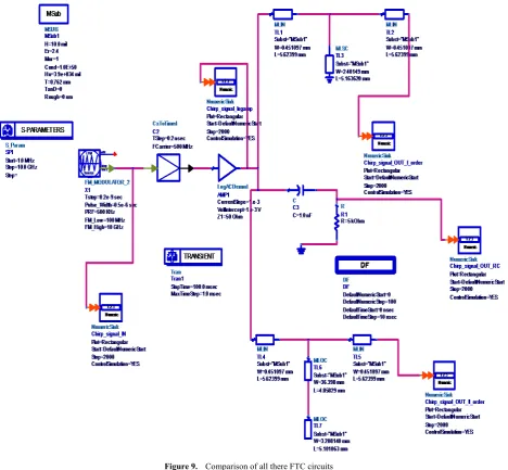
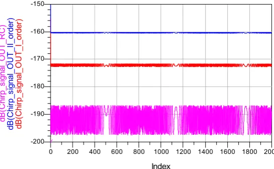
Figure 9. Comparison of all there FTC circuits
Figure 10. Magnitude Comparison of all three FTC circuits
200 400 600 800 1000 1200 1400 1600 1800
0 2000
5.0E-9 1.0E-8 1.5E-8 2.0E-8 2.5E-8 3.0E-8
0.0 3.5E-8
Index
m
ag(
Chi
rp_s
ignal
_O
UT
_I_or
der
)
m
ag(
Chi
rp_s
ignal
_O
UT
_II
_or
der
)
m
ag(
Chi
rp_s
ignal
_O
UT
_R
Figure 11. Variation of gain in dB of all three FTC circuits
Figure 12. Magnitude response Microwave differentiators
4. Results and Conclusions
A differentiator, which is set by using basic components like capacitor (C) and resister (R) as shown in fig 1.The same circuit is performed in Advanced Design Software (ADS) as shown in fig 2 and the input is applied by using chirp signal generator. The output of the circuit is shown in figure 4. By observing the output, the clarity of the signal is not good, i.e the gain is less. So as the gain is less, eliminating the mean value of the clutter is difficult. Even a small increases in background clutter could result in excessive false alarms that overload the capacity of the tracking computer. So there is a probability of missing the target.
RC Differentiator circuit is replaced with first order microwave differentiator which is made of micro strip lines as shown in fig 5. The output for the same circuit is shown in figure 6. By examining the output, the clarity of the signal is good when compared to RC differentiator, i.e the gain is high when compared to RC differentiator. As the gain is increased by 12dB, removing the mean value of clutter is easy when compared to RC Differentiator. So the tracking computer is less overloaded as CFAR works better. So there is less chance of missing the target.
RC Differentiator circuit is replaced with second order microwave differentiator which is made of micro strip lines as shown in fig 7. The output of the same is shown in fig 8. By studying the output, the clarity of the signal is very good when compared to RC differentiator & first order microwave differentiator, i.e the gain is increased by 28dB and 16dB respectively. As the gain is very high, removing the mean value of clutter is very easy when compared to RC Differentiator & first order microwave differentiator. So the tracking computer is very less overloaded as CFAR working in best way. So there is very less probability of missing the target. The comparison of all three differentiators is shown in fig 9 and the same magnitude response output is shown in fig 10 and gain in dB is shown in fig 11. The magnitude response of microwave differentiators which are shown in fig 12 are same as the magnitude response of digital differentiators.
REFERENCES
[1] M.A. Al-Alaoui, Novel Digital integrator and
Differentiator-IEEE Electronic Letters, Vol.29, no.4,
pp.376-378, Feb.1993.
[2] M.A. Al-Alaoui, Novel approach to designing Digital
Differentiators-IEEE Electronic Letters, Vol.28, no.15,
pp.1376-1378, Jul.1992.
[3] B.T. Krishna, S. Srinivasa Rao, On design and applications
of digital differentiators, 978-1-4673-5584-1/12,
IEEE-ICoAC 2012.
[4] D.-C. Chang and C.-W. Hsue, “Design and mplementation of filters using transfer functions in the Z domain,” IEEE Trans.
Microwave Theory Tech., vol. 49, pp. 979–985, May 2001.
[5] Ching-Wen Hsue, Lin-Chuan Tsai and Kuo-Lung Chen, Implementation of First-Order and Second-Order Microwave
Differentiators, IEEE Microwave Theory and Techniques,
vol.52, n0.5, pp.1443-1447, May 2004.
200 400 600 800 1000 1200 1400 1600 1800
[6] C.W. Hsue, Tun-Ruey Cheng and Hwan-Mei Chen, A Second
order Microwave Differentiator, IEEE Microwave and
Wireless Components Lett, vol.13, no.3, pp.137-139, Mar 2003.
[7] S.R Sankranti, T.K. Battula, M.R Veera, Design and implementation of first order digital differentiator at
microwave frequencies, American Journal of Signal
Processing 5(3): 56-58 Dec 2015.
[8] Dean A. Frickey, Conversions between S, Z, Y, H, ABCD, and T parameters which are valid for complex source and load
impedances transform, IEEE transactions on microwave
theory and techniques., vol 42, no 2.
[9] G. V. Weinberg, Assessing the Pareto Fit to High Resolution High Grazing Angle Sea Clutter, IET Electronics Letters, 2011, 47, 516-517.
[10] K. J. Sangston, F. Gini and M. S. Greco, Coherent Radar Target Detection in Heavy-Tailed Compound Gaussian Clutter, IEEE Transactions on Aerospace and Electronic Systems, 48, 2012, 64-77.
[11] John N. Briggs, Target Detection by Marine Radar, The Institution of Electrical Engineers, London, 2004.
[12] Jia−Sheng Hong, M. J. Lancaster, Microstrip Filters for
RF/Microwave Applications, John Wiley & Sons, 2001.
[13] Merrill I. Skolnik, Introduction To Radar Systems, Second
Edition, Mcgraw-Hill Book Company1980.