Analysis of Die Casting Tool Material
Mitja Muhič1,* - Janez Tušek 2 - Franc Kosel 2 - Damjan Klobčar 2 1 TKC Technology Consulting Center, Slovenia
2 University of Ljubljana, Faculty of Mechanical Engineering, Slovenia
This paper deals with defects produced in aluminium alloy die casting dies during die operation. The most frequent defect is thermal fatigue cracking. Hardness and toughness is measured on specimens cut from different parts of used die casting die.
The results show a significant difference in material microstructure and hardness between the surface and the core. The intense martensite tempering is observed on the die surface, while the core material microstructure remains unchanged. A considerable hardness drop is measured on the material surface and no change is observed in the depth of six millimetres from surface.
© 2010 Journal of Mechanical Engineering. All rights reserved. Keywords: die casting, die defect, thermal fatigue, surface cracks
0 INTRODUCTION
Die casting is an effective production process for manufacturing complex shaped cast products. Die casting dies for aluminium and copper alloy die casting are exposed to severe thermal, mechanical and chemical loads [1] to [3]. Capacity and in-service die casting die life are limited for various reasons, e.g.: thermal fatigue cracking, erosion, corrosion, soldering, deformation and gross fracture [1] to [7].
Die casting dies are usually made of hot work tool steel in order to minimize die defects. Thermal fatigue cracking is the dominant failure of die casting dies [5] to [14]. Crack networks appear on surfaces, which are exposed to thermal cycles. These crack networks grow and propagate with the continuous use of the dies, hence degrading the quality of die surfaces and consequently the quality of cast surfaces.
1THERMALFATIGUEOFDIECASTING DIES
Surface cracks occur on the surface of the dies due to mechanical and thermal loads and erosion. Die surface is exposed to high temperatures and pressure due to the contact with the hot melt, which changes material structure and microstructure and degrades material mechanical properties: hardness and strength [5] to [13]. Heating and cooling cycles cause thermal extension and contraction of material, thereby generating stress and strain fields. Local
accumulation of plastic deformation leads to local failures - cracks originate and propagate with further use of the dies [8] to [10]. Local material failures first appear at critical die locations. This is where shape and geometry change abruptly (corners with small radiuses) and residual stresses due to the tool production are present. Melt pressure shocks also appear at these critical locations, thereby additionally decreasing the in-service die life. At these locations melt velocity and kinetic energy decrease resulting in an increase in melt pressure and pressure energy (Bernoulli's principle) [15] which additionally increases loads on the die surface.
2 EXPERIMENTAL INVESTIGATION OF DIE CASTING DIE
21. This repeated repair welding prolonged the in-service die life by factor 3.
Fig. 1. The moving part of the die. White arrows show locations of repair welding
The die was made of chromium-molybdenum-vanadium alloy hot work tool steel. The surface hardness of the analized tool was 450 HV ~ 46 HRC. Impact toughness of the material was determined with charpy impact test (V-notch ASTM A370). Values of toughness varied from 10 to 12 J. Mechanical and physical properties of the die material are presented in Table 1.
The casting melt was an aluminium alloy AlMg2 (Table 2) with the entrance temperature of 740 ± 10 °C and specific melt pressure 1090 ± 40 bar. The melt velocity at the entrance was 31 m/s. Filling time of the die with melt was 30 ± 0.20 ms and the melt solidification time was 8 s.
The die was cooled with a mixture of water and oil, which was circulating in cooling channels in two loops inside the die. The external loop of the die was heated at 250 °C and internal loop at 180 °C. Before each die casting cycle the die surface was sprayed with water-soluble lubricant, to prevent the melt sticking to the die surface.
Table 1. Mechanical and physical properties of the Cr-Mo-V alloy hot work tool steel AISI H11, UNE X37 CrMoV 5, EN DIN W. No.: 1.2343
Temperature [°C]
Property 20 600
Tensile strength [MPa] 1400 700 Yield strength [MPa] 1200 500 Modulus of elasticity [GPa] 215 165 Reduction of area [%] 50 75
Density [kg/m3] 7800 7600
Specific heat [J/kgK] 460 590
Thermal expansion between
20°C [10-6 m/mK] 11 13
Thermal conductivity
[W/mK] 25 29.1
3 THE ANALYSIS OF DIE MATERIAL AND CRACKS
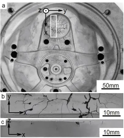
Fig. 2 shows the surface close-up of the discussed die casting die. The biggest cracks and the highest density of surface cracks were at the die gate, where melt with high temperature entered into the die. The crack density, length and depth quickly decreased with the increased distance from the die gate. Surface was strongly damaged at a distance of less than 100 mm from the die gate, while the cracking was negligible at a distance over 200 mm from the die gate.
This observation shows that the temperature to which the die surface is heated, is the most influential factor in the cracks formation process [5] to [14]. High temperature at the die gate is required to adequately fill the entire form. An important role can also be attributed to high melt pressure and melt velocity, which additionally degrade the die surface. In addition, the presence of stress concentrations (consequence of complex shape and geometry as well as the manufacturing process of the die, repair welding etc.) negatively affects the in-service die life.
Table 2.Chemical composition (mas. %) of the Cr-Mo-V alloy hot work tool steel (AISI H11) and the aluminum alloy ISO AlMg2 used in the experiment
Alloy C Cr Mo V Si Cu Mn Chemical composition [%] Mg Fe Zn Ti Al
H11 0.38 5.00 1.30 0.40 1.10 / 0.40 / Rest / / /
First the die was cut with electrical discharge machining (EDM) into smaller blocks from which specimens were prepared. The specimens were then grinded, polished and etched in 4% nital solution. The specimens were investigated using optical microscope and scanning electron microscope (SEM). The shape, size and density of cracks and microstructure were analysed.
Figs. 2a, b and c show a specimen cut out from the die surface. Cracks on the surface and in the cross section are clearly visible. They vary in size, shape and density depending on their location on the die surface. Fig. 3 enabling us to determine depth of cracks.
Cracks varied in depth. They were deeper on locations closer to the die gate where temperatures and melt pressure were higher during the casting process. Extremely deep cracks were observed on locations with high stress concentrations (i.e. edges and corners with small radiuses). Some cracks became wider on the surface due to the erosion of melt. Another reason for crack widening could be combining two or more cracks into one. This eliminates the surface material between the cracks and causes it to widen. Furthermore, crack widening in depth is also possible due to corrosion (oxidation) [5] and [10]. Critical depths of cracks measured on casts are between 0.01 and 0.1 mm on surfaces contacting the cast and 1 mm on the surface at the die gate. The repair welding was performed when crack depth exceeded these critical values .
Changes in material microstructure were observed up to 5 mm under the surface (Fig. 4). Hard martensite structure becomes softer (tempered martensite) near the surface due to high temperature cycles, which decreased hardness and tensile strength. The level of thermal fatigue decreased with the distance from the surface [5] and [6]. Due to lower material strength and because of thermal fatigue on the die surface, thermo-mechanical loads (stresses) exceeded elastic strength which produced plastic deformation. This lead to local material failure and crack nucleation [8] to [10].
Fig. 5 shows typical thermal cracks as observed with scanning electron microscope (SEM) at different magnifications. The microstructure of materials around and inside the cracks can be seen. Some wider cracks are filled with the melt and have oxidized surfaces.
Fig. 2.a) White rectangle shows where the specimen was cut out from the die, b) a detailed
view of the surface, c) a cross section of the specimen
Fig. 3. A detailed view of the cracks in the cross section
Fig. 4. The microstructure of the material: a) on the surface HV=370 and b) 3 mm below the
surface HV=420
Fig. 5. Typical thermal cracks at different magnifications with SEM
Fig. 6. Elements concentrations in the crack and crack surroundings
concentrations of Al and Mg from the molten aluminium alloy and O from oxides are observed. On the crack borders higher concentrations of Cr and Mo and lower concentrations of Fe are observed. Similar observations were also reported in the next publications [10] and [13].
4 HARDNESS AND TOUGHNESS OF DIE MATERIAL
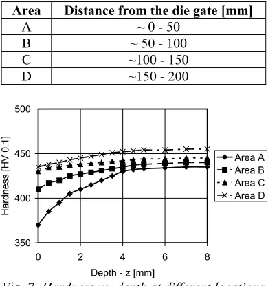
The die material microstructure near the surface is gradually tempering due to contact with molten aluminium alloy, which reached temperatures of up to 740 °C. High molten metal temperature causes tempering of the martensite and consequently the decrease of hardness [8] to [10]. Hardness is the lowest on the surface at the die gate where cracks are deepest and crack density is the highest. Surface hardness increases rapidly with distance from the die gate and Figs. 7 and 8 present the relationship between hardness and distance from the surface for areas at different distances from the die gate. Hardness is the lowest on the die surface and die material is affected (tempered) up to 5 mm below surface.
Area Distance from the die gate [mm]
A ~ 0 - 50
B ~ 50 - 100
C ~100 - 150
D ~150 - 200
350 400 450 500
0 2 4 6 8
Depth - z [mm]
H
ard
ne
ss [H
V
0
.1]
Area A Area B Area C Area D
Fig. 7. Hardness vs. depth at different locations on the die
300 350 400 450 500
0 50 100 150 200
Distance from the die gate [mm]
Su
rf
ace hardn
ess
[HV 0.1
]
Fig. 8. Surface hardness vs. distance from the die gate
Surface area distanced less then 200 mm from the die gate was exposed to the high temperature above 500 °C for about 10 s at each cycle which amounts to 180,000 cycles in around 500 hours. Above 500 °C the hardness of material is significantly lower and decreases even more with higher temperature as can be seen in Fig. 9.
strongly decreased material hardness (Fig. 10) [18].
Fig. 9. Effect of time on hardness at various elevated temperatures [16]
250 300 350 400 450 500 550 600 650
0 100 200 300 400 500 600 700
Temperature [°C]
Surf
ace
hardne
ss
[
H
V
0.
1]
Fig. 10. Chart for hardening temperature 1020 °C and specimen square size 50 mm [16]
Toughness at working temperature is an important die material property. Toughness was measured in the subsurface material, at different distances below the die surface (Fig. 11) using the Charpy impact test and a standard ISO V-notch probe (ASTM A370). The results showed the influence of the distance from the die gate, the distance from the die surface and the distance from the cooling channels on the toughness measured (Table 3). The toughness of the die material before being used in the process of die casting was between 10 and 12 J. Due to the inability to make the probes from the surface material which was in contact with the molten aluminium alloy, the toughness was measured at a relatively long distance from 2 to 34 mm from the
die surface, which is why no significant difference from the measured toughness was observed (Table 3).
Fig. 11. Specimens positions
Table 3. Results of die material specimens toughness
Number of specimen
Distance from die
gate [mm]
Depth from surface
[mm]
Toughness [J]
1 0 8 13.7
2 30 34 9.5
3 80 2 9.1
4 90 22 8.4
5 100 38 9.1
6 110 34 8.9
7 100 32 9.5
8 100 27 9.5
9 110 30 10.3
10 120 15 7.4 11 130 2 9.4
5 CONCLUSION
because of a higher melt temperature and higher melt flow rate. The observed crack depth was from a few tenths of a millimeter up to three millimeters.
The die material microstructure near the surface is gradually tempered due to hot aluminium melt. This causes hardness to decrease; it dropped from 450 to 370 HV on the surface near the die gate. Surface softening promotes crack initiation and propagation. Crack growth is facilitated by filling cracks with melt, and by oxidation.
6 REFERENCES
[1] Sully, L.J.D. (1988). Metals handbook. Vol. 15. Metals Park, OH: ASM International. [2] Davis, J.R. (1995). ASM Speciality
Handbook. Tool Materials. Materials Park, OH: ASM International.
[3] Allsop, D.F., Kennedy, D. (1983). Pressure Diecasting. Part 2: The Technology of the Casting and the Die. Pergamon Press, Oxford.
[4] Young, W. (1979). Why die casting dies fail,
10th SDCE International Die Casting
Exposition and Congress. St. Louis, MO: North American Die Casting Association, p. 1-7.
[5] Kosel, F., Kosec, L. (1983). Heat checking of hot work tool steel. Strojniški vestnik - Journal of Mechanical Engineering, vol. 29, no. 7/8, p. 151-158.
[6] Wallace, J.F., Schwam, D. (2000). Development studies on selection and processing of die materials to extend die life,
Die casting engineering, p. 50-58.
[7] Kosec, B., Kosec, L., Kopač, J. (2001). Analysis of casting die failures. Engineering Failure Analysis, vol. 8, p. 355-359.
[8] Persson, A., Hogmark, S., Bergstrom, J. (2004). Simulation and evaluation of thermal fatigue cracking of hot work tool steels.
International Journal of Fatigue, vol. 26, p. 1095-1107.
[9] Persson, A., Hogmark, S., Bergstrom, J. (2005). Thermal fatigue cracking of surface engineered hot work tool steels. Surface & Coatings Technology, vol. 191, p. 216-227. [10] Persson, A., Bergstrom, J., Hogmark, S.
(2004). Failure modes in field-tested brass die casting dies. Journal of Materials Processing Technology, vol. 148, p. 108-118.
[11] Klobčar, D., Tušek, J., Taljat, B. (2008). Thermal fatigue of materials for die-casting tooling. Materials Science and Engineering: A, vol. 472, no. 1-2, p. 198-207.
[12] Klobčar, D., Tušek, J., Taljat, B., Kosec, L., Muhič, M. (2008). Suitability of maraging steel weld cladding for repair of die casting tooling. International Journal of Materials Research,vol. 99, no. 9, p. 1006-1014. [13] Klobčar, D., Tušek, J., Pleterski, M., Kosec,
L., Muhič, M. (2008). Analysis of thermal cracks on die casting dies. Materials and technology, vol. 42, no. 5, p. 203–210. [14] Jovičić, G., Živković, M., Jovičić, N. (2009).
Numerical Simulation of Crack Modeling using Extended Finite Element Method.
Strojniški vestnik - Journal of Mechanical Engineering, vol. 55, no. 9, p. 549-554. [15] Bernoulli, D.: Hydrodynamica. Britannica
Online Encyclopedia. http://www.britannica. com/EBchecked/topic/658890/Hydrodynami ca#tab=active~checked%2Citems~checked& title=Hydrodynamica%20%20Britannica%2 0Online%20Encyclopedia - last update: 30.10.2008.
[16] Bohler Uddeholm. http://www.bohler-uddeholm.com/, accessed on 2007-06-21. [17] Grange, R.A., Hribal, C.R., Porter, L.F.
(1977). Hardness of Tempered Martensite in Carbon and Low Alloy Steels. Metall. Trans. A, vol 8A.